Báo cáo hóa học: " A Proxy Architecture to Enhance the Performance of WAP 2.0 by Data Compression" ppt
Bạn đang xem bản rút gọn của tài liệu. Xem và tải ngay bản đầy đủ của tài liệu tại đây (697.86 KB, 10 trang )
EURASIP Journal on Applied Signal Processing 2005:1, 57–66
c
2005 Hindawi Publishing Corporation
A Proxy Architec ture to Enhance the Performance
of WAP 2.0 by Data Compression
Zhanping Yin
Department of Electrical and Computer Engineering, The University of British Columbia, Vancouver,
BC, Canada V6T 1Z4
Email:
Victor C. M. Leung
Department of Electrical and Computer Engineering, The University of British Columbia, Vancouver,
BC, Canada V6T 1Z4
Email:
Received 11 June 2004; Revise d 17 November 2004; Recommended for Publication by Weihua Zhuang
This paper presents a novel proxy architecture for wireless application protocol (WAP) 2.0 employing an advanced data compres-
sion scheme. Though optional in WAP 2.0, a proxy can isolate the wireless from the wired domain to prevent error propagations
and to eliminate wireless session delays (WSD) by enabling long-lived connections between the proxy and wireless terminals. The
proposed data compression scheme combines content compression together with robust header compression (ROHC), which
minimizes the air-interface traffic data, thus significantly reduces the wireless access time. By using the content compression at
the transport layer, it also enables TLS tunneling, which overcomes the end-to-end security problem in WAP 1.x. Performance
evaluations show that while WAP 1.x is optimized for narrowband wireless channels, WAP 2.0 utilizing TCP/IP outperforms WAP
1.x over wideband wireless channels even without compression. The proposed data compression scheme reduces the wireless ac-
cess t ime of WAP 2.0 by over 45% in CDMA2000 1XRTT channels, and in low-speed IS-95 channels, substantially reduces access
time to give comparable per formance to WAP 1.x. The performance enhancement is mainly contributed by the reply content
compression, with ROHC offering further enhancements.
Keywords and phrases: w i reless networks, wireless application protocol, wireless proxy.
1. INTRODUCTION
Wireless Internet access is an emerging service that is consid-
ered central to the commercial success of the next-generation
cellular networks. The wireless application protocol ( WAP)
is the convergence of three rapidly evolving network tech-
nologies: wireless data, telephony, and the Internet. It is
the de facto world standard for the presentation and deliv-
ery of wireless information services on mobile phones and
other wireless terminals. WAP is a result of continuous work
to define an industry-wide specification for developing ap-
plications that operate over wireless communication net-
works [1]. The WAP specifications address mobile network
characteristics and operator needs by adapting existing net-
work technology to the special requirements of mass-market,
handheld wireless data devices and by introducing new tech-
nology where appropriate.
This is an open-access article distributed under the Creative Commons
Attribution License, which permits unrestricted use, distribution, and
reproduction in any medium, provided the original work is properly cited.
WAP 1.x is a standard aimed at optimizing the perfor-
mance of wireless Internet access under such limitations as
low bandwidth, high latency, less connection stability, and
bearer availability for wireless networks, and limited screen
display area, input facilities, memory, processing, and bat-
tery power for the mobile handset. The WAP Forum released
version 2.0 of WAP in July 2001. WAP 2.0 brings the wire-
less world closer to the Internet by adopting the most recent
Internet standards and protocols. It also optimizes the us-
age of emerging wireless networks with higher bandwidths
and packet-based connections and maintains compatibility
with WAP 1.x compliant contents, applications, and services.
A major development of WAP 2.0isthatitprovidessupport
for standard Internet protocols such as transmission control
protocol (TCP) and hypertext transfer protocol (HTTP), and
permits applications and services to operate over all existing
and foreseeable air-interface technologies and their bearer
services, including general packet radio service (GPRS) and
third-generation (3G) cellular standards such as WCDMA
and CDMA2000 [2]. In particular, WAP 2.0 utilizes the wire-
less profiled TCP (WP-TCP) [3] and wireless profiled HTTP
58 EURASIP Journal on Wireless Communications and Networking
(WP-HTTP) [4] that are optimized for wireless networks and
interoperable with TCP and HTTP, respectively.
While some performance evaluations of WAP are found
in the literature, they are mainly based on simulations
employing theoretical t raffic models. WAP performance over
GPRS and g lobal system for mobile communications (GSM)
networks has been studied and several traffic models devel-
oped in [5, 6, 7]. WAP end-to-end security issues have been
discussed in [8, 9, 10], and collocating the gateway with the
WAP server in the secured enterprise site seems to be the
only viable solution that strictly guarantees end-to-end se-
curity [8]. All these studies were based on the WAP 1.x pro-
tocol stack. There is little work done in evaluating WAP per-
formance in realistic networks using real WAP traffic. Also,
since WAP 2.0 has been newly released, there has not been
any comparison of the performance of WAP 2.0 stack ag ainst
WAP 1.x stack in the literature.
Compared with wireline, wireless bandwidth is a scarce
resource. However, most data applications and web con-
tents have been developed for wireline networks. To im-
prove bandwidth utilization, data compression schemes can
be used when these applications or data are accessed over
wireless networks. While many standards exist for the com-
pression of audio and video data [11, 12], and for data
transmissions over voice band modems [13], WAP requires
the application of data compression over the wireless net-
work at the wireless transaction layer in a manner that is
transparent to the w ireless data bearer service. In WAP 1.x,
a content encoding approach is used at the WAP gateway
to compress the data. Althoug h WAP 2.0isanevolutional
step forward, by adopting the HTTP/TCP/IP stack, it also
has some disadvantages compared to the WAP 1.x proto-
col stack employing the wireless session protocol (WSP) and
wireless transaction protocol (WTP); for example, the same
message is transmitted using a much larger number of bits,
and the same session requires more transactions. There-
fore, content compression should also be used in WAP 2.0;
but suitable compression methods for WAP 2.0 that pre-
serve end-to-end security have not yet been standardized,
nor has the performance of data compression in WAP 2.0
been evaluated.
In this paper, a novel proxy architecture employing an ad-
vanced data compression scheme is introduced for WAP 2 .0
to minimize the air-interface traffic without protocol conver-
sions. It also overcomes the end-to-end security problem in
WAP 1.x. The performance of the data compression proxy
scheme is compared against the standard WAP 2.0proxycon-
figuration and WAP 1.x protocol stack through experimen-
talmeasurementsoverdifferent emulated wireless networks.
Results show that the proposed data compression scheme sig-
nificantly improves the WAP 2.0 performance in all cases.
Our results enable appropriate configuration of the WAP 2.0
protocol stack for various bearer services.
The rest of the paper is organized as follows. In Section 2,
we review the WAP proxy architecture and the end-to-end
security issue, and describe the proposed data compres-
sion scheme for WAP 2.0. In Section 3, we introduce the
simulation method and the performance evaluation crite-
Content
HTTP
server
Web ser ver
Request (URL)
Content
WAP proxy
Encoder/decoder
and
feature
enhancements
Encoded request (URL)
Encoded content
WAP cleint
WAP micro
browser
Figure 1: WAP proxy model.
Web
server
WAE
HTTP
TLS
TCP
IP
WAP 1.x ga teway
WSP
WTP
WTLS
WDP
Bearer
HTTP
TLS
TCP
IP
WAP
device
WAE
WSP
WTP
WTLS
WDP
Bearer
Figure 2: Standard WAP 1.x network configuration.
ria. The experimental results are presented and discussed in
Section 4. Some conclusions are given in Section 5.
2. WAP PROXY ARCHITECTURE FOR
DATA COMPRESSION
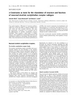
2.1. WAP proxy model
The WAP programming model is an extension of the world
wide web (WWW) programming model with a few enhance-
ments such as Push model and support for wireless telephony
application (WTA). In WAP 2.0, the WAP proxy is optional,
since the communication between the client and server can
be conducted using HTTP 1.1. However, deploying a proxy,
as shown in Figure 1, can optimize the communication pro-
cess and may offer mobile service enhancements, such as lo-
cation, privacy, and presence-based services. In addition, a
WAP proxy is necessary to offer Push functionality [1, 2].
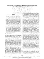
In the WAP 1.x configuration (Figure 2), the proxy, also
known as WAP gateway, is required to handle the proto-
col interworking between the client and the content server.
A WAP 1.x gateway essentially implements both the WAP
1.x and Internet protocol stacks within the same node. It
is used for protocol conversions between these two proto-
col stacks, and the conversion between text-based wireless
markup language (WML) documents in the Internet do-
main and binary-encoded bytecode in the wireless domain.
The WAP gateway communicates with the client using the
WAP 1.x protocols: WSP, WTP, wireless datagram protocol
(WDP), with data security provided by the wireless trans-
action layer security (WTLS) protocol, and it communicates
with the content server using the standard Internet protocols
(HTTP/TCP/IP), with data security provided by the trans-
port layer security (TLS) protocol.
Enhancement of WAP 2.0 Performance by Data Compression 59
2.2. WAP end-to-end security
Although WAP 1.x protocol conversion and content encod-
ing minimizes the air-interface traffic, and WAP 1.x can pre-
serve user data privacy and security using WTLS, WTLS can
only protect user data in transit over the wireless network
between the WAP gateway and the client at the mobile ter-
minal [14], while TLS is used to protect the user data in
transit over the Internet between the gateway and the con-
tent server. T he gateway, which translates messages from one
protocol to another, is a security gray zone for end-to-end ap-
plications because the cleartext data is temporar ily exposed
in its memory during the conversion. Although the conver-
sion happens in the memory of the gateway and is com-
pleted quickly, the concept of end-to-end security between
the WAP client and the content server is violated. This is not
acceptable for applications with strict security requirements,
such as bank and financial transactions and e-business, be-
cause it is analogous to allowing your ISP to process (and
inspect) the data of secure transactions. The only viable so-
lution that strictly guarantees end-to-end security [8]isto
collocate the gateway with the WAP server in a protected
network that is secured from the Internet, for example, by
afirewall.In[8], this alternative configuration was evaluated
under various IS-95 wireless links and Internet channel con-
ditions and compared against the standard configuration in
which the gateway is located at junction of the cellular net-
work and the Internet. Despite the feasibility of this alterna-
tive configuration, its drawbacks are also obvious. Aside from
content providers having to invest in the infrastructure and
to maintain their ow n gateways, the WAP clients also have
to be configured to switch gateways to access various secure
WAP a pplications. The latter, like having to switch ISPs when
accessing different web sites, is cumbersome and undesirable
for most users.
As WP-HTTP/WP-TCP are interoperable with HTTP/
TCP, there is no complex protocol conversion required be-
tween WAP 2.0 and the Internet protocols; therefore the
proxy is optional in WAP 2.0configurations.Eveninthe
presence of a proxy, strict end-to-end security can still be
guaranteed by implementing the proxy at the transport layer,
which enables it to support end-to-end TLS tunnels between
the clients and the WAP servers [15].
Although WAP 2.0 is an evolutionary step forward with
respect to WAP 1.x, if the data encoding mechanism em-
ployed by WAP 1.x at the gateway were not also employed
in WAP 2.0, the transmitted packets in WAP 2.0wouldbe
much larger than the encoded bytecode in WAP 1.x. To min-
imize the volume of data sent over the air, content coding
of the HTTP message body may be employed by the HTTP
client in the WAP terminal, and either at the HTTP server
or in the WAP Proxy [4]. To support this function, the WAP
Proxy must at least provide for deflate coding (data compres-
sion) as specified in [16]. Also, an encoding format known as
wireless binary extensible markup language (WBXML), sim-
ilar to WML in WAP 1.x, can be implemented at the WAP
proxy [17]. However, these solutions only guarantee end-to-
end security if a direct connection exists between the WAP
Web
server
WAE
HTTP
TLS
TCP
IP
Wired
WAP 2.0 proxy
Comp/decomp
WP-TCP
IP
ROHC
Wireless
TCP
IP
Wired
WAP
device
WAE
HTTP
TLS
Comp/decomp
WP-TCP
IP
ROHC
Wireless
Figure 3: Data compression proxy supporting end-to-end security
with TLS tunneling.
server and WAP client to support TLS tunneling. If the con-
tent coding were performed at the WAP proxy instead, a sim-
ilar end-to-end security problem as in WAP 1.x would still
exist.
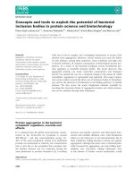
2.3. Proposed compression scheme
with enhanced security
In order to improve the performance of WAP 2.0 while guar-
anteeing end-to-end security via TLS, a novel proxy archi-
tecture, as shown in Figure 3, is proposed. The pro xy con-
nects to the WAP server using standard TCP over the Inter-
net and communicates with WAP clients using WP-TCP over
the wireless domain to optimize transport layer performance.
Thus end-to-end security can be strictly guaranteed by TLS
tunneling. To further improve the performance, an advanced
data compression scheme is introduced between the proxy
and client to reduce the packet size and conserve bandwidth
over the air interface. For applications that do not require
end-to-end security, the proposed proxy can also work as
a HTTP proxy that uses WP-HTTP between the proxy and
client above the compression scheme to further improve the
performance.
The proposed advanced data compression scheme com-
bines two separate compression processes: TCP content com-
pression and robust header compression (ROHC).
For evaluation purposes, content compression and de-
compression are accomplished using the deflate algorithm
[16], a lossless compression method used in “gzip” that com-
presses data using a combination of the LZ77 algorithm and
Huffman coding. Other lossless compression/decompression
algorithms can also be used. The compression and de-
compression operate in the TCP socket stream using in-
memory compression/decompression functions in the “zlib”
compression library [18, 19]. Since the content compres-
sion works in the transport layer, it compresses all higher-
layer headers, including the HTTP header. This compression
works better than when only HTTP content compression is
employed at WP-HTTP, and results in a maximum content
compression for IP packets. There are three options for the
content compression: no compression, reply compression,
and request and reply compression.
60 EURASIP Journal on Wireless Communications and Networking
WAP ser ver + g a tewayWireless channelWAP client
WAP
server
Internet
channel
omitted
WAP 1.x
gateway
WAP 2 p roxy
(content
compression)
Wireless
channel
(NS-2 emulator)
UDP
timer
TCP timer
(content
decompression)
WAP
phone
emulator
Figure 4: WAP 1.x and WAP 2.0 emulation test bed configuration.
ROHC has been studied extensively in the literature
[20, 21, 22], and will be used in all 3G cellular systems, which
can substantially improve spectrum efficiency and service
quality for IP services such as voice and video over the mo-
bile Internet. For evaluation purp oses, ROHC is simulated by
applying an appropriate compression ratio. The design and
implementation of ROHC are discussed in [23].
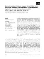
3. PERFORMANCE EVALUATION METHOD
3.1. Test bed configuration
The performance of the proposed proxy architecture is evalu-
ated using the test bed shown in Figure 4, for both versions of
WAP (1.x and 2.0), with different combinations of compres-
sion methods. Both of the test configurations use a proxy to
interconnect the wireless domain and Internet domain, and
the Internet section is identical to both. Since different In-
ternet delays resulting from various Internet conditions con-
tribute the same amount of additional delays to both config-
urations, a differential comparison is more appropriate for
performance comparison purposes. Consequently, the Inter-
netdomainisnotincludedinthetestbedasitisassumed
to contribute the same delay to all the test scenarios. Assum-
ing no delay and no packet losses over the Internet allows the
performance comparison to focus on the effects of the wire-
less channels. So the test bed is configured with a WAP server,
a WAP proxy (a WAP 1.x gateway for WAP 1.x, the proposed
compression proxy f or WAP 2.0), a WAP phone emulator
as client, and an emulated wireless channel connecting the
proxy to the client.
The network simulator 2 (ns-2) [24]isusedtoemu-
late the packet level behaviors of over narrowband IS-95 and
wideband CDMA2000 1xRTT wireless channels. The emu-
lated wireless channel consists of two nodes, a base station
and a mobile client. By attaching the tap agents, the nodes are
capable of introducing live traffic into the ns-2 simulator and
injecting traffic from the simulator into the live network after
the traffic has been subject to appropriate delays and losses.
Due to the header added in ns-2 emulation, the Ethernet
maximum transmission unit (MTU) is reduced from 1500
bytes to 1400 bytes. The IP packets captured from the live
traffic by the node are first fragmented at link layer (LL) and
then transmitted to the other node. The received fragments
are then defragmented in the node and injected back to live
traffic. Each fragment is sent every 20 milliseconds with 168
bits and 3048 bits, respectively, in accordance with the IS-
95 and CDMA2000 1xRTT standards. With additional CRC
and encoding tail bits, the maximum user data transmis-
sion rate in the emulation channel is 9.6 Kbps for IS-95, and
153.6 Kbps for CDMA2000 1xRTT. The wireless channel de-
lay is set to be 1 millisecond, and the TCP options are set
based on the mandatory WP-TCP requirements on both the
client and the proxy server, for example, window scale op-
tion, large initial window, and selective acknowledgement are
all supported, and the maximum congestion window size is
set as 64 KB. The packet group size for class 2 WTP is set
with the default value of 1405 bytes [25]. Since all practical
parameter values and typical WML pages from real example
sites are used in the simulations, the results closely represent
the real-life WAP user experience.
For data services in both the IS-95 and the CDMA2000
networks, data is framed into 20 milliseconds blocks for
transmission over the physical layer traffic channel [26, 27,
28]. Therefore, the frame error rate (FER) or block error
rate (BLER) are more suitable measures of the link quality
as seen by the upper layers than BER, since the use of inter-
leaving and forward error correction coding techniques can
lead to the detection and recovery of some bit errors. Sev-
eral papers have used first-order Markov chains to model
block error processes in transmissions over wireless chan-
nels [29, 30, 31]. In certain sets of parameters, the Markov
chain leads to a unique stationary distribution, which means
a uniform FER over time. Therefore, a specific FER is em-
ployed as a measure of the transmission quality in the exper-
iments to evaluate performance under each given set of wire-
less channel conditions. The FER parameter represents the
unrecoverable error rate after the FEC decoder. The frame
is considered erroneous and needs to be retransmitted when
Enhancement of WAP 2.0 Performance by Data Compression 61
error occurs that the FEC decoder fails to correct. A selective-
repeat (SR) automatic-repeat request (ARQ) error recovery
mechanism is employed at the LL for the LL fragments. This
provides a reliable connection between the compression and
decompression processes such that loss of synchronization
due to lost packets is not an issue here. ROHC over the wire-
less network is simulated by giving the first LL fragment a
bigger size than the others. This assumes an average header-
compression ratio that is statistically stationary and fixed in
alongrun.
3.2. Performance evaluation criteria
The performance metric considered is the average end-to-
end access time or round-trip delay for a sample WML file
[32]. WML files are used in our test since we want to com-
pare the WAP 2.0 configurations with WAP 1.x protocol
stack. While WAP 2.0continuesitssupportforWAP1.x-
based WML, the WAP 1.x stack does not recognize the new
wireless application environment (WAE) definitions in WAP
2.0, such as extensible HTML (XHTML). In the experiments,
several WML files were transferred and the average round-
trip delay was obtained. The a ctual access time (AT) in-
cludes the wireless transmission time (WTT, including LL
retransmissions), Internet transmission time (ITT, including
retransmissions if applicable), and the system processing de-
lay (PD); that is,
AT = WTT + ITT + PD, (1)
where PD consists of the queuing delay (QD) at the WAP
server and proxy and the processing time (PT) at the server,
proxy, and client, given by
PD = QD
Server
+QD
Proxy
+PT
Server
+PT
Proxy
+PT
Client
.
(2)
In order to evaluate the performance improvements due
to the data compression scheme, differential comparisons are
used and the access time differences (ATDiff)ismeasuredfor
evaluation purposes instead of the absolute AT values.
For WAP 2.0, the AT is the elapsed time b etween when
the client makes a request and when it successfully receives
(and decompresses if necessary) a reply at the TCP socket
layer. For WAP 1.x, the sessions are based on class 2 WTP
transactions, which is the basic request/response and the
most commonly used transaction service [25]. It is connec-
tion oriented with a reliable invoke message with one reliable
result message. WTP is over UDP in our experiments. In this
case, the AT is the elapsed time between the invoke and the
acknowledgment (ACK), both at the client side. In all cases,
ITT is a common element of AT that offsets each other in
computing ATDiff.
To facilitate the evaluation, wireless access time (WAT) is
defined as AT less ITT, or the sum of the wireless transmis-
sion time and the processing delay, that is,
WAT
= WTT +PD, (3)
the WAT of WAP 2.0 configuration without compression is
used as the basis for comparison purposes. All other config-
urations are evaluated by comparing the ATDiffs, which are
the WATs of other configurations minus the WAT of uncom-
pressed WAP 2.0.
ATDiff = AT
otherconf
− AT
nocomp WAP 2
= WAT
otherconf
− WAT
nocomp WAP 2
.
(4)
3.3. Assumptions and limitations
The wireless channel implemented in ns-2 closely simulates
the link layer behavior of IS-95 and CDMA2000 1xRTT with
a specific FER. However, due to the constraints of our test
bed configuration and wireless channel emulation, our ex-
periments are subject to cer tain assumptions and limitations.
They are summarized as follows.
(i) The emulated wireless channel is used solely by the
WAP application during the experiments. There could
be other applications sharing the channel in real life.
Extra delay would be incurred if the channel was
shared with other trafficstreams.
(ii) It is assumed that only one WAP session is in progress
at any given time; that is, no new WAP request is gen-
erated until the result from the former request is re-
ceived. This results in no queuing delays at the WAP
server or the WAP proxy.
(iii) A fixed link layer FER is assumed on both the uplink
and downlink. In real life, the traffic and propagation
conditions in the CDMA channel may cause fluctu-
ations in noise and interference levels and hence the
FER, and the uplink and downlink may have different
FERs.
(iv) The content compression and decompression are im-
plemented on Pentium PCs. The processing time could
be lower in real gateways employing more powerful
processors, and higher in mobile terminals with less
powerful processors.
(v) Not all optimizations suggested by WP-TCP are imple-
mented due to the constraints of the test bed environ-
ment. Handoff delays have not been considered.
4. PERFORMANCE RESULTS
4.1. WAP enhancement with compression scheme
The performance is e valuated by comparing the ATDiffsof
different compression options under various wireless chan-
nel conditions. WAP 1.x was also tested as a comparison and
as an indication of the performance of WAP binary XML
(WBXML) in WAP 2.0 since WBXML employs similar en-
coding and decoding method as binary WML. The WAT of
WAP 2.0 without compression (WAT
nocomp WAP 2
)forboth
IS-95 and CDMA2000 1xRTT wireless channels, which will
be used as the basis for further comparisons, are shown in
Figure 5.
62 EURASIP Journal on Wireless Communications and Networking
40201051
Frame error rate (%)
35
40
45
50
55
60
65
70
75
80
×10
2
Wireless access time (ms)
IS-95
40201051
Frame error rate (%)
160
170
180
190
200
210
220
230
240
250
Wireless access time (ms)
CDMA2000 1 × RTT
Figure 5: Wireless access time of WAP 2.0 without compression.
Table 1: WAP processing delays.
WAP 1 .x
WAP 2 .0 (HTTP, TCP/IP)
No compression Reply compression Request & reply compression
180.05 ms 4.02 ms 6.69 ms 11.51 ms
The transmission times over the LAN interconnecting
the test bed computers were measured and the processing de-
lays (PD) (Ta ble 1 ) were estimated by subtracting the trans-
mission times from the total delays. The PD in WAP 1.x
comes mainly from the protocol conversion and data encod-
ing and decoding at the gateway and client. Result shows that
in good conditions the PD of WAP 1.x is much larger than
that of WAP 2.0, which implies that WAP 2.0 HTTP/TCP/IP
stack is more efficient. The compression process only c auses
a processing delay of several milliseconds.
Since IP is supported in IS-95 but not in GSM and most
other narrowband network bearers on which WAP 1.x pro-
tocol stack employing WTP and WDP has to be used, WAP
2.0 with TCP/IP support is unlikely to be used in narrow-
band networks. We briefly compare the results in IS-95 as an
indication of the effectiveness of WAP 2.0 data compression
scheme for IP enabled narrowband wireless networks and fo-
cus our results on the CDMA2000 1xRTT wireless channel.
Results for an emulated IS-95 channel with a maximum
bandwidth of 9.6 Kbps presented in Figure 6 show that the
WAT of WA P 1. x is 2.72–6.04 seconds less than that of WAP
2.0 employing TCP/IP when no data compression is used,
which corresponds to 71%–80% less than WAT
nocomp WAP 2
from Figure 5. This clearly shows the advantage of WAP
1.x over TCP/IP in low-bandwidth networks. Figure 6 shows
that by applying the proposed advanced data compression
scheme, the performance of WAP 2.0canbeimprovedto
match that of WAP 1.x.
Over an emulated CDMA2000 1xRTT channel with max-
imum bandwidth of 153.6Kbps,WAP2.0outperformsWAP
1.x even if no compression is applied, with WAT reduced by
78.4 milliseconds and 25.7 milliseconds at 1% and 40% FER,
respectively (Figure 7), corresponding to 32.5% and 9% im-
provement on WAT compared with WAT
nocomp WAP 2
. This is
due to the long processing delay for protocol conversions in
the WAP 1.x gateway and client. The lower processing time
of HTTP/TCP makes them more appropriate for high-speed
networks. Since the transmitted data traffic is much h igher
than that in WAP 1.x, the WAP 2.0performancedegrades
when FER is high due to more packet retransmissions.
The content compression brings the most performance
enhancements by reducing the transmission delays by 73.6–
117 milliseconds or 44%–46% less than WAT
nocomp WAP 2
at
1% and 40% FER (Figure 8) because text-based WML (or
XHTML) files yield high compress ratios. The compressed
packets need much fewer LL frag ments to transfer. When
ROHC is employed, another 3–7 milliseconds or 3% reduc-
tion in WAT can be achieved over content compression. Re-
sults also show that reply compression works even better than
the combined request and reply compression. This can be ex-
plained as follows: because the request packet is quite small,
therefore the data compression scheme does not give much
gain, and the transmission time saved from the reduced size
is smaller than the processing delay int roduced by the re-
quest compression. The results show that WAP 2.0ismore
suitable for the high-speed wireless networks, and the com-
pression scheme can reduce WAT by over 76 mil l iseconds at
1% and 120 milliseconds at 40% FER, corresponding to over
45% improvement in WAT, but request compression is not
appropriate for use over a high-speed wireless network.
Enhancement of WAP 2.0 Performance by Data Compression 63
40201051
Frame error rate (%)
−65
−60
−55
−50
−45
−40
−35
−30
−25
×10
2
Access time difference (ms)
Reply comp.
Request & reply comp.
Reply comp.
w/ ROCH
WAP 1.x
Request & reply
comp. w/ ROCH
Figure 6: WAP performance in IS-95.
40201051
Frame error rate (%)
−150
−100
−50
0
50
100
Access time difference (ms)
WAP1.x
Reply comp.
Reply comp. w/ ROCH
Reply & request
comp. w/ ROCH
Reply & request comp.
Figure 7: WAP performance in CDMA2000 1xRTT.
The above results are obtained based on data compres-
sions and protocol conversions at the processing speeds of
the test bed computers. With a less powerful mobile terminal
processor, there will be some extra processing delay for both
protocol conversion and content encoding in WAP 1.x and
the proposed data compression and decompression process
in WAP 2.0. Considering the complexity of WAP 1.x protocol
conversion, it is reasonable to assume that this has a higher
processing delay than the WAP 2.0 content compression and
decompression process. Further more, in WAP 2.0, the extra
processing delay for content compression and decompres-
sion is generally much smaller compared with the reduct ion
in transmission time made possible by content compression.
Therefore, although the numerical results are specific to the
40201051
Frame error rate (%)
−130
−120
−110
−100
−90
−80
−70
Access time difference (ms)
Reply comp.
Request & reply comp. Request & reply
comp. w/ ROCH
Reply comp. w/ ROCH
Figure 8: The performance of WAP 2.0 with compression in
CDMA2000 1xRTT.
test bed equipment, our general observations regarding the
effectiveness of the proposed proxy architecture supporting
data compression, based on the experimental results, remain
valid.
4.2. WAP 2.0: proxy versus direct connection
In WAP 2.0, a direct TCP connection can be used to provide
an end-to-end HTTP/1.1service.However,usingaproxy,
which leads to a split-TCP approach [33], can optimize and
enhance the connection between the wireless domain and the
Internet domain.
In the case of a direct connection, the optimizations pro-
vided by WP-TCP and WP-HTTP over wireless links may
not be available as the wireless profiled options for the re-
spective protocols may not be implemented at the servers. In
the mobile networks with bursty errors and high bit error
rates, relatively long delays and variable bandwidth, the con-
gestion control mechanism of standard TCP adversely affects
its perform ance, for example, packet error is regarded as con-
gestion, which leads to reduction of congestion window and
slow recovery. In addition, two major factors also contribute
to the increase in the access time.
First, the split-TCP approach using a proxy shields prob-
lems associated with wireless links from the wireline Inter-
net and vice versa. The direct connection causes error prop-
agation between the Internet and wireless domains. It can be
proved by a simple calculation. Let the packet drop rates and
transmission times over the Internet and wireless domain be
ε
1
, t
1
and ε
2
, t
2
, respectively, in the forward direction and as-
sume perfect feedback with no packet drops in the reverse di-
rection. In a direct connection, the overall access time (AT) is
the process delay (PD) plus direct transmission time (t
direct
):
AT
direct
= PD + t
direct
= PD+
t
1
+ t
2
1 − ε
1
1 − ε
2
. (5)
64 EURASIP Journal on Wireless Communications and Networking
40201051
Frame error rate (%)
50
100
150
200
250
300
350
400
450
500
Wireless session delay (ms)
No comp.
Request & reply comp.
Reply comp.
Request & reply
comp. w/ ROCH
Reply comp. w/ ROCH
Figure 9: Direct connection wireless session delay in IS-95.
If a proxy is present, the AT is given by
AT
pro xy
= PD+ITT+WTT
= PD+
t
1
1 − ε
1
+
t
2
1 − ε
2
= PD+
t
1
+ t
2
−
ε
1
t
2
+ ε
2
t
1
1 − ε
1
1 − ε
2
.
(6)
It is obvious that AT
pro xy
< AT
direct
. The proxy facilitates
independent error recovery over the wireless and Internet
domains so that error-free data is always passed from one
domain to the next. Thus no retra nsmission needs to pass
through both domains.
Second, TCP is a reliable, connection-oriented transport
layer protocol. For each TCP session, there is a 3-way hand-
shaking for the TCP connection establishment and 4-way
data exchange for the TCP connection termination process.
If there is no proxy, the WAP client has to establish a separate
TCP session for each different WAP serv er. With a proxy, the
WAP client can maintain a long-lived socket with the proxy,
thus eliminating extra connection and termination delays in
the wireless domain. The wireless session delay (WSD) is
used to represent these delays in our experiments. The WSD
is defined as the time delay due to TCP connection e stablish-
ment and termination in the wireless networks.
Over the low-bandwidth IS-95 channel supporting
TCP/IP, experiment results in Figure 9 show that the WSDs
are quite high if direct connections are used, 234 milliseconds
at 1% FER and 483 milliseconds at 40% FER, respectively.
If content compression is employed, the WSD is reduced by
28% at 1% FER and 52% at 40% FER. Figure 9 also indicates
that ROHC in the wireless domain can give a 40% reduction
in WSD over the content compression scheme due to the re-
duced header size in the handshaking packets.
With the WAP 2.0 TCP/IP stack, in CDMA2000 1xRTT
wireless channels, WSDs are around 70 milliseconds at 1%
40201051
Frame error rate (%)
50
55
60
65
70
75
80
85
90
100
Wireless session delay (ms)
No comp.
Request & reply comp.
Reply comp.
Request & reply
comp. w/ ROCH
Reply comp.
w/ ROCH
Figure 10: Direct connection wireless session delay in CDMA2000
1xRTT.
FER and 95 milliseconds at 40% FER (Figure 10). WSDs
are almost the same with or without the data compression
scheme. Also, ROHC gives nearly no benefit in reducing the
WSD. This is because the TCP handshaking and termination
packets are quite small, a nd they can be transmitted in one
LL fragment in all cases.
Note that the WSDs presented above are obtained over an
error-free Internet in our test environment. In practice, pack-
ets may be dropped over the Internet due to congestion, in
which case the WSD of direct connections will become even
higher due to possible retransmissions of handshaking pack-
ets c aused by the Internet and wireless losses. These results
clearly illustrate the performance enhancements provided by
the proxy made possible by setting up long-lived connec-
tions, especially when the clients frequently switch applica-
tions hosted on different WAP servers.
Since a proxy is usually maintained by a wireless service
provider, beside the above-mentioned advantages, a proxy is
required for WAP Push operations and may offer location,
privacy, and presence-based services to mobile users. Fur-
thermore, the caching capability at the proxy can provides
better service experience to end users, especially for low-end
WAP phones.
5. CONCLUSIONS
We have presented a novel proxy architecture employing ad-
vanced data compression schemes to minimize air-interface
traffic thus significantly improving the access time perfor-
mance of WAP 2.0, w hile ensuring that end-to-end secu-
rity can be strictly guaranteed using TLS tunneling. Most of
the access time reduction is contributed by the reply con-
tent compression, while ROHC can offer further improve-
ments. Experimental results show that WAP 1.x is optimized
for narrowband networks. However, in narrowband IS-95
networks with IP support, the proposed scheme can reduce
Enhancement of WAP 2.0 Performance by Data Compression 65
WAP 2.0 access time to the same level as WAP 1.x. In wide-
band CDMA2000 1xRTT networks, WAP 2.0outperforms
WAP 1.x in access time even without data compression, and
the advanced compression schemes can reduce access time
by 75–120 milliseconds in the test bed network, correspond-
ing to over 45% improvement on WAT. Although optional
in WAP 2.0, the proxy not only prevents the error propa-
gations between wired and wireless domains, but also sig-
nificantly reduces the wireless session delays due to TCP
connection establishments by enabling long-lived connec-
tions to be set up between the proxy and wireless termi-
nals. With the deployment of IP-enabled high-speed 2.5G
and 3G networks, WAP 2.0 will facilitate further convergence
between wireless networks and the Internet, and the pro-
posed data compression scheme can bring huge performance
benefits.
ACKNOWLEDGMENTS
This paper is based in part on a paper presented at IEEE
WCNC, New Orleans, Louisiana, March 2003. This work was
supported by grants from TELUS Mobility and the Advanced
Systems Institute of British Columbia, and by the Canadian
Natural S ciences and Engineering Research Council under
Grant no. CRD 247855-01.
REFERENCES
[1] WAP Forum, “Wap architecture specification,” version 12-
July-2001, />[2] WAP Forum, “Wap 2.0 technical white paper,” January 2002.
[3] WAP Forum, “Wireless profiled TCP,” version 31-March-
2001.
[4] WAP Forum, “Wireless profiled HTTP,” version 29-March-
2001.
[5] P. Stuckmann and C. Hoymann, “Performance evaluation
of WAP-based applications over GPRS,” in Proc. IEEE Inter-
national Conference on Communications (ICC ’02), vol. 5, pp.
3356–3360, New York, NY, USA, May 2002.
[6] A. Andreadis, G. Benelli, G. Giambene, and B. Marzucchi,
“Performance analysis of the WAP protocol over GSM-SMS,”
in Proc. IEEE International Conference on Communications
(ICC ’01), vol. 2, pp. 467–471, Helsinki, Finland, June 2001.
[7] S. Lee and N O. Song, “Experimental WAP (wireless applica-
tion protocol) traffic modeling on CDMA based mobile wire-
less network,” in Proc. IEEE VTS 54th Vehicular Technology
Conference (VTC ’01), vol. 4, pp. 2206–2210, Atlantic City, NJ,
USA, October 2001.
[8] S.SheoranandV.C.M.Leung,“EvaluationofWAPnetwork
configuration supporting enhanced security,” in Proc. I nter-
national Conference on Consumer Electronics (ICCE ’02),pp.
78–79, Los Angeles, Calif, USA, June 2002.
[9] P. Ashley, H. Hinton, and M. Vandenwauver, “Wired ver-
sus wireless security: the internet, WAP and iMode for E-
commerce,” in Proc. 17th Annual Computer Security Appli-
cations Conference (ACSAC ’01), pp. 296–306, New Orleans,
La, USA, December 2001.
[10] E K. Kwon, Y G. Cho, and K J. Chae, “Integrated transport
layer security: end-to-end security model between WTLS and
TLS,” in Proc. 15th International Conference on Information
Networking (ICOIN ’01), pp. 65–71, Beppu City, Oita, Japan,
January 2001.
[11] ISO/IEC JTC1/SC29/WG11 N4668, “Overview of the MPEG-
4 standard,” March 2002.
[12] ITU-T Recommendation H.263, “Video coding for low bit
rate communication,” February 1998.
[13] ITU-T Recommendation V.42bis, “Data compression proce-
dures for data circuit-terminating equipment (DCE) using er-
ror correction procedures,” January 1990.
[14] WAP Forum, “Wap transport layer end-to-end security,” ver-
sion 28-June-2001.
[15] WAP Forum, “Wap TLS profile and tunneling,” version 11-
April-2001.
[16] P. Deutsch, “Deflate compressed data format specification,”
version 1.3, May 1996, RFC1950.
[17] WAP Forum, “Binary XML Content Format Specification,”
Version 1.3, July 25, 2001.
[18] P. Deutsch, “ZLIB compressed data format specification,” ver-
sion 3.3, May 1996, RFC1950.
[19] Zlib version 1.1.4, March 2002.
[20] C. Bormann, C. Burmeister, M. Degemark, et al., “Robust
header compression (ROHC),” July 2001, RFC3095.
[21] M. Degermark, “Requirements for robust IP/UDP/RTP
header compression,” June 2001, RFC3096.
[22] M. Degermark, H. Hannu, L. Jonsson, and K. Svanbro, “Eval-
uation of CRTP performance over cellular radio links,” IEEE
Pers. Commun., vol. 7, no. 4, pp. 20–25, 2000.
[23] L E. Jonsson and P. Kremer, “ROHC implementer’s guide,”
IETF Internet draft, <draft-ietf-rohc-rtp-impl-guide-04.txt>,
September 23, 2003.
[24] The network simulator ns 2, “version 2.1b9,” .
edu/nsnam/ns.
[25] WAP Forum, “Wireless Transaction protocol,” version 10-
July-2001.
[26] TIA/EIA Interim Standard-95, “Mobile station—base station
compatibility standard for dual-mode wideband spread spec-
trum cellular system,” July 1993.
[27] 3GPP2 C.S0002-C, “Physical layer standard for cdma2000
spread spectrum systems, Release C,” Version 1.0, May 28,
2002.
[28] 3GPP2 C.S0003-C, “Medium Access Control (MAC) Stan-
dard for cdma2000 Spread Spectrum Systems, Release C,” Ver-
sion 1.0, May 28, 2002.
[29] C. C. Tan and N. C. Beaulieu, “On first-order Markov mod-
eling for the Rayleigh fading channel,” IEEE Trans. Commun.,
vol. 48, no. 12, pp. 2032–2040, 2000.
[30] M. R. Hueda, “On fi rst-order Markov modeling for block er-
rors on fading channels,” in Proc. IEEE 55th Vehicular Technol-
og y Conference (VTC ’02), vol. 3, pp. 1336–1339, Birmingham,
Ala, USA, May 2002.
[31] M. R. Hueda, “On the Markovian approximation for block-
errors in DS-CDMA transmissions over slow fading channels
with multicarrier transmit diversity,” in IEEE International
Conference on Communications (ICC ’02), vol. 2, pp. 737–741,
New York, NY, USA, May 2002.
[32] B. Eged, T. Dezso, and F. Egedi, “S erver side round-trip
delay measurements in WAP environments,” in Proc. 18th
IEEE Instrume ntation and Measurement Technology Confer-
ence (IMTC ’01), vol. 1, pp. 525–529, Budapest, Hungary, May
2001.
[33] A. V. Bakre and B. R. Badrinath, “Handoff and systems sup-
port for indirect TCP/IP,” in Proc. 2nd Symposium on Mobile
and Location-Independent Computing, pp. 11–24, Ann Arbor,
Mich, USA, April 1995.
66 EURASIP Journal on Wireless Communications and Networking
Zhanping Yin received his B.Eng. and
M.Eng. degrees in optical instrument from
Tianjin University, Tianjin, China, and the
M.A.Sc. degree in electrical engineering
from the University of British Columbia,
Vancouver, Canada, in 1992, 1995, and
2002, respectively. He is currently work-
ing toward the Ph.D. degree in the Depart-
ment of Electrical and Computer Engineer-
ing, University of British Columbia, Van-
couver, Canada. His current research interests are in wireless com-
munications protocols including WAP, WLAN, WPAN, UWB, and
cross-layer design.
Victor C. M. Leung received the B.A.Sc.
(with honors) and Ph.D. degrees, both in
electrical engineering, from the University
of British Columbia (UBC) in 1977 and
1981, respectively. He received the APEBC
Gold Medal as the Head of the Graduat-
ing Class in the Faculty of Applied Science,
and the Natural Sciences and Engineering
Research Council Postgraduate Scholarship.
From 1981 to 1987, Dr. Leung was a Se-
nior Member of Technical Staff at MPR Teltech Ltd. In 1988, he
was a Lecturer in the Department of Electronics, the Chinese Uni-
versity of Hong Kong. He returned to UBC in 1989 as a faculty
member, where he is a Professor in the Department of Electrical
and Computer Engineering, holder of the TELUS Mobility Indus-
trial Research Chair in Advanced Telecommunications Engineer-
ing, and Associate Head for Graduate Affairs. His research inter-
ests are in the areas of architectural and protocol design and per-
formance analysis for computer and telecommunication networks,
with applications in satellite, mobile, personal communications,
and high-speed networks. Dr. Leung is a Fellow of IEEE, a Mem-
ber of ACM, an Editor of the IEEE Transactions on Wireless Com-
munications, and an Associate Editor of the IEEE Transactions on
Vehicular Technology.