Báo cáo hóa học: " Generic Multimedia Multimodal Agents Paradigms and Their Dynamic Reconfiguration at the Architectural Level" potx
Bạn đang xem bản rút gọn của tài liệu. Xem và tải ngay bản đầy đủ của tài liệu tại đây (1.47 MB, 20 trang )
EURASIP Journal on Applied Signal Processing 2004:11, 1688–1707
c
2004 Hindawi Publishing Corporation
Generic Multimedia Multimodal Agents Paradigms
and Their Dynamic Reconfiguration
at the Architectural Level
H. Djenidi
D
´
epartement de G
´
enie
´
Electrique,
´
EcoledeTechnologieSup
´
erieure, Universit
´
eduQu
´
ebec, 1100 Notre-Dame Ouest,
Montr
´
eal, Qu
´
ebec, Canada H3C 1K3
Email:
Laboratoire PRISM, Universit
´
e de Versailles Saint-Quentin-en-Yvelines, 45 Avenue des
´
Etats-Unis, 78035 Versailles Cedex, France
S. Benarif
Laboratoire PRISM, Universit
´
e de Versailles Saint-Quentin-en-Yvelines, 45 Avenue des
´
Etats-Unis, 78035 Versailles Cedex, France
Email:
A. Ramdane-Cherif
Laboratoire PRISM, Universit
´
e de Versailles Saint-Quentin-en-Yvelines, 45 Avenue des
´
Etats-Unis, 78035 Versailles Cedex, France
Email:
C. Tadj
D
´
epartement de G
´
enie
´
Electrique,
´
EcoledeTechnologieSup
´
erieure, Universit
´
eduQu
´
ebec, 1100 Notre-Dame Ouest,
Montr
´
eal, Qu
´
ebec, Canada H3C 1K3
Email:
N. Levy
Laboratoire PRISM, Universit
´
e de Versailles Saint-Quentin-en-Yvelines, 45 Avenue des
´
Etats-Unis, 78035 Versailles Cedex, France
Email: nle
Received 30 June 2002; Revised 22 January 2004
The multimodal fusion for natural human-computer interaction involves complex intelligent architectures which are subject to
the unexpected errors and mistakes of users. These architectures should react to events occurring simultaneously, and possibly
redundantly, from different input media. In this paper, intelligent agent-based generic architectures for multimedia multimodal
dialog protocols are proposed. Global agents are decomposed into their relevant components. Each element is modeled separately.
The elementary models are then linked together to obtain the full architecture. The generic components of the application are then
monitored by an agent-based expert system which can then perform dynamic changes in reconfiguration, adaptation, and evolu-
tion at the architectural level. For validation purposes, the proposed multiagent architectures and their dynamic reconfiguration
are applied to practical examples, including a W3C application.
Keywords and phrases: multimodal multimedia, multiagent architectures, dynamic reconfiguration, Petri net modeling, W3C
application.
1. INTRODUCTION
With the growth in technology, many applications support-
ing more transparent and flexible human-computer inter-
actions have emerged. This has resulted in an increasing
need for more powerful communication protocols, espe-
cially when several media are involved. Multimedia multi-
modal applications are systems combining two or more nat-
ural input modes, such as speech, touch, manual gestures,
lip movements, and so forth. Thus, a comprehensive com-
mand or a metamessage is generated by the system and sent
to a multimedia output device. A system-centered definition
of multimodality is used in this paper. Multimodality pro-
vides two striking features which are relevant to the desig n of
Dynamic Reconfiguration of Multimodal Generic Architectures 1689
multimodal system software:
(i) the fusion of different types of data from various input
devices;
(ii) the temporal constraints imposed on information pro-
cessing to/from input/output devices.
Since the development of the first rudimentary but workable
system, “Put-that-there” [1],whichprocessesspeechinpar-
allel with manual pointing, other multimodal applications
have been developed [2, 3, 4]. Each application is based on a
dialog architecture combining modalities to match and elab-
orate on the relevant multimodal information. Such appli-
cations remain strictly based on previous results, however,
and there is limited synergy among parallel ongoing efforts.
Today, for example, there is no agreement on the generic ar-
chitectures that support a dialog implementation, indepen-
dently of the application type.
The main objective of this paper is twofold.
First, we propose generic architectural paradigms for an-
alyzing and extracting the collective and recurrent proper-
ties implicitly used in such dialogs. These paradigms use
the agent architecture concept to achieve their function-
alities and unify them into generic structures. A software
architecture-driven development process based on architec-
tural styles consists of a requirement analysis phase, a soft-
ware architecture phase, a design phase, and a maintenance
and modification phase. During the software architectural
phase, the system architecture is modeled. To do this, a mod-
eling technique must be chosen, then a software architectural
style must be selected a nd instantiated for the concrete prob-
lem to be solved. The architecture obtained is then refined
either by adding details or by decomposing components or
connectors (recursively, through modeling, choice of a style,
instantiation, and refinement). This process should result in
an architecture which is defined, abstract, and reusable. The
refinement produces a concrete architecture meeting the en-
vironmental requirements, the functional and nonfunctional
requirements, and all the constraints on dynamic aspects as
well as on static ones.
Second, we study the ways in which agents can be intro-
duced at the architectural level and how such agents improve
some quality attributes by adapting the initial architecture.
Section 2 gives an overview and the requirements of
multimedia multimodal dialog architecture (MMDA) and
presents generic multiagent architectures based on the pre-
vious synthesis. Section 3 introduces the dynamic reconfigu-
ration of the MMDA. This reconfiguration is performed by
an agent-based expert system. Section 4 illustrates the pro-
posed MMDA with a stochastic, timed, colored Petri net
(CPN) example [5, 6, 7] of the classical “copy and paste” op-
erations and il lustrates in more detail the proposed generic
architecture. This section also shows the suitability of CPN
in comparison with another transition diagram, the aug-
mented tr ansition network (ATN). A second example shows
the evolution of the previous MMDA when a new modality
is added, and examines the component reconfiguration as-
pects of this addition. Section 5 presents, via a multimodal
Web browser interface adapted for disabled individuals, the
novelty of our approach in terms of ambient intelligence.
This interface uses the fusion engine modeled with the CPN
scheme.
2. GENERIC MULTIMEDIA MULTIMODAL
DIALOG ARCHITECTURE
In this section, an int roduction to multimedia multimodal
systems provides a general survey of the topics. Then, a syn-
thesis brings together the overview and the requirements of
the MMDA. The proposed generic multiagent architectures
are described in Section 2.3.
2.1. Introduction to multimedia multimodal systems
The term “multimodality” refers to the ability of a system
to make use of several communication channels during user-
system interactions. In multimodal systems, information like
speech, pen strokes and touches, eye gaze, manual gestures,
and body movements is produced from user input modes.
These data are first acquired by the system, then they are
analyzed, recognized, and interpreted. Only the resulting in-
terpretations are memorized and/or executed. This ability to
interpret by combining parallel information inputs consti-
tutes the major distinction between multimodal and multi-
media systems. Multimedia systems are able to obtain, stock,
and restore different forms of data (text, images, sounds,
videos, etc.) in storage/presentation devices (hard drive, CD-
ROM, screen, speakers, etc.). Modality is an emerging con-
cept combining the two concepts of media and sensory data.
The phrase “sensor y data” is used here in the context of
the definition of perceptions: hearing, touch, sight, and so
forth [8]. The set of multimedia multimodal systems consti-
tutes a new direction for computing, provides several possi-
ble paradigms which include at least one recognition-based
technology (speech, eye gaze, pen strokes and touches, etc.),
and leads to applications which are more complex to manage
than the conventional Windows interfaces, like icons, menus,
and pointing devices.
There are two types of multimodality: input multimodal-
ity and output multimodality. The former concerns interac-
tions initiated by the user, while the latter is employed by the
system to return data and present information. The system
lets the user combine multimodal inputs at his or her conve-
nience, but decides which output modalities are better suited
to the reply, depending on the contextual environment and
task conditions.
The literature provides several classifications of modali-
ties. The first type of taxonomy can be credited to Card et
al. [9]andBuxton[10], who focus on physical devices and
equipment. The taxonomy of Foley et al. [11] also classifies
devi ces and equipment, but in terms of their tasks rather than
their physical attributes. Frohlich [12] includes input and
output interfaces in his classification, while Bernsen’s [13]
proposed taxonomy is exclusively dedicated to output inter-
faces. Coutaz and Nigay have presented, in [ 14], the CARE
properties that chara cterize relations of assignment, equiv-
alence, complementarity, and redundancy between modali-
ties.
1690 EURASIP Journal on Applied Signal Processing
Table 1: Interaction systems.
Engagement Distance Type of system
Conversation Small High-level language
Conversation Large Low-level language
Model world Small Direct manipulation
Model world Large Low-level world
For output multimodal presentations, some systems al-
ready have their preprogrammed responses. But now, re-
search is focusing on more intelligent interfaces which have
the ability to dynamically choose the most suitable output
modalities depending on the current interaction. There are
two main motivations for multimedia multimodal system
design.
Universal access
A major motivation for developing more flexible multimodal
interfaces has been their potential to expand the accessibility
of computing to more diverse and nonspecialist users. There
are significant individual differences in people’s ability to use,
and their preferences for using, different modes of commu-
nication, and multimodal interfaces are expected to broaden
the accessibility of computing to users of di fferent ages, skill
levels, and cultures, as well as to those with impaired senses
or impaired motor or intellectual capacity [3].
Mobility
Another increasingly impor t ant advantage of multimodal in-
terfaces is that they can expand the viable usage context to
include, for example, natural field settings and computing
while mobile [15, 16]. In particular, they permit users to
switch modes as needed during the changing conditions of
mobile use. Since input modes can be complementary along
many dimensions, their combination within a multimodal
interface provides broader utility across varied and changing
usage contexts. For example, using the voice to send com-
mands during movement through space leaves the hands free
for other tasks.
2.2. Multimodal dialog architectures:
overview and requirements
A basic MMDA gives the user the option of deciding which
modality or combination of modalities is better suited to the
particular task and environment (see examples in [15, 16]).
The user can combine speech, pen strokes and touches, eye
gaze, manual gestures, and body postures and movements via
input dev ices (key pad, tactile screen, stylus, etc.) to dialog in
a coordinated way with multimedia system output.
The environmental conditions could lead to more con-
strained architectures which have to remain adaptable dur-
ing periods of continuous change caused by either an ex-
ternal disturbance or the user’s actions. In this context, an
initial framework is introduced in [ 17] to classify interac-
tions which consider two dimensions (“engagement” and
“distance”), and decomposes the user-system dialog into four
types (Table 1).
Dialog architecture requirements
Time sensitivity Parallelism Asynchronicity
Semantic
information
level
Pattern of operations sets
for equivalent, complementary,
specialized, and/or redundant fusion
Feature
fragment
level
Stochastic knowledge Semantic knowledge
Figure 1: The main requirements for a multimodal dialog architec-
ture (→:usedby).
“Engagement” char acterizes the level of involvement of
the user in the system. In the “conversation” case, the user
feels that an intermediary subsystem performs the task, while
in the “model world” case, he can act directly on the system
components. “Distance” represents the cognitive effort ex-
pended by the user.
This framework embodies the idea that two kinds of mul-
timodal architectures are possible [18]. The first makes fu-
sions based on signal feature recognition. The recognition
steps of one modality guide and influence the other modali-
ties in their own recognition steps [19, 20]. The second uses
individual recognition systems for each modality. Such sys-
tems are associated with an extra process which performs se-
mantic fusion of the individually recognized signal elements
[1, 3, 21]. A third hybrid architecture is possible by mixing
these two types: signal feature level and semantic informa-
tion level.
At the core of multimodal system design is the main chal-
lenge of fusing the input modes. The input modes can be
equivalent, complementary, specialized, or redundant, as de-
scribed in [14]. In this context, the multimodal system de-
signed with one of the previous architectures (features level,
semantic level, or both) requires integration of the tempo-
ral information. It helps to decide whether two signal parts
should belong to a multimodal fusion set or whether they
should be considered as separate modal actions. Therefore,
multimodal architectures are better able to avoid and re-
cover errors which monomodal recognition systems cannot
[18, 21, 22]. This property results in a more robust natu-
ral human-machine language. Another property is that the
more growth there is in timed combinations of signal infor-
mation or semantic multiple inputs, the more equivalent for-
mulations of the same command are possible. For example,
[“copy that there”], [“copy” (click) “there”], and [“copy that”
(click)] are various ways to represent three statements of a
same command (copying an object in a place) if speech and
mouse-clicking are used. This redundancy also increases ro-
bustness in terms of error interpretation.
Figure 1 summarizes the main requirements and charac-
teristics needed in multimodal dialog architectures.
As shown in this figure, five characteristics can be used in
the two different levels of fusion operations, “early fusion” at
the feature fragment level, and “late fusion” at the semantic
Dynamic Reconfiguration of Multimodal Generic Architectures 1691
level [18]. The property of asynchronicity gives the architec-
ture the flexibility to handle multiple external events while
parallel fusions are still being processed. The specialized fu-
sion operation deals with an attribution of a modality to the
same statement type. (For example, in drawing applications,
speech is specialized for color statements, and pointing for
basic shape statements.) The granularity of the semantic and
statistical knowledge depends on the media nature of each
input modality. This knowledge leads to important func-
tionalities. It lets the system accept or reject the multi-input
information for several possible fusions (selection process),
and it helps the architecture choose, from among several fu-
sions, the most suitable command to execute or the most
suitable message to send to an output medium (decision pro-
cess).
The property of parallelism is, obviously, inherent in
applications involving multiple inputs. Taking the require-
ments as a whole strongly suggests the use of intelligent mul-
tiagent architectures, which are the focus of the next sec-
tion.
2.3. Generic multiagent architecture
Agents are entities which can interact and collaborate dy-
namically and with synergy for combined modality issues.
The interactions should occur between agents, and agents
should also obtain information from users. An intelligent
agent has three properties: it reacts in its environment at cer-
tain times (reactivity), takes the initiative (proactivity), and
interacts with other intelligent agents or users (sociability) to
achieve goals [23, 24, 25]. Therefore, each agent could have
several input ports to receive messages a nd/or several output
ports to send them.
The level of intelligence of each agent varies according
to two major options which coexist today in the field of dis-
tributed artificial intelligence [26, 27, 28]. The first school,
the cognitive school, attributes the level to the cooperation
of very complex agents. This approach deals with agents with
strong granularity a ssimilated in expert systems.
In the second school, the agents are simpler and less in-
telligent, but more active. This reactive school presupposes
that it is not necessary that each agent be individually in-
telligent in order to achieve g roup intelligence [29]. This
approach deals with a cooperative team of working agents
with low granularity, w hich can be matched to finite au-
tomata.
Both approaches can be matched to the late and early
fusions of multimedia multimodal architectures, and, obvi-
ously, there is a range of possibilities between these multi-
agent system (MAS) options. One can easily imagine sys-
tems based on a modular approach, putting submodules
into competition, each submodule being itself a universe of
overlapping components. This word is usually employed for
“subagents.”
Identifying the generic parts of multimodal multimedia
applications and binding them into an intelligent agent ar-
chitecture requires the determination of common and recur-
rent communication protocols and of their hierarchical and
modular properties in such applications.
In most multimodal applications, speech, as the input
modality, offers speed, a broad information spectrum, and
relative ease of use. It leaves both the user’s hands and eyes
free to work on other necessary tasks which are involved, for
example, in the driving or moving cases. Moreover, speech
involves a generic language communication pattern between
the user and the system.
This pattern is described by a grammar with produc-
tion rules, able to serialize possible sequences of the vocab-
ulary symbols produced by users. The vocabulary could be a
word set, a phoneme set, or another signal fragment set, de-
pending on the feature level of the recognition system. The
goal of the recognition system is to identify signal fragments.
Then, an agent organizes the fragments into a serial sequence
according to his or her grammatical knowledge, and asks
other agents for possible fusion at each step of the serial re-
grouping. The whole interaction can be synthesized into an
initial generic agent architecture called the language agent
(LA).
Each input modality must be associated with an LA. For
basic modalities like manual pointing or mouse-clicking, the
complexity of the LA is sharply reduced. The “vocabulary
agent” that checks whether or not the fragment is known
is, obviously, no longer necessary. The “sentence generation
agent” is also reduced to a simple event thread whereon an-
other external control agent could possibly make parallel fu-
sions. In such a case, the external agent could handle “re-
dundancy” and “time” information, with two corresponding
components. These two components are agents which check
redundancies and the time neighborhood of the fragments,
respectively, during their sequential regrouping. The “seri-
alization component” processes this regrouping. Thus, de-
pending on the input modality type, the LA could be assim-
ilated into an expert system or into a simple thread compo-
nent.
Two or more LAs can communicate directly for early par-
allel fusions or, through another central agent, for late ones
(Figure 2). This central agent is called a parallel control agent
(PCA).
In the first case, the “grammar component” of one of the
LAs must carry extra semantic knowledge for the purpose of
parallel fusion. This knowledge could also be distributed be-
tween the LA’s grammar components, as shown in Figure 2a.
Several serializing components share their common infor-
mation until one of them gives the sequential parallel fu-
sion output. In the other case (Figure 2b), a PCA handles
and centralizes the parallel fusions of different LA informa-
tion. For this purpose, the PCA has two intelligent compo-
nents, for redundancy and time management, respectively.
These agents exchange information with other components
to make the decision. Then, generated authorizations are sent
to the semantic fusion component (SFCo). Based on these
agreements, the SFCo carries out the steps of the semantic
fusion process.
The redundancy and time management components re-
ceive the redundancy and time information via the SFCo or
directly from the LA, depending on the complexity of the ar-
chitecture and on designer choices.
1692 EURASIP Journal on Applied Signal Processing
Early fusion architecture
Fr
LA
SnGA
RCo
GrCo
TCo
SA
SeCo
Fr
LA
SnGA
RCo
GrCo
TCo
SA
SeCo
Fr
LA
SnGA
RCo
GrCo
TCo
SA
SeCo
···
Output thread of fused messages
(a)
Late fusion architecture
Fr
LA
SnGA
SeCo
GrCo
RCo
PCA
SFCo
RMCo
TMCo
Fr
LA
SnGA
SeCo
GrCo
RCo
···
Output thread of fused messages
(b)
Figure 2: Principles of early and late fusion architectures (A: agent, C: control, Co: component, F: fusion, Fr: fragments of signal, G:
generation, Gr: grammar, L: language, M: management, P: parallel, R: redundancy, S: semantic, Se: serialization, Sn: sentence, and T: time).
More connections (arrows that indicate the data flow) could be added or removed by the agents to gather fusion information.
The paradigms proposed in this section constitute an im-
portant step in the development of multimodal user inter-
face software. Another important phase of the software de-
velopment for such applications concerns the modeling as-
pect. Methods like the B-method [30], ATNs [22], or timed
CPN [6, 7] can be used to model the multiagent dialog archi-
tectures. Section 4 discusses the choice of CPN for modeling
an MMDA.
The main drawback of these generic paradigms is that
they deal with static architectures. For example, there is no
real-time dynamic monitoringor reconfiguration when new
media are a dded. In the next section, we introduce the dy-
namic reconfiguration of MMDA by components.
3. DYNAMIC ARCHITECTURAL RECONFIGURATION
3.1. Related work
In earlier work on the description and analysis of architec-
tural structures, the focus has been on static architectures.
Recently, the need for the specification of the dynamic as-
pects in addition to the static ones has increased [31, 32].
Several authors have developed approaches on dynamism
in architectures, which fulfills the important need to sep-
arate dynamic reconfiguration behavior from nonreconfig-
uration behavior. These a pproaches increase the reusability
of certain system components and simplify our understand-
ing of them. In [33], the authors use an extended specifi-
cation to introduce dynamism in Wright language. Taylor
et al. [34] focus on the addition of a complementary lan-
guage for expressing modifications and constraints in the
message-based C2 architectural style. A similar approach is
used in Darwin (see [35]), where a reconfiguration manager
controls the required reconfiguration using a scripting lan-
guage. Many other investigations have addressed the issue of
dynamic reconfiguration with respect to the application re-
quirements. For instance, Polylith (see [36]) is a distributed
programming environment based on a software bus, which
allows structural changes to be made on heterogeneous dis-
tributed application systems. In Polylith, the reconfiguration
can only occur at special moments in the application source
code. The Durra progr amming environment [37]supports
an event-triggered reconfiguration mechanism. Its disadvan-
tage is that the reconfiguration treatment is introduced in
the source code of the application a nd the programmer has
to consider all possible execution events, which may trigger
a reconfiguration. Argus [38] is another approach based on
the transactional operating system but, as a result, the ap-
plication must comply with a specific programming model.
This approach is not suitable for dealing with heterogene-
ity or interoperability. The Conic approach [39] proposes
an application-independent mechanism, where reconfigura-
tion changes affect component interactions. Each reconfigu-
ration action can be fired if and only if components are in a
Dynamic Reconfiguration of Multimodal Generic Architectures 1693
Environment 1
Fragment A
Co 1 Co 2
Co 3 Co 4
Environment 2
Fragment B
Co 1 Co 2
Co 3
Connector
Co i Component i
Events sensors
Agent for monitoring
Network
Communication
(a)
Agent
DBK
RBS
Ac Ev
Architecture
Environment
DBK Database knowledge
RBS Rule-based system
Ac Actions
Ev Events
Flow of information
(b)
Figure 3: (a) Agent-based architecture. (b) Schematic overview of the agent.
determined state. The implementation tends to block a large
part of the application, causing significant disruption. New
formal languages are proposed for the specification of mo-
bility features; a short list includes [40, 41]. In [42]inpartic-
ular, a new experimental infrastructure is used to study two
major issues in mobile component systems. The first issue is
how to develop and provide a robust mobile component ar-
chitecture, and the second issue is how to write code in these
kinds of systems. This analysis makes it clear that a new archi-
tecture permitting dynamic reconfiguration, adaptation, and
evolution, while ensuring the integrity of the application, is
needed. In the next section, we propose such an architecture
based on agent components.
3.2. Reconfiguration services
The proposed idea is to include additional special intelligent
agents in the architecture [43]. The agents act autonomously
to dynamically adapt the application without requiring an
external intervention. Thus, the agents monitor the architec-
ture and perform reconfiguration, evolution, and adaptation
at the architectural level, as shown in Figure 3. In the world of
distributed computing, the architecture is decomposed into
fragments, where the fragments may also be maintained in a
distributed environment. The application is then distributed
over a number of locations.
We must therefore provide multiagents. Each agent mon-
itors one or several local media and communicates with other
agents over a wide-area network for global monitoring of the
architecture, as shown in Figure 3. The various components
Co i, of one given fragment, correspond to the components
of one given LA (or PCA) in one given environment.
In the symbolic representation in Figure 3a, the environ-
ments could be different or identical. The complex agent
(Figure 3b) is used to handle the reconfiguration at the ar-
chitectural level. Dynamic adaptations are run-time changes
which depend on the execution context. The primitive op-
erations that should be provided by the reconfiguration ser-
vice are the same in all cases: creation and removal of com-
ponents, creation and removal of links, and state transfers
among components. In addition, requirements are attached
to the use of these primitives to perform a reconfiguration,
to preserve all architecture constraints and to provide addi-
tional safety guarantees.
The major problems that arise in considering the modi-
fiability or maintainability of the architecture are
(i) evaluating the change to determine what properties are
affected and what mismatches and inconsistencies may
result;
(ii) managing the change to ensure protection of global
properties when new components and connections are
dynamically added to or deleted from the system.
3.2.1. Agent interface
The interface of each agent is defined not only as the set of
actions provided, but also as the required events. For each
agent, we attach the event/condition/action rules mechanism
in order to react to the architecture and the architectural en-
vironmentaswellastoperformactivities.Performinganac-
tivity means invoking one or more dynamic method modifi-
cations with suitable parameters. The agent can
(i) gather information from the architecture and the en-
vironment;
1694 EURASIP Journal on Applied Signal Processing
(ii) be triggered by the architecture and the environment
in the form of exceptions generated in the application;
(iii) make proper decisions using a r ule-based intelligent
mechanism;
(iv) communicate with other agent components control-
ling other relevant aspects of the architecture;
(v) implement some quality aspects of a system together
with other agents by systematically controlling inter-
component properties such as security, reliability, and
so forth;
(vi) perform some action on (and interact with) the archi-
tecture to manage the changes required by a modifica-
tion.
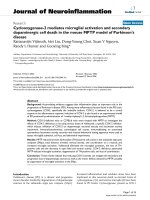
3.2.2. Rule-based agent
The agent has a set of rules written in a very primitive no-
tation at a more reasonable level of abstraction. It is useful
to distinguish three categories of rules: those describing how
the agent reacts to some events, those interconnecting struc-
tural dimensions, and those interconnecting functional di-
mensions (each dimension describes variation in one archi-
tectural characteristic or design choice). Values along a di-
mension correspond to alternative requirements or design
choices. The agent keeps track of three different types of
states: the world state, the internal state, and the database
knowledge. The agent also exhibits two different types of be-
haviors: internal behaviors and external behaviors. The world
state reflects the agent’s conception of the current state of the
architecture and its environment via its sensors. The world
state is updated as a result of interpreted sensory informa-
tion. The internal state stores the agent’s internal variables.
The database knowledge defines the flexible agent rules and
is accessible only to internal behaviors. The internal behav-
iors update the agent’s internal state based on its current in-
ternal state, the world state, and the database knowledge. The
external behaviors of the agent refer to the world and internal
states, and select the actions. The actions affect the architec-
ture, thus altering the agent’s future precepts and predicted
world states. External behaviors consider only the world and
internal states, without direct access to the database knowl-
edge.
In the case of multiagents, the architecture includes a
mechanism providing a basis for orchestrating coordination,
which ensures correctness and consistency in the architecture
at run time, and ensures that agents will have the ability to
communicate, analyze, and generally reason about the mod-
ification.
The behavior of an agent is expressed in terms of rules
grouped together in the behavior units. Each behavior unit
is associated with a specific triggering event type. The re-
ceipt of an individual event of this type a ctivates the behav-
ior described in this behavior unit. The event is defined by
name and by number of parameters. A rule belongs to ex-
actly one behavior unit and a behavior unit belongs to exactly
one class; therefore, the dynamic behavior of each object class
modification is modeled as a collection of rules grouped to-
gether in behavior units specified for that class and triggered
by specific events.
3.2.3. Agent knowledge
The agent may capture different kinds of knowledge to eval-
uate and manage the changes in the architecture. All this
knowledge is part of the database knowledge. In the exam-
ple of a newly added component, the introduction of this
new component type is straightforward, as it can usually be
wrapped by existing behaviors a nd new behaviors. The agent
focuses only on that part of the architecture which is subject
to dynamic reconfiguration.
First, the agent determines the directly related required
properties P
i
involving the new component, then it
(i) finds all properties P
d
related to P
i
and their affected
design;
(ii) determines all inconsistencies needing to be revisited
in the context of P
i
and/or P
d
properties;
(iii) determines any inconsistency in the newly added com-
ponents;
(iv) produces the set of components/connectors and rele-
vant properties requiring reevaluation.
4. EXAMPLES
The first example is a Petri net modeling of a static MMDA,
including a new generic multiagent Petri-net-modeled archi-
tecture. The second shows how to dynamically reconfigure
the dialog architecture when new features are added.
4.1. Example of specification by Petri net modeling
Small, augmented finite-state machines like ATNs have been
used in the multimodal presentation system [44]. These net-
works easily conceptualize the communication syntax be-
tween input and/or output media streams. However, they
have limitations when important constraints such as tempo-
ral information and stochastic behaviors need to be modeled
in fusion protocols. Timed stochastic CPNs offer a more suit-
able pattern [5, 6, 7] to the design of such constraints in mul-
timodal dialog.
For modeling purposes, each input modality is assimi-
lated into a thread where signal fragments flow. Multimodal
inputs are parallel threads corresponding to a changing en-
vironment describing different internal states of the system.
MASs are also multithreaded: each agent has control of one
or several threads. Intelligent agents observe the states of one
or several of the threads for which they a re designed. Then,
the agents execute actions modifying the environment. In
the following, it is assumed that the CPN design toolkit [7]
and its semantics are known. While a description of CPN
modeling is given in Section 4.1.2,wefirstbrieflypresent,in
Section 4.1.1, the augmented transition net principle and its
inadequacies relative to CPN modeling.
4.1.1. Augmented transition net modeling
The principle of ATNs is depicted in Figure 4.
For ATN modeling purposes, a system can change its cur-
rent state when actions are executed under certain condi-
tions. Actions and conditions are associated with arcs, while
Dynamic Reconfiguration of Multimodal Generic Architectures 1695
Node 1
State 1
Transition arc
Condition and action
Node 2
State 2
Figure 4: Principle of ATN.
nodes model states. Each node is linked to another (or to the
same) node by an arc. Like CPN, ATN can b e recursive. In
this case, some transition arcs are traversed only if another
subordinate network is also traversed until one of its end
nodes is reached.
Actually, the evolution of a system depends on conditions
related to changing external data which cannot be modeled
by the ATN.
Achilles’ heel of ATN consists in the absence of a for-
mal associated modeling language for specifying the actions.
This leads to the absence of symbols with associated values to
model event attributes. In contrast, the CPN metalanguage
(CPN ML) [7] is used to perform these specifications.
ATN could therefore be a good tool for modeling the
dialog interactions employed in the multimodal fusion as a
contextual grammatical syntax (see example in Figure 5). In
this case, the management of these interactions is always ex-
ternally performed by the functional kernel of the applica-
tion (code in C++, etc.). Consequently, some variables lost
in the code indicate the different states of the system, lead-
ing to difficulties for each new dialog modification or ar-
chitectural change. The multimodal interactions need both
language (speech language, hand language, written language,
etc.) and action (pointing with eye gaze, touching on tactile
screen, clicking, etc.) modalities in a single interface combin-
ing both anthropomorphic and physical model interactions.
Because of its ML, CPN is more suitable for such modeling.
4.1.2. Colored Petri net modeling
4.1.2.1. Definition
The Petri network is a diagr am flow of interconnected places
or locations (represented by ellipses) and transitions (repre-
sented by boxes). A place or location represents a state and a
transition represents an action. Labeled arcs connect places
to transitions. The CPN is managed by a set of rules (condi-
tions and coded expressions). The rules determine when an
activity can occur and specify how its occurrence changes the
state of the places by changing their colored marks (while the
marks move from place to place). A dynamic paradigm like
CPN includes the representation of actual data with clearly
defined types and values. The presence of data is the fun-
damental difference between dynamic and static modeling
paradigms. In CPN, each mark is a symbol which can repre-
sent all the data ty pes generally available in a computer lan-
guage: integer, real, string, Boolean, list, tuple, record, and so
on. These types are called colorsets. Thus, a CPN is a graph-
ical structure linked to computer language statements. The
design CPN toolkit [7] provides this graphical software envi-
ronment within a programming language (CPN ML) to de-
sign and run a CPN.
4.1.2.2. Modeling a multiagent system with CPN
In such a system, each piece of existing information is as-
signed to a location. These locations contain information
about the system state at a given time and this information
can change at any time. This MAS is called “distributed” in
terms of (see [45])
(i) functional distribution, meaning a separation of re-
sponsibilities in which different tasks in the system are
assigned to certain agents;
(ii) spatial distribution, meaning that the system contains
multiple places or locations (which can be real or vir-
tual).
A virtual location is an imaginary location which already
contains observable information or information can be
placed in it, but there is no assumption of physical infor-
mation linked to it. The set of colored marks in all places
(locations) before an occurrence of the CPN is equivalent to
an observation sequence of an MAS. For the MMDA case,
each mark is a symbol w hich could represent signal frag-
ments (pronounced words, mouse clicks, hand gestures, fa-
cial attitudes, lip movements, etc.), serialized or associated
fragments (comprehensive sentences or commands), or sim-
ply a variable.
A transition can model an agent which generates observ-
able values. Multiple agents can observe a location. The ob-
servation function of an agent is simply modeled by input
arc inscriptions and also by the conditions in each transi-
tion guard (symbolized by [conditions] under a transition).
These functions represent facet A (Figure 6) of agents. Input
arc inscriptions specify data which must exist for an activ-
ity to occur. When a transition is fired (an activity occurs),
a mark is removed from the input places and the activity
can modify the data associated with the marks (or its col-
ors), thereby changing the state of the system (by adding a
mark in at least one output place). If there are colorset mod-
ifications to perform, they are executed by a program asso-
ciated with the transition (and specified by the output arc
label). The progra m is written in CPN ML inside a dashed-
line box (not connected to an arc and close to the transition
concerned). The symbol c specifies [7] that a code is attached
to the transition, as shown in Figure 7. Therefore, each agent
generates data for at least one output location and observes
at least one input location.
If no code is associated with the transition, output arc
inscriptions specify data which will be produced if an activ-
ity occurs. The action func tions of the agent are modeled by
the transition activities and constitute facet E of the agent
(Figure 6).
Hierarchy is another important property of CPN model-
ing. T he symbol HS in a transition means [7] that this is a
hierarchical substitution transition (Figure 7). It is replaced
by another subordinate CPN. Therefore, the input (symbols
[7]PIn)andoutput(symbols[7] P Out) ports of the subor-
dinate CPN also correspond to the subordinate architecture
ports in the hierarchy. As shown in Figure 7 , each transition
and each place is identified by its name (written on it). The
1696 EURASIP Journal on Applied Signal Processing
N1 N2 N3 N4 N5 N6 N7
War ning message
“copy” Msg1 “that”//click
Msg3
Msg2 “past”//click Msg4
War ning message
Figure 5: Example of modeling semantic speech and mouse-clicking an interaction message: (“copy” + (“that”//click) + (“paste”//click)).
Symbols + and // stand for serial and concurrent messages in time. All output arcs are labeled with messages presented in output modalities,
while input ones correspond to user actions. The warning message is used to inform, ask, or warn the user when he stops interacting with
the system. (Msg: output message of the system, N: node representing a state of the system.)
Facet O: organization
Facet E: perception and action
Agent
Facet A: reasoning
Mental state
Facet I: interaction
Location 1 Location 2 Location 3 Location 4 Location 5
Location 6
Location 7
Environment Other agent
Figure 6: AEIO facets within an agent. The locations represent states, resources, or threads containing data. An output arrow from a location
to an agent gives an observation of the data, while an input arrow leads to generation of data.
symbol FG in identical places indicates that the places are
“global fusion” places [7]. These identical places are simply
a unique resource (or location) shared over the net by a sim-
ple graphical artifact: the representation of the place and its
elements is replicated with the symbol FG. All these framed
symbols—P In, P Out, HS, FG, and c—are provided and im-
posed by the syntax of the visual programming toolkit of de-
sign CPN [7].
To summarize, modeling an MAS can be based on four
dimensions (Figure 6), which are agent (A), environment
(E), interaction (I), and organization (O).
(i) Facet A indicates all the internal reasoning functional-
ities of the agent.
(ii) Facet E gathers the functionalities related to the capac-
ities of perception and action of the agent in the envi-
ronment.
(iii) Facet I gathers the functionalities of interaction of
the agent with the other agents (interpretation of the
primitives of the communication language, manage-
ment of the interaction, and the conversation proto-
cols). The actual structure of the CPN, where each
transition can model a global agent decomposed in
components distributed in a subordinate CPN (within
its initial values of variables and its procedures), mod-
els this facet.
(iv) Facet O can be the most difficult to obtain with CPN.
It concerns the functions and the representations re-
lated to the capacities of structuring and managing the
relations between the agents to make dynamic archi-
tectural changes.
Sequential operation is not typical of real systems. Systems
performing many operations and/or dealing with many en-
tities usually do more than one thing at a time. Activities
happening at the same time are called concurrent activi-
ties. A system containing such activities is called a concur-
rent system. CPN easily models this concept of parallel pro-
cesses.
In order to take time into account, CPN is timed and pro-
vides a way to represent and manipulate time by a simple
methodology based on four characteristics.
(1) A mark in a place can have a number associated with
it, called a time stamp. Such a timed mark has its timed
colorset.
(2) The simulator contains a counter called the clock.The
clock is just a number (integer or real number) the cur-
rent value of which is the current time.
(3) A timed mark is not available for any purpose whatso-
ever, unless the clock time is greater than or equal to
the mark’s time stamp.
Dynamic Reconfiguration of Multimodal Generic Architectures 1697
The transition named ParallelFusionAgent models the fusion agent in an
MMDA. The symbol HS means that this agent is decomposed hierarchically
into subagents. Each new subagent can be decomposed into other components.
The symbol HS means that the transition
is a substitution for a whole new net
structure named Mediafusion.
The output arc is labeled with the colorset
of the mark produced when the transition
is fired (firing correponds to agent activity).
Attribute1
Attribute2
Attribute3
InputThread1
InputThread2
OutputThread
(Fragment 1,
property 1 1,
property 1 2, )
(F1, pi1 1, )
(Fragment 2,
property 2 1,
property 2 2, )
(F2, pi2 1, )
(Fragment 3, property 3 1,
property 3 2, )
@+nextTime
FG FusionedMedia
Input (
·)
Output (nextTime)
Action
ParallelFusionAgent
HS Mediafusion
c
[(ArrivalTime1 − ArrivalTime2)
< fusionTime]
This expression,
at the bottom left
of the place, is
an initial chosen
value of the mark(s).
The input arc in a transition
is labeled with the colorset
ofthemarkthatmustexist
in the input place for an
activity occurrence.
Expressions between brackets
define conditions on the values
(associated to the colored
marks) that must be true
for an activity to occur.
With the input arc labels, they
constitute the observation
sequence of the agent.
This output place is a global fusion
placebecauseoftheFGsymbol.A
fusion place is a place that has been
equated with one or more other
places so that the fused places
act as a single place with a single
marking. (Do not confuse this with
the fusion process in MMDA
performed by the whole network.)
FusionedMedia is the name of the
fusion place and
OutputThreadthenameoftheplacein
this locality of the network.
Themarksintheplacearetypedsymbols.
Thetypeorcoloriswrittenattheupper
right of the place and defined in a global
declaration page. Here the colorset name is
Attribute2
The symbol c in the transition means that a code is
linked to the transition activity. The code performs
modifications on the colorset of the output mark.
The code can also generate a temporal value when
the new mark enters the output place. The code is
written in the dashed-line box.
A place models the
state of a thread (in the
system) at a given time.
Thenameofthisplace
is InputThread2.
Explanation
Figure 7: CPN modeling principles of an agent in MMDA.
(4) When there are no enabled transitions (but there
would be if the clock had a greater value), the simu-
lator alters the clock incrementally by the minimum
amount necessary to enable at least one transition.
These four characteristics give simulated time the dimension
that has exactly the properties needed to model delayed activ-
ities. Figure 7 shows how the transition activity can generate
an output-delayed mark. This mark can reach the place Out-
putThread only after a time (equal to nextTime). The value of
nextTime is calculated by the code associated with the transi-
tion. With all these possibilities, CPN provides an extremely
effective dynamic paradigm for modeling an MAS like the
multimedia multimodal fusion engine.
4.1.2.3. The generic CPN-modeled MMDA chosen
The generic multiagent architecture chosen for the multi-
media multimodal fusion engine within CPN modeling ap-
pears in Figure 8. It is an intermediary one between the late
and early fusion architectures depicted in Figure 2.Themain
1698 EURASIP Journal on Applied Signal Processing
Ra Ge of Fr 1
LA 1
Td 1
Modality 1
Sublevel 1
of LA 1
Sublevel n
of LA 1
Instance 1
of distributed PCA
···
···
···
···
Ra Ge of Fr 2
LA 2
Td 2
Modality 2
Sublevel 1
of LA 2
Sublevel n
of LA 2
Instance 2
of distributed PCA
Ra Ge of Fr n
LA n
Td n
Modality n
Sublevel 1
of LA n
Sublevel n
of LA n
Instance n
of distributed PCA
Output Td of fused messages
Figure 8: Generic multiagent scaled architecture of the fusion engine for CPN modeling purposes (A: agent, C: control, Fr: fragments of
signal, Ge: generator, L: language, P: parallel, Ra: random, and Td: thread). The arrows indicate the information and data flows.
features appearing in the proposed generic CPN-modeled ar-
chitecture are summarized in four points.
(i) Distributed architecture. CPN modeling offers the pos-
sibility of distributing PCA over the architecture, as
shown in Figure 8. Each instance of the PCA has its
facets of action, perception, and interaction, depend-
ing on its contextual position in the network.
(ii) Scalable architecture. The architecture has the ability to
sustain a growing load when new modalities are added.
The possibility of decomposing each LA into sublevels
leads to a model which can assist in code generation in
a computer language used in the final implementation
of the system (hierarchy, heritage, etc.) and also gives
the option of reducing the perception mechanisms of
the agents and of spreading them out over the entire
architecture.
(iii) Parallel architecture. Parallelism provides the possibil-
ity of running the application with each LA processed
in a separate parallel hardware. It is also possible to
easily activate or inhibit an LA (in the case of dynamic
architectural reconfiguration) without perturbing the
global running of the application.
(iv) Pipelined architecture. with several input and internal
data streams and one output data stream, it becomes
easy to test and follow the evolution of this multimedia
multimodal architecture with a view to error avoid-
ance. Instances of PCA can handle the diagnostics of
the architecture to prevent system-centered errors, as
shown in the next section.
4.1.2.4. Error avoidance in the proposed
CPN-modeled architecture
Error avoidance can be considered from a user-centered and
a system-centered point of view.
User-centered error avoidance
(i) The user will opt for the input mode that he or she
considers will produce fewer errors for a particular lex-
ical content when the user has a choice between two
equivalent modalities (for example, switching from
speech to pen strokes to communicate a last name).
(ii) The interactive multimodal user language is simpli-
fied. This leads to a decreasing complexity of natural
language processing, thereby reducing recognition er-
rors.
(iii) The user has a natural tendency to switch modes after
a system recognition error, which will lead to fewer er-
rors.
System-centered error avoidance
(i) Within a parallel, distributed, pipelined CPN-modeled
architecture such as this, it is easy to manage errors at
different sublevels of the fusion process. Each signal
(or fragment of signal) thread could be checked. The
error checking can be performed directly by the dis-
tributed PCA or by another agent doubling up the dis-
tributed PCA. Under contextual, temporal, syntactical,
and semantic conditions, this agent purges the thread
from signals (or fragments of signal) which do not cor-
respond to a monomodal action or a multimodal com-
mand. Its complexity could be equal to or beyond the
complexity of the PCA. This agent is also responsible
for warning the user when a fusion or a command is
aborted and/or when the system does not recognize
the user’s messages.
(ii) With the proposed parallel architecture, it is also possi-
ble to use two semantically rich input modes, support-
ing a mutual reduction in ambiguity of signals [21].
For example, in speech recognition associated with a
Dynamic Reconfiguration of Multimodal Generic Architectures 1699
Recognized Word Td
PIn
Word xAt tr ibu te
(Word,(m,ArrivalTimeW,Fm),wtype)
(Word, (m, ArrivalTimeW, Fm),
wtype)
Gr Co
[wtype <> 6 and also wtype <> 7]
Word xAt tr ibu te
Word T d
POut
ClickxAttribute
Click Td
FG ClicksWait
(ClickEvent,
(n, ArrivalTimeC, Fn))
Int
Next F Number
FG NextEventN
(ClickEvent,
(n, ArrivalTimeC, Fn))
p+1
p
SFCo
[abs(ArrivalTimeC − ArrivalTimeW) < abs(1
∗
ProxyTime) and also abs(n−m) < 100]
Next Ev Number
FG NextEventN
Next F Number
FG NextFuN
Fp
p
p+1
p
p+1
SFCo SFCo
(Word, (m,
ArrivalTimeW, Fm),
wtype)
[abs(ArrivalTimeC
− ArrivalTimeW)
< ProxyTime) and also
abs(n−m)< 100]
1’(Word1, (m1, ArrivalTime
W1, Fm1), wtype1) ++
1’(Word2, (m2, ArrivalTime
W2, Fm2), wtype2)
(Fused, (n, m), (p, intTime(·)), (Fp, wt))
Int
Next F Number
FG NextFuSN
Fp
FusedxAttribute
Td FusionedMedia
FG FusionedMedia
(Fused, (n, m), (p, intTime(·)), (Fp, wt))
(Word, (m, ArrivalTimeW), Fm), wtype)
Gr Co
[wtype <> 6]
(Word, (m, ArrivalTimeW, Fm),
wtype)
WordxAttribute
Word T d
(Word, (m, ArrivalTimeW, Fm),
wtype)
1’(Word1, (m1, ArrivalTimeW1,
Fm1), wtype1) ++
1’(Word2, (m2, ArrivalTime2,
Fm2), wtype2)
(ClickEvent,
(n, ArrivalTimeC, Fn))
ClickxAttribute
Click Td
FG ClicksWait
Sn G A
Sn G A
[(wtype1 + wtype2)<> 7
and also
((wtype1 + wtype2) <> 12
and also ((wtype 1 <> 7
(Word, (m1 + m2, imax (ArrivalTimeW1,
ArrivalTimeW2), Fm1 + Fm 2 + 1),
wtype1 + wtype2)
WordxAttribute
Td Sn
Figure 9: Sublevel of the bimodal fusion dialog: the functions used, intTime(·) and imax(·), return the current time and maximum integer
value, respectively (A: agent, Co: component, F: fusion, G: generation, Gr: grammar, L: language, S: semantic, Sn: sentence, and Td: thread).
pen s troke or lip movement recognition device, each
input mode should have a complementary mode in
the architecture. Also, each of the two complementary
modes has to provide duplicated functionality in or-
der to offer the user two equivalent ways to achieve
his or her goals. If the user proceeds with the two
modes in parallel, this could lead to an error avoid-
ance of between 19% and 40% in comparison with
the monomodal recognition system [21]. The p erfor-
mance improvement is the direct result of the reduc-
tion in ambiguity between signals that can occur in
parallel threads because of the fact that each scaled
LA provides a context for interpreting the other LAs
during integration. The time of integr ation (temporal
window in which the system waits for a signal equiv-
alent to the one that has already arrived but has not
been recognized with certainty) is an important crite-
rion. The contextual information is used by the dis-
tributed PCA to confirm to the user that a command
has been executed. This confirmation is sent to an out-
put modality only if the agent needs user corrobora-
tion to make its prognostication. The system is able to
decide by itself under criteria associated with scenar-
ios (decision trees) where probability, grammar, and
semantics play an important role.
The structure of the proposed CPN-modeled architecture is
very suitable for such system-centered error avoidance.
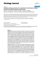
4.1.3. Example of an engine fusion modeled by CPN
A typical example of a distributed architecture for fusion, us-
ing the paradigm in Figure 8, is presented in Figures 9 and
10. The “copy and paste” fusion engine architecture chosen
involves a high-level LA, for speech modality, linked, by a dis-
tributed PCA, to a rudimentary mouse-clicking LA (thread
of clicks). The PCA performs the semantic fusion between
speech and mouse-clicking via two levels (Figures 9 and 10).
Tables 2 and 3 give the vocabulary, used by the speech LA,
and the basic corresponding grammar. Each word has a label
which is used in the CPN design.
In the following, a few regular symbolic expressions are
used to represent semantic elements. These expressions use
the arrow operator for sequential concatenation in the time
domain. For the chosen example, in the semantic expression
(word 1
−→ word 2),
word 1 is simply followed by (or contiguous to) word 2. In
Table 3 , the codes (last column) are obtained simply by sum-
ming the word labels of each semantic code. The obtained
codes give information used by the speech LA for serial con-
structions of sentences in the network.
1700 EURASIP Journal on Applied Signal Processing
Mouse Ev
ME
me
me me@+NextClick
Click Ra Ge
c
Fn
Int
Fnumber
click
0
n
n+1
Input(·);
Output(next click);
Action
Explaw(1.0/(! click arrival));
Int
Next Ev Number
FG NextEventN
1
p+1
p
m
m+1
Word R a Ge
c
we@+Nextwordwe
we
Word Ev
WE
Int
Word t ype
0
wt
Fm
Int
FNumber
Word
0
Input(·);
Output(NextWord);
Action
Explaw(1.0/(! WordArrival));
(Word, (m, intTime(·), Fm), wt)
SFCo
WordxAttribute
Wait
Recognition Td
(Word,(m,ArrivalTimeW,Fm),wt)
Recognition A
c
Input(·);
Output(wtype);
Action
10
∗
rint(1,7);
(Word, (m, intTime (·), Fm), wtype div 10)@+ wtype
[abs(ArrivalTimeC −
ArrivalTimeW)
< abs(ProxyTime)
Fp
Int
Next F Number
FG Next F N
1
(Word, (m,
ArrivalTimeW,
Fm), wtype)
(ClickEvent,
(n, ArrivalTimeC,
Fn))
(Word, (m,
ArrivalTimeW, Fm),
wtype)
(Click Ev,
(n, intTime (·),
Fn))
WordxAttribute
Recognized Word
Td
(Word, (m, ArrivalTimeW, Fm), wtype)
LA
HS SentenceGeneration
(Word, (m, inttime(·), Fm), wtype)
(Fused, (n, m),
(p, intTime(·)),
(Fp, wt))
ClickxAttribute
Click Td
FG Clicks wait
FusedxAttribute
Td FusionedMedia
FG FusionedMedia
(Fused, (n, m2),
(p, ArrivalTimeWp),
(Fp, wt))
Wordxatt rib ute
Word Td
(Word, (m, ArrivalTimeW,
Fm), wtype)
(Word3, (m3,
ArrivalTimeW3,
Fm3), wtype3)
Cancel Word A
(Fused, (m3, m),
(p, intTime (
·)),
(Fm3, wt ype3))
[abs(ArrivalTimeW3 −
ArrivalTimeW)
< abs(ProxyTime div 25)
and also wtype
= 6andalso
abs(m3 − m) < 10]
Fusedxattribute
Td Canceled
Word
Fusedxattribute
Td Canceled
Command
(Fused, (n, m2),
(p, intTime(
·)),
(Fp, wt))
Cancel Command A
[abs(ArrivalTimeWp −
ArrivalTimeW)
< abs(ProxyTime div 25)
and also wtype
= 6andalso
abs (n − m) < 10]
Figure 10: Bimodal fusion dialog. The functions intTime(·), rint(·), and Explaw(·) return current time, discrete uniform, and exponential
distribution, respectively (A: agent, Co: component, Ev: event, F: fusion, Ge: generator, L: language, Ra: random, S: semantic, and Td:
thread).
Dynamic Reconfiguration of Multimodal Generic Architectures 1701
Table 2: Vocabulary.
Word Word l abel Word Word label
Open 1 Paste 5
Close 2 Cancel 6
Delete 3 That 7
Copy 4
The word “cancel” is a command which automatically
cancels the last action among the authorized sentences.
Therefore, if the user says one of the words labeled in the set
{1, 2,3, 4, 5} just after “cancel,” the time proximity between
the two words is the decision criterion for suppressing the
second word or taking it as a next command. For the pro-
posed architecture, both scenarios are processed. The multi-
modal dialog gives, for each sentence, a set of possible redun-
dant fusions. The symbol // models these concurrent associ-
ations in regular expressions.
For example, depending upon temporal information, the
first command given in Tabl e 3 is an element of the following
semantic fusion set:
(click −→ open −→ that); (open −→ click);
(click −→ open); (click//open);
(click//open) −→ that
;
(click//
open −→ that)
.
This semantic set includes the grammatical sentences corre-
sponding to the command “open object.” Words, temporally
isolated and labeled in the set {1, 2, 3, 4, 7}, are not consid-
ered by the PCA. The remaining fusion entities, like ((close
→ open)//click), (click//(delete → open)), and so forth, or
isolated clicks, are also ignored by the system. Thus, some er-
rors made by the user are avoided by the model. The whole
sets constitute the semantic knowledge.
The associated CPN in Figures 9 and 10 uses two ran-
dom generators to design the arrival time of the input media
events (mouse clicks and words). The random (Ra) genera-
tors (Ge) are drawn at the top of Figure 9 with dashed non-
bold lines, and both are modeled with the transitions named
“Ra Ge Click” and “Ra Ge Word.” The interarrival time be-
tween two pronounced words, as well as the time between
two consecutive “clicks,” is exponentially distributed. Events
(like words and clicks) are generated or arrive at two dif-
ferent threads (the places “Click Td” and “Word Td”). The
time between two click (resp., word) arrivals has a mean =
ClickArrival (resp., = WordArrival). The interarrival time be-
tween two click (resp., word) events has an exponential dis-
tribution with parameter r = 1/ClickArrival (resp., 1/Wor-
dArrival).
The interarrival time follows an exponential law for the
words and also for the clicks. If the time proximity between a
word event and a click event is b elow the variable ProxyTime
and if these two events verify the grammatical and semantic
conditions (given between brackets under the semantic fu-
sion component modeled by the transition named “SFCo”),
then these two events are fused into one command.
The transitions drawn with bold dashed lines model the
PCA components distributed over the network. Transitions,
with bold lines, model the speech LA components in Figures
9 and 10. The mouse click LA is reduced to a simple thread
(Td), “Click Td”, where symbols flow. The transition “Recog-
nition A” (Figure 9) assigns a random label “wtype” to each
word present in the place “Recognized Word Td.” This ran-
dom assignment does not model a real flowing speech be-
cause the automatic modeling of user speech is outside the
scopeofthispaper.However,itissufficient to model times
of recognition.
One of the main focuses in this paper is how to use timed
semantic knowledge to achieve a multimodal fusion. There-
fore, the network in Figure 9 describes interactions at a sub-
level of the network in Figure 10. More precisely, Figure 9
models the interactions of the speech LA (Figure 10)gram-
matical components (Gr Co) and the sentence generation
agent (Sn G A in Figure 9). It also models different instances
of the SFCo of the PCA distributed on the hierarchical (here,
two-level) network architecture.
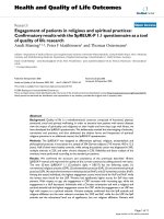
4.1.4. Simulation results
Figures 11a and 11b show the simulation results for WordAr-
rival = ClickAr rival = 5000 milliseconds and ProxyTime =
10000 milliseconds.
Figure 11a presents the number of fusions achieved in the
time period (or the number of marks in the “FusionedMe-
dia” place of the CPN). In the same way, a command can be
canceled if the user says the word “cancel” just after a com-
mand has been carried out (the proximity time between the
two events, the command and the word “cancel,” is chosen
below (ProxyTime/25)). Figure 11b shows the resulting can-
celed commands in the time period (or the number of marks
arrived at in the place “Canceled Command”). Figures 11a
and 11b are obtained after simulation of the network (Fig-
ures 9 and 10).
The results in Figure 11 quantify perceivable behavior
of the architecture for random arrival time of inputs. This
behavior depends on a temporal proximity criterion. These
results could vary according to the value of the “Proxy-
Time.” Adjustment of this value should take into account the
mean temporal behavior of users. This is done by a perti-
nent fine tuning of the random generators with the function
Explaw(·). It should also consider processing time, which
is modeled by the value “wtype” returned by the transition
program “Recognition System.” The example of this section
shows that the fusion engine works and performs semantic
fusion (by combining the results of commands to derive new
results) as well as syntactic ones (by combining data to obtain
a complete command).
4.2. Dynamic reconfiguration example
In this section, we describe, in brief, an application which is
used to add new media to an MMDA while the application
is running. The system is briefly presented here. In the ini-
tial architecture (Figure 12a), for simplicity, each con j (con-
nection j between two components via a connector) corre-
sponds to the representation in Figure 12b. The initial system
1702 EURASIP Journal on Applied Signal Processing
Table 3: Grammar of authorized sentences (the last two columns are codes used in the CPN).
Set of sentences Command meaning Set of corresponding semantic codes Set of corresponding codes
{(open → that); (open)} Open object {(1 → 7); (1)}{(8); (1)}
{(close → that); (close)} Close object {(2 → 7); (2)}{(9); (2)}
{
(delete → that); (delete)} Delete object {(3 → 7); (3)}{(10); (3)}
{(paste)} Paste last copied object {(5)}{(5)}
{(copy → that); (copy)} Copy object {(4 → 7); (4)}{(11); (4)}
{(cancel)} Cancel last command {(6)}{(6)}
0 500 1000 1500 2000 2500
Time (×10 ms)
0
2
4
6
8
10
12
14
Number of fusions
(a)
0 500 1000 1500 2000 2500
Time (×10 ms)
0
1
2
3
4
5
6
Number of cancels
(b)
Figure 11: (a) Achieved semantic fusions. (b) Canceled command.
is composed of two media (see Section 4.1). The fusion is
performed by a PCA. According to the application require-
ments, efficiency in time behavior is more important than
the other quality attributes. In order to improve this quality
attribute, the agents must perform the reconfiguration atom-
ically and g radually. The adaptation must be conducted in a
safe manner to ensure the integrity of the global architecture
during running time. On reception of the event (new modal-
ity used), the agent will state the following strategy, w hich
consists of applying some rule operations. The architectural
reconfiguration agent
(i) adds a new data collector and PCA components (for
fusion purposes) to the application;
(ii) creates a new modality database;
(iii) makes decisions on deleting each old connection con
j by testing whether or not it is passive (there are no
transit data between the two components related to
this connection).
If a connection is passive, the agent deletes it and activates
the new one just created then transfers the state of the corre-
sponding connector to the new connector.
The agent does this in real time until the desired new
application (Figure 12c) replaces the initial one. The new
modality is a media device called the eye-gaze response inter-
face computer aid. It is specially adapted with imaging hard-
ware and software. The user interface accepts input directly
from the human eye. Menu options are displayed at different
positions on the computer monitor.
By simply looking at a given position, the corresponding
menu option is invoked. In this way, a disabled user can in-
teract with the computer, run communications and other ap-
plications software, and manage peripheral devices. An agent
will be associated with this device to control its hardware (de-
vice management agent (DMA)). Other agents manage soft-
ware configuration and also implement the eye-gaze position
detection algorithm.
5. THE NOVELTY OF OUR APPROACH
The novelty of our approach is demonstrated by the pro-
posed multiagent paradigms of the generic CPN-modeled
MMDA, and also with the dynamic reconfiguration of the
MMDA at the architectural level. To support the novel as-
pect of the approach, this section describes the three main
characteristics of the proposed architecture through a mul-
timodal interface software application called Interact Soft-
ware 1.0 (IAS). IAS is dedicated to use by disabled individ-
uals (particularly those who are paralyzed, like hemiplegics,
quadriplegics, etc.), and is based on a fusion engine archi-
tecture modeled with a design CPN, a s shown in the previ-
ous sections. The developed application offers a Web browser
interface running on the MS Windows 9x/ME/NT/2000 XP
OS platform for portability reasons and using multithreading
and other advantages of this 32-bit environment. Eye tracker
equipment is used to detect gaze position on a screen mon-
itor [46 ]. Calibration of the eye-gaze material for each user
is necessary to achieve accurate gaze position tracking. The
Dynamic Reconfiguration of Multimodal Generic Architectures 1703
Mod 1
con 3
con 1
PCA
DB
Mod 1
con 4
con 2
Provided port Provided role
(a)
Component 1
port j role j role j port j
Component 2
con j
Connector j
Required port Required role
(b)
Agent
Perception
New con 1
New con 2
D
C
New con 3
New con 4
New con 5
New con 6
New con 7
New con 8
New con 9
New con 10
New con 11
Mod 1
Mod 2
Mod 3
New PCA
PCA
con 1con 2
DB
New DB
Provided port Provided role Required port Required role
(c)
Figure 12: (a) The initial architecture. (b) Connection j (con j). (c) The final desired architecture. (Mod: modality, Cl: collector, D: data,
DB: database, P: parallel, C: control, A: agent, and con: connection.)
calibration needs to be performed only once, and is saved
in a database for each user. The calibration data are there-
fore set for individual users who are identified by the IAS via
a password protocol. The eye-gaze position information on
the screen is used in real time to move the mouse pointer.
The software used for voice recognition and vocal synthe-
sis is Microsoft Speech API: SDK4.0. A set of vocal com-
mands (a word or a word combination) is predefined for this
purpose. In IAS developed with C++, the input modalities
are voice recognition, eye-gaze position detection, a mouse,
and/or a tactile screen. The keyboard can also be used, and
a virtual vocal keyboard and a virtual vocal mouse-clicking
device are also available. The output modalities are voice
synthesis and monitor-screen display. It should be noted
that the screen device is involved in both input and output
modes.
5.1. Flexibility of the architecture
Several characteristics confer flexibility onto the architec-
ture. Each LA has an “interpreter” component which has two
functions:
(i) interpretation of the signals coming from the input de-
vices;
(ii) transformation of these signals into events which can
be understood by the PCA.
With each specialized DMA, there is an interpreter compo-
nent, depending on the nature of the mode. This property
gives the architecture its generic characteristics in terms of
flexibility: the user can change, add, or abandon the modali-
ties while the application is running. This is possible because
each new modality is automatically adapted to the fusion en-
gine. Switching between modalities in the architecture is easy
to do in run-time mode. IAS also gives the user the ability to
configure the fusion time, a nd in fact this is done automat-
ically, either by default after the interface has been used or
directly via the interface.
5.2. Dynamic aspects
The vision of ubiquitous computing, which was introduced
in the early ’90s [47], is now giving rise to extensive research
[48, 49, 50, 51, 52]. While ubiquitous computing could have
been considered to be quite futuristic in those days, the com-
bined effect of advances in the areas of hardware and net-
work technologies and of the universal use of Internet-based
technologies and wireless phones makes it almost a reality.
The vision is now termed “ambient intelligence” or “per-
vasive computing” to emphasize that it does not rely solely
on its ubiquitous nature (i.e., the useful, pleasant, and un-
obtrusive presence of computing devices everywhere), but
also on ubiquitous networking (i.e., access to networks and
computing facilities everywhere) and on intelligent, “aware”
1704 EURASIP Journal on Applied Signal Processing
(a)
(b) (c)
Figure 13: (a) T he intuitive menu of Interact Software. (b) Input modality interface in Interact Software. (c) The Interact navigator: a
user-friendly Web navigator with functionalities adapted to predefined eye gaze and/or voice commands.
interfaces (i.e., the system is perceived as intelligent by peo-
ple who naturally interact with a system which automati-
cally adapts to their preferences). For example, the IAS menu
groups together all the modes (eye gaze, voice, etc.) to access
the tools of the software environment. The IAS can thus be
said to constitute an intelligent and aware interface.
As shown in Figure 13a (from left to right), the user can
select and activate the following tools:
(1) initialize IAS;
(2) load Interact real-time fusion engine analysis and pa-
rameter interface;
(3) load Web Interact navigator;
(4) work in Windows OS;
(5) configure audio device;
(6) calibrate eye gaze;
(7) set time-fusion parameter;
(8) switch on vocal inactivit y gauge.
The vocal inactivity gauge in particular constitutes an exam-
ple of a mbient intelligence. The last button on this menu bar
contains a visual gauge indicating the vocal inactivity of the
user. If there is no input event at all (total inactivity of the
user in a given period of time), a multimodal w arning mes-
sage is presented, and, as a result, a screen saver can be exe-
cuted. The interface is thus attentive to the activity as well as
to the passivity of the user.
When the IAS is reduced to a tray icon system, IAS is
still running and the user can use his or her gaze and voice
to operate Windows OS, and so open and use the classic
Windows application. (Open Media Player and Windows Ex-
plorer, move files, use the virtual keyboard to edit text, etc.)
Of course, an application like Windows Explorer does not
work efficiently with multimodal inputs like eye-gaze and
voice detection. As a remedy for its inadequacies, the Web
navigator of IAS (Figure 13c ), with its set of vocal commands
and large icons (adapted to eye-gaze detection), offers a bet-
ter environment. With all the possibilities it offers, the IAS
Web navigator provides the W3C application with its ubiq-
uitous computing aspect.
Enabling the ambient intelligence vision means provid-
ing consumers with universal and immediate access to avail-
able content and services, together with ways of effectively
exploiting them. This is also true of the proposed interface,
where the user switches from one modality to another in run
time. In terms of the software system’s development aspect,
this means that the actual implementation of our ambient
intelligence application as requested by a user can only be re-
solved at run time according to the user’s specific situation.
This is possible while the architecture for MMDA and its
associated core agent-based middleware are attentive to each
dynamic composition according to the task environment. We
can confirm that the proposed multiagent architecture cor-
roborates W3C MMI activities.
Dynamic Reconfiguration of Multimodal Generic Architectures 1705
5.3. Reliability of the architecture
The quality attributes of the software elegantly manage er-
rors made by the user, offering a user-friendly help envi-
ronment throughout the output modalities (vocal synthesis,
hints, and pop-up messages displayed on-screen). When the
software is executed for the first time, a pop-up window ap-
pears. Eye-gaze and vocal input and output modalities are
activated by default. The user is then able to choose other
available modalities or deactivate any of them (Figure 13b).
After 10 seconds of user inactivity, a vocal signal within a dis-
played password window message initiates the user’s identi-
fication protocol. This identification lets the system load the
calibration settings of the eye-gaze tracker system. If there
is no reaction from the user, IAS vocally confirms that the
eye-gaze and speech modalities are activated with the default
calibration parameters, and a pop-up help window displays
the available help command.
The user can also say “help” anytime and a contextual
help message (related to the mouse cursor position) is dis-
played.
The IAS then continues with the remaining human-
machine communication protocol processes. The applica-
tion never breaks down if a word spoken by the user or a
command is not recognized. An alternative message can al-
ways be displayed or synthesized vocally to avoid system jam-
ming. In terms of error avoidance, the whole application,
within its dynamic architecture, constitutes a robust inter-
face.
6. CONCLUSION
In this paper, new agent-based architectural paradigms
for multimedia multimodal fusion purposes are proposed.
These paradigms lead to new generic structures unifying
applications based on multimedia multimodal dialog. They
also offer developers a framework specifying the various
functionalities used in multimodal software implementation.
In the first phase, the main common requirements and con-
straints needed by multimodal dialogs are set down. Then
the interaction types related to early and late fusions are pre-
sented. After identifying the recurrent generic characteristics
shared by all modalities, each input medium is associated
with a sp ecific language agent (LA). The LAs are intercon-
nected directly or through a distributed parallel control agent
(PCA) to perform the dialog. The architecture of the PCA is
decomposed into intelligent components to make up a mod-
ular structure. These components manage temporal, redun-
dant, and grammatical conflicts. The proposed architectures
are modeled with timed, colored Petri networks and support
both parallel and serial fusions. These architectures do not
change dynamically. In order to introduce real-time changes
to the previous MMDAs, a new agent-based architecture with
the ability to react to events and perform architectural recon-
figuration autonomously is proposed. The efficiency of the
new architecture is detailed through several application ex-
amples, including a multimodal W3C interface for disabled
individuals.
ACKNOWLEDGMENTS
The authors would like to thank the Commission Perma-
nente de Coop
´
eration Franco-Qu
´
eb
´
ecoise 2003–2004, which
is in turn supported by Qu
´
ebec’s Ministry for International
Relations and France’s Ministry for Foreign Affairs (General
Consulate of France in Qu
´
ebec). This project was also finan-
cially supported by the Natural Sciences and Engineering Re-
search Council (NSERC) of Canada.
REFERENCES
[1] R. A. Bolt, “Put-that-there: Voice and gesture at the graphics
interface,” ACM Computer Graphics, vol. 14, no. 3, pp. 262–
270, 1980.
[2] J.L.CrowleyandF.B
´
erard, “Multi-modal tracking of faces for
video communications,” in Proc. IEEE Computer Society Con-
ference on Computer Vision and Pattern Recognition (CVPR
’97), pp. 640–645, IEEE Computer Society, San Juan, Puerto
Rico, June 1997.
[3] Y. Bellik and D. Burger, “Multimodal interfaces: new solu-
tions to the problem of computer accessibility for the blind,”
in Proc. ACM Conference on Human Factors in Computing Sys-
tems (CHI ’94), pp. 267–268, Boston, Mass, USA, April 1994.
[4] D. R. McGee, P. R. Cohen, and L. Wu, “Something from
nothing: Augmenting a paper-based work practice with mul-
timodal interaction,” in Proc. Designing Augmented Reality
Environments Conference (DARE ’00), pp. 71–80, ACM Press,
Elsinore, Denmark, April 2000.
[5] K. Jensen, Coloured Petri Nets. Basic Concepts, Analysis Meth-
ods and Practical Use, Volume 1, Basic Concepts, Monographs
in Theoretical Computer Science. Springer-Verlag, New York,
NY, USA, 2nd corrected edition, 1997.
[6] K. Jensen, Coloured Petri Nets. Basic Concepts, Analysis Meth-
ods and Practical Use, Volume 2, Analysis Methods,Mono-
graphs in Theoretical Computer Science. Springer-Verlag,
New York, NY, USA, 2nd corrected printing, 1997.
[7] K. Jensen, S. Christensen, P. Huber, and H. Holla, Design/CPN
Reference Manual, Department of Computer Science, Univer-
sity of Aarhus, Aarhus, Denmark, 1995.
[8] F. Az
´
emard, Des r
´
ef
´
erences dans le dialogue homme machine
multimodal une approche adapt
´
ee du formalisme des graphes
conceptuels, Ph.D. thesis, University Paul Sabatier, Toulouse,
France, February 1995.
[9] S. Card, J. Mackinlay, and G. Robertson, “The design space
of input devices,” in Proc. ACM Conference on Human Factors
in Computing Systems (CHI ’90), pp. 117–124, Seattle, Wash,
USA, April 1990.
[10] W. Buxton, “Lexical and pragmatic considerations of input
structures,” Computer Graphics, vol. 17, no. 1, pp. 31–37,
1983.
[11] J. Foley, V. Wallace, and P. Chan, “The human factors of
computer graphics interaction techniques,” IEEE Computer
Graphics and Applications, vol. 4, no. 11, pp. 13–48, 1984.
[12] D. Frohlich, “The design space of interfaces, multimedia sys-
tems, interaction and applications,” in Proc. 1st Eurographics
Workshop, pp. 53–69, Stockholm, Sweden, April 1991.
[13] N. Bernsen, Taxonomy of HCI Systems: State of the Art,ES-
PRIT BR GRACE, Deliverable 2.1, 1993.
[14] J. Coutaz and L. Nigay, “Les propri
´
et
´
es CARE dans les inter-
faces multimodales,” in Sixi
`
emes Journ
´
ees sur l’Ing
´
enierie des
Interfaces Homme-Machine (IHM ’94), pp. 7–14, Lille, France,
December 1994.
[15] S. L. Oviatt, “Multimodal signal processing in naturalistic
noisy environments,” in Proc.6thInternationalConferenceon
Spoken Language Processing (ICSLP ’00), B. Yuan, T. Huang,
1706 EURASIP Journal on Applied Signal Processing
and X. Tang, Eds., vol. 2, pp. 696–699, Chinese Friendship
Publishers, Beijing, China, October 2000.
[16] S. L. Oviatt, “Multimodal system processing in mobile envi-
ronments,” in Proc. 13th Annual ACM Symposium on User In-
terface Software Technology (UIST ’00), vol. 2, pp. 21–30, ACM
Press, San Diego, Calif, USA, November 2000.
[17] E. L. Hutchins, J. D. Hollan, and D. A. Norman, “Direct ma-
nipulation interfaces,” in User Centered System Design: New
Perspectives on Human-Computer Interaction,D.A.Norman
and S. W. Draper, Eds., pp. 87–124, Lawrence Erlbaum Asso-
ciates, Hillsdale, NJ, USA, 1986.
[18] S. L. Oviatt, P. R. Cohen, L. Wu, et al., “Designing the user
interface for multimodal speech and pen-based gesture ap-
plications: state-of-the-art systems and future research direc-
tions,” Human Computer Interaction, vol. 15, no. 4, pp. 263–
322, 2000.
[19] C. Bregler, H. Hild, S. Manke, and A. Waibel, “Improving
connected letter recognition by lipreading,” in Proc. IEEE
Int. Conf. Acoustics, Speech, Signal Processing (ICASSP ’93) ,
vol. 1, pp. 557–560, IEEE Press, Minneapolis, Minn, USA,
April 1993.
[20] Projet AMIBE, “Rapport d’activit
´
e, GDR |n
◦
9, GDR-PRC
Communication Homme-Machine,” Tech. Rep., CNRS,
MESR, pp. 59–70, 1994 (French).
[21] S. L. Oviatt, “Mutual disambiguation of recognition errors
in a multimodal architecture,” in Proc. ACM Conference on
Human Factors in Computing Syste ms (CHI ’99), pp. 576–583,
ACM Press, Pittsburgh, Pa, USA, May 1999.
[22] Y. Bellik, Interfaces multimodales: concepts mod
`
eles architec-
tures, Ph.D. thesis, University of Paris XI, Paris, France, 1995.
[23] N. R. Jennings and M. J. Wooldridge, “Applications of intel-
ligent agents,” in Agent Technology: Foundations, Applications,
and Markets, N. R. Jennings and M. Wooldridge, Eds., pp. 3–
28, Springer-Verlag, New York, NY, USA, 1998.
[24] G. Weiss, Multiagent Systems, MIT Press, Cambridge, Mass,
USA, 1999.
[25] S. D. Bird, “Toward a taxonomy of multi-agent systems,” In-
ternat ional Journal of Man-Machine Studies,vol.39,no.4,pp.
689–704, 1993.
[26] A. H. Bond and L. Gasser, Readings in Distributed Artificial
Intelligence, Morgan Kaufmann, San Mateo, Calif, USA, 1988.
[27] T. Ishida, Real-Time Search for Learning Autonomous Agents,
Kluwer Academic, Norwell, Mass, USA, 1997.
[28] H. J. Muller, “Negotiation principles,” in Foundations of Dis-
tributed Artificial Intelligence,G.M.P.O’HareandN.R.Jen-
nings, Eds., pp. 211–230, John Wiley & Sons, New York, NY,
USA, 1996.
[29] P. R. Cohen, H. R. Levesque, and I. Smith, “On team for-
mation,” in Contemporary Action Theory, J. Hintikka and
R. Tuomela, Eds., Synthese, Kluwer Academic, Dordrecht,
Netherland, 1997.
[30] J R. Abrial, The B-Book: Assigning Programs to Meanings,
Cambridge University Press, Cambridge, UK, 1996.
[31] J. Kramer and J. Magee, “The evolving philosophers problem:
dynamic change management,” IEEE Transactions on Software
Engineering, vol. 16, no. 11, pp. 1293–1306, 1990.
[32]P.Oreizy,N.Medvidovic,andR.N.Taylor, “Architecture-
based runtime software evolution,” in Proc. 20th International
Conference on Software Engineering (ICSE ’98), pp. 177–186,
Kyoto, Japan, April 1998.
[33] R. J. Allen, R. Douence, and D. Garlan, “Specifying dynamism
in software architectures,” in Proc. Workshop on Foundations of
Component-Based Software Engineering, Zurich, Switzerland,
September 1997.
[34] R. N. Taylor, N. Medvidovic, K. M. Anderson, et al., “A
component- and message-based architectural style for GUI
software,” IEEE Transactions on Software Engineering, vol. 22,
no. 6, pp. 390–406, 1996.
[35] J. Kramer and J. Magee, “Self organizing software architec-
tures,” in Joint Proceedings of the 2nd International Software
Architecture Workshop (ISAW-2) and International Workshop
on Multiple Perspectives in Software Development (Viewpoints
’96), pp. 35–38, ACM Press, San Francisco, Calif, USA, Octo-
ber 1996.
[36] J. M. Purtilo, “The POLYLITH software bus,” ACM Transac-
tions on Programming Languages and Systems, vol. 16, no. 1,
pp. 151–174, 1994.
[37] M. Barbacci, C. Weinstock, D. Doubleday, M. Gardner, and
R. Lichota, “Durra: a structure description language for de-
veloping distributed applications,” Software Engineering Jour-
nal, vol. 8, no. 2, pp. 83–94, 1993.
[38] T. Bloom and M. Day, “Reconfiguration and module replace-
ment in Argus: theory and practice,” Software Engineering
Journal, vol. 8, no. 2, pp. 102–108, 1993.
[39] J. Magee and J. Kramer, “Dynamic structure in software ar-
chitectures,” in Proc. 4th ACM SIGSOFT Symposium on the
Foundations of Software Enginee ring (FSE ’96), pp. 3–14, ACM
Press, San Francisco, Calif, USA, October 1996.
[40] R. De Nicola, G. Ferrari, and R. Pugliese, “KLAIM: a kernel
language for agents interaction and mobility,” IEEE Trans-
actions on Software Engineering, vol. 24, no. 5, pp. 315–330,
1998.
[41] P. Ciancarini and C. Mascolo, “Software architecture and mo-
bility,” in Proc. 3rd Annual International Workshop on Software
Architecture (ISAW ’98), pp. 21–24, ACM Press, Orlando, Fla,
USA, November 1998.
[42] W. Van Belle and J. Fabry, “Experience in mobile comput-
ing/The Cborg mobile multi-agent system,” in Technology
of Objet-Oriented Languages and Systems, Tools 38, pp. 7–18,
Zurich, Switzerland, March 2001.
[43] A. Ramdane-Cherif and N. Levy, “An approach for dynamic
reconfigurable software architectures,” in Proc. 6th World
Conference on Integrated D esign and Process Technology (IDPT
’02), Pasadena, Calif, USA, June 2002.
[44] S C. Chen and R. L. Kashyap, “Temporal and spatial seman-
tic models for multimedia presentations,” in Proc. Interna-
tional Symposium on Multimedia Information Processing (IS-
MIP ’97), pp. 441–446, Taipei, Taiwan, December 1997.
[45] P. Tabeling, “Multi-level modeling of concurrent and dis-
tributed systems,” in Proc. International Conference on Soft-
ware Engineering Research and Practice (SERP ’02),LasVegas,
Nev, USA, June 2002.
[46] User’s Guide, The eyegaze development system for windows
NT/2000, LC Technologies, May 2003. gaze.
com.
[47] M. Weiser, “Some computer science problems in ubiquitous
computing,” Communications of the ACM,vol.36,no.7,pp.
74–83, 1993.
[48] M. L. Der touzos, “The future of computing,” Scientific Amer-
ican, vol. 281, no. 2, pp. 52–55, 1999.
[49] M. Esler, J. Hightower, T . Anderson, and G. Borriello,
“Next century challenges: data-centric networking for invisi-
ble computing,” in Proc. 5th ACM Conference on Mobile Com-
puting and Networking (MOBICOM ’99), pp. 256–262, Seattle,
Wash, USA, August 1999.
[50] IST Advisory Group (ISTAG), “Scenarios for ambient intelli-
gence in 2010,” Tech. Rep., Information Society Technologies
Advisory Group, 2001, />[51] D. Garlan, D. Siewiorek, A. Smailagic, and P. Steenkiste,
“Project Aura: toward distraction-free pervasive computing,”
IEEE Pervasive Computing, vol. 1, no. 2, pp. 22–31, 2002.
Dynamic Reconfiguration of Multimodal Generic Architectures 1707
[52] D. Milojicic, A. Messer, P. Bernadat, et al., “ψ-pervasive ser-
vices infrastructure,” in Proc. 2nd International Workshop
on Technologies for E-Services (TES ’01), vol. 2193 of Lecture
Notes in Computer Science, pp. 187–200, Rome, Italy, Septem-
ber 2001.
H. Djenidi received his B.S. degree from
the University of Science and Technology
Houari Boumediene, Algiers, Algeria, in
electrical engineering and his M.S. degree in
metrology and systems from Conservatoire
National des Arts et M
´
etiers (CNAM), Paris,
France, respectively, in 1992 and 1994. From
1995 to 2002, he has been a Research As-
sistant for Canal Plus Inc. via CNAM and
for Aircraft Bombardier Inc. via
´
Ecole de
Technologie Sup
´
erieure (ETS), University of Quebec at Mon-
treal, Canada. He was also an Electronic and Software Engineer-
ing Teacher at the Universities of Versailles and Cr
´
eteil, France,
and ETS, Canada. Since 2003, he has been studying for his Ph.D.
at PRISM Laboratory, University of Versailles Saint-Quentin-en-
Yvelines, France, and ETS, Canada. His investigations and field in-
terests include multimodal interactions, multiagent architectures,
and software specifications. Hicham Djenidi is a Student Member
of IEEE.
S. B enarif received his B.S. degree from
the University of Science and Technol-
ogy Houari Boumediene, Algiers, Algeria,
in electrical engineering and his M.S. de-
gree from the University of Versailles Saint-
Quentin-en-Yvelines, France, respectively,
in 2000 and 2002. Since 2003, he has been
studying for his Ph.D. at PRISM Laboratory,
University of Versailles, France. His investi-
gations and field interests include dynamic
architecture, architectural quality attributes, architectural styles,
and design patterns.
A. Ramdane-Cherif received his Ph.D. de-
gree from Pierre and Marie Curie Univer-
sity of Paris in 1998 in neural networks
and AI optimization for robotic applica-
tions. Since 2000, he has been an Associate
Professor at PRISM Laboratory, Univer-
sity of Versailles Saint-Quentin-en-Yvelines,
France. His main current research inter-
ests include software architecture and for-
mal specification, dynamic architecture, ar-
chitectural quality attributes, architectural styles, and design pat-
terns.
C. Tadj is a Professor at
´
Ecole de Technolo-
gie Sup
´
erieure (ETS), University of Quebec,
Montreal, Canada. He received a Ph.D. de-
gree in signal and image processing from
ENST Paris in 1995. He is a Member of the
Laboratory of Integration of Technologies
of Information (LITI) at ETS. His main re-
search interests include automatic recogni-
tion of speech and voice mark, word spot-
ting, HMI, and multimodal and neuronal
systems.
N. Levy is a Professor at the Univer-
sity of Versailles Saint-Quentin-en-Yvelines,
France. She has a Doctorate in Mathemat-
ics from the University of Nancy (1984). She
directs an engineering school, the ISTY, and
is responsible for the SFAL team (Formal
Specification and Software Architecture) of
PRISM, the laboratory of the university as-
sociated with the CNRS. Her main research
interests include formal and semiformal development methods,
style and architectural models formalization, and quality attributes
of software architectures and distributed systems.