Báo cáo hóa học: " A Methodology for Rapid Prototyping Peak-Constrained Least-Squares Bit-Serial Finite Impulse Response Filters in FPGAs" pptx
Bạn đang xem bản rút gọn của tài liệu. Xem và tải ngay bản đầy đủ của tài liệu tại đây (780.58 KB, 10 trang )
EURASIP Journal on Applied Signal Processing 2003:6, 555–564
c
2003 Hindawi Publishing Corporation
A Methodology for Rapid Prototyping Peak-Constrained
Least-Squares Bit-Serial Finite Impulse Response
Filters in FPGAs
Alex Carreira
Department of Electrical and Computer Engineering, University of Calgary, 2500 University Drive N.W.,
Calgary, Alberta, Canada T2N 1N4
Email:
Trevor W. Fox
Department of Electrical and Computer Engineering, University of Calgary, 2500 University Drive N.W.,
Calgary, Alberta, Canada T2N 1N4
Email:
Laurence E. Turner
Department of Electrical and Computer Engineering, University of Calgary, 2500 University Drive N.W.,
Calgary, Alberta, Canada T2N 1N4
Email:
Received 28 February 2002 and in revised form 17 October 2002
Area-efficient peak-constrained least-squares (PCLS) bit-serial finite impulse response (FIR) filter implementations can be rapidly
prototyped in field programmable gate arrays (FPGA) with the methodology presented in this paper. Faster generation of the
FPGA configuration bitstream is possible with a new application-specific mapping and placement method that uses JBits to avoid
conventional general-purpose mapping and placement tools. JBits is a set of Java classes that provide an interface into the Xilinx
Virtex FPGA configuration bitstream, allowing the user to generate new configuration bitstreams. PCLS coefficient generation
allows passband-to-stopband energy ratio (PSR) performance to be traded for a reduction in the filter’s hardware cost without
altering the minimum stopband attenuation. Fixed-point coefficients that meet the frequency response and hardware cost spec-
ifications can be generated with the PCLS method. It is not possible to meet these specifications solely by the quantization of
floating-point coefficients generated in other methods.
Keywords and phrases: placement, mapping, FIR filter, PCLS, bit serial, JBits.
1. INTRODUCTION
Finite duration impulse response (FIR) digital filters are crit-
ical components in a wide spectrum of digital signal pro-
cessing (DSP) operations and systems. Examples include:
decimation, radar, and image processing [1]. Rapid proto-
typing of FIR filters is important in reducing development
time and costs. Previous research efforts have focused on
implementation and system architecture [2, 3, 4] with lit-
tle or no attention paid to methods for rapid prototyp-
ing. Filter performance should not be sacrificed in a rapid
prototyping methodology for FIR filters. A recent design
that can be used to rapidly prototype FIR filters [5]usesa
windowing technique that sacrifices the ability to precisely
control the frequency response performance of the filter
[1].
The FIR filter frequency response performance can be
controlled by the method of peak-constrained least-squares
(PCLS), which allows both the minimum stopband attenu-
ation and the passband-to-stopband energy ratio (PSR) to
be controlled [6]. A method for rapidly prototyping PCLS
bit-serial FIR filters that is able to trade PSR performance
for reduced hardware area in the FPGA without altering the
minimum stopband attenuation is described in this paper.
Fixed-point coefficients that meet the frequency response
and hardware cost specifications can be generated w ith the
PCLS method. It is not possible to meet frequency response
and hardware specifications solely by quantizing floating-
point coefficients generated by other methods (least-squares
and Parks-McClellan [1]) to fixed-point coefficients. Previ-
ously presented PCLS methods [6, 7, 8, 9]havenotbeenused
for rapid prototyping of FIR filters.
556 EURASIP Journal on Applied Signal Processing
Reduction of the Field Programmable Gate Array
(FPGA) hardware resources used to implement this FIR fil-
ter and increased hardware density is facilitated by an area-
efficient bit-serial FIR fi lter architecture [10] at the expense
of a lower sample rate. We have developed further area ef-
ficiency results from a bit-serial filter core library for JBits
along with an application-specific mapping and placement
strategy that is presented in the paper. Hardware density of
the implementation is increased while avoiding the time-
consuming place and route processes required in conven-
tional tools that synthesize FPGA configuration bitstreams.
The Java language is used in conjunction with the JBits
application program interface (API) and JBits runtime pa-
rameterizable (RTP) cores [11] to rapidly prototy pe a PCLS
bit-serial FIR filter. JBits is a set of Java classes that pro-
vide an interface into the Xilinx Virtex FPGA configuration
bitstream, allowing the user to generate configuration bit-
streams [12]. Most of the resources of the FPGA, for in-
stance, the configurable logic blocks (CLBs), routing switches
and multiplexers, and input-output blocks (IOBs) can be
accessed and configured by using JBits method calls. JBits
method calls perform modifications to the FPGA at a very
low level [13] and consequently developing a large applica-
tion with such calls can be more difficult than using a high-
level hardware description language (HDL).
A core is a predesigned logic module that removes the
need to implement an entire design in low-level detail [11].
While low-level elements can also be represented by a core,
for instance an AND gate, the JBits RTP core specification
provides a means for the design to be completed at a level
of abstraction similar to that of traditional HDLs [13]. The
difference between a JBits RTP core and cores used in tradi-
tional structural HDLs is that each JBits core must be physi-
cally placed and interconnected within the FPGA during im-
plementation [13]. JBits provides means to place the cores
relative to other cores or by explicitly defining the coordi-
nates of the core within the FPGA.
Traditional FPGA-based designs can be hierarchically
built from a library of static cores that elaborate to a netlist
[5] of fine grained subcomponents that can be implemented
in an FPGA-based design using a time-consuming place and
route process. Because the static cores elabor ate to a netlist,
there is no requirement that the subcomponents that are
used to create the static core be placed in advance. The
core exists only as a definition of subcomponents within the
FPGA’s fabric. In JBits, RTP cores are used instead of static
cores. RTP cores differ significantly because they elaborate
into an FPGA configuration bitst ream instead of a netlist [5].
The subcomponents of an RTP core must have a predefined
physical placement because they are not used with traditional
place and route tools. In an FPGA, RTP cores have a fixed
shape known as a bounding box that may dimensionally vary,
based on the core’s parameters; for instance, a register core
may have a fixed-height bounding box that grows horizon-
tally with the number of bits specified in the register’s width
parameter. The often irregular and dissimilar sizes of differ-
ent cores that may be used in a JBits-based hierarchical de-
sign lead to a placement problem that may be complex and
time consuming or impossible to solve if a high level of hard-
ware density is desired.
The placement director described in this paper extends
the ability to explicitly define coordinates of JBits RTP cores
within the FPGA with methods that place cores in the FPGA
in a folded fashion to maximize hardware density of a bit-
serial FIR filter core implemented in JBits. This technique
requires that all the subcores that are placed with the place-
ment director in the FPGA have an identical width dimen-
sion when implemented in the FPGA fabric.
Faster generation of the FPGA configuration bitstream
obtained by avoiding conventional general-purpose map-
ping and placement tools is possible for a bit-serial FIR fil-
ter core by using the application-specific mapping and place-
ment method for JBits. This is further described in Section 4 .
JBits does not directly support bit-serial system implementa-
tions, necessitating the creation of a library of pipelined bit-
serial arithmetic operator cores. Each core in the pipelined
bit-serial arithmetic operator library is precoded in the Java
programming language as an RTP core. Every core in the li-
brary of bit-serial RTP cores processes a width dimension of
one slice when implemented in the FPGA fabric. This core
library can be used to construct a PCLS bit-serial FIR filter,
which is further explained along with the system architecture
in Section 2 . The design of bit-serial PCLS filters is discussed
in Section 3. The process of generating hardware to imple-
ment a set of filter coefficients is described in Section 4.The
PSR and hardware cost trade-off are discussed in Section 5
and the layout of a PCLS FIR filter is presented in Section 6.
2. ARCHITECTURE
High sample-rate FIR filters are not required in all FPGA-
based DSP systems. It is possible to use filter architectures
that trade sample-rate performance for additional area effi-
ciency to implement filters [14]. Bit-serial architectures can
be used to construct the FIR filters in these systems with the
following benefits:
(i) reduced hardware size because less hardware and in-
terconnect area are needed for bit-serial implementa-
tions;
(ii) simplified subcomponent placement. Bit-serial com-
ponents are small and similarly shaped, resulting in
simplified alignment of the components when placing
a design;
(iii) increased hardware utilization and hardware densit y.
Small size and similar shape means that space is not
wasted due to gaps or irregular fit between adjacent
bit-serial library components in a placement.
Hardware area savings or area efficiency in the bit-serial ar-
chitecture comes at the expense of reduced sample rate com-
pared to a bit-parallel design.
2.1. Filter architecture
A rearrangement of the direct form FIR filter architecture
into the t ransposed FIR filter architecture [10]isbeneficial
Rapid Prototyping PCLS Bit-Serial FIR Filters 557
Table 1: Summary of data for bit-serial component library.
Component Width Height Latency (cycles) Functionality
FD (one-bit register) 1 slice 1 LE 1 Positive coefficient MSB in a coefficient multiplier.
FDIR slice 1 slice 1 LE 1 A coefficient zero bit in a coefficient multiplier.
Carry-save adder slice 1 slice 2 L Es 1 A coefficient one bit in a coefficient multiplier. Carry-save adder from [2].
Tap adder slice 1 slice 2 LEs 1 Adder for delay and coefficient multiplier outputs. Carry-save adder from [2].
TDS 1 slice 2 LEs 1–32 Unit sample delay. Delay from [2].
Two’s complement slice 1 slice 2 LEs 1 Negative MSB bit in a coefficient multiplier. Two’s complement from [2].
Input
×
9 −7
×
Z
−1
+
Z
−1
···
+
Z
−1
+
Output
Figure 1: Modified transversal filter architecture implementing co-
efficient set {9, −7, −7, 9}.Coefficient multipliers are shared for du-
plicated coefficients in the coefficient set.
to construction of a bit-serial FIR filter by reducing required
hardware and control signals.
The latency of a bit-serial component is the time delay for
output data to be generated from the time that data is input
to the component. A benefit of the transposed architecture is
the absence of the direct form architecture a dder tree, which
requires additional control signals for each adder tree layer
and exhibits increased latency.
The hardware resources required to implement the filter
can be further reduced if duplicated coefficients are present
in the coefficient set. The sharing of multipliers for duplicate
coefficients in the t ransposed FIR filter architecture leads to
the use of a single multiplier for each unique coefficient. The
output of this multiplier then connects to the appropriate
tap adders of the filter. A transposed filter architecture show-
ing two coefficient multipliers for a filter with coefficient set
{9, −7, −7, 9} is given in Figure 1.
2.2. Bit-serial component library
In order to hierarchically construct an FIR filter in an FPGA,
an architecture-specific bit-serial core library is required. The
advantage of bit-serial library cores for rapid prototyping of
an FPGA-based DSP system is the small and similar area of
the components and shorter interconnections between com-
ponents.
JBits does not directly support bit-serial system im-
plementations, necessitating the creation of a library of
pipelined bit-serial arithmetic operator cores. Each core in
the pipelined bit-serial arithmetic operator library is pre-
coded in the Java programming language as an RTP core,
however the application described in this paper uses the RTP
cores as parameterizable static cores. An example of param-
eterization would be a register core that uses a parameter to
define its width—thereby creating a register of var ying width
depending on the parameter. Traditional FPGA design tools
CLB Slice LE
Inside an LE
LUT
DQ
>
Figure 2: Relationship between CLBs, slices, and LEs.
provide a library of predefined cores, for example, flip-flops,
AND gates, adders, inverters, and many more cores that are
not parameterized [11]. RTP cores are an extension of the
traditional static core model that can be created at runtime
and support runtime parameterization of designs [11]. That
is, they are not instantiated during runtime but during the
creation of the FPGA configuration bitstream.
The components of the pipelined bit-serial librar y are
adder (carry-save adder), two’s complement, and delay as de-
scribed in [2]. For simplicity, a serial-by-parallel multiplier
architecture [2] with signed two’s complement coefficient
coding was chosen over a multiplier with canonic signed digit
(CSD) coding [10]. Constant coefficient CSD multiplier ar-
chitectures can be less regular and therefore more difficult to
construct than the method described in [2].
An understanding of the Virtex FPGA architecture is im-
portant to contrast the size of the bit-serial library compo-
nents presented in Ta ble 1. The Virtex FPGA is comprised of
CLBs and IOBs. The Virtex FPGA is a large block of CLBs
surrounded by a ring of IOBs. IOBs are not used in the bit-
serial component library and are not discussed herein.
Each CLB fits in a CLB column. Within a single CLB lies
two slices; within each slice lie two logic elements (LEs). A
depiction of the relationship between CLBs, slices, and LEs
appears in Figure 2.
Within each LE are a four-input lookup table, a flip-flop,
and additional logic to assist with specific common applica-
tions (e.g., fast-carry logic and 16-bit shift register lookup
tables SRL16s). Using the lookup table, flip-flops, and addi-
tional LEs, it is possible to construct every bit-serial library
component. More information on the Virtex architecture can
be found in [15].
The pipelined bit-serial library we have built is similar
to the library described in [2], but has been extended to
simplify the construction of serial-by-parallel multipliers as
558 EURASIP Journal on Applied Signal Processing
described in [2] for constant coefficients. The constr u ction
has been simplified by providing additional library compo-
nents for the negative most significant bit (MSB), positive
MSB, zero, and one-bit values in coefficients. For instance,
there is a core exclusively for a one bit in a coefficient and an-
other core for a zero bit. The cores also r educe area for zero
bits in coefficients, because a zero bit can be implemented
as a delay with inverted synchronous reset which is smaller
than using a carry-save adder in FPGA hardware. The re-
sulting pipelined bit-serial component library consists of the
RTP cores shown in Table 1 . Table 1 also shows the size of
the cores in a Virtex FPGA, the latency of each core, and a
brief description of the functionality of each core and which
library part it implements in [2].
The carry-save adder slice is used to create a one-valued
coefficient bit in the multiplier and differs from a tap adder
slice in name to distinguish between carry-save adders used
in coefficient multipliers and carry-save adders used to add
up tap outputs in the delay line of Figure 1. An FDIR slice is
a one-bit register with inverted synchronous reset that can be
used to create zero-valued coefficient bits in the multiplier.
It is interesting to contrast the dimensions of the cores in
Table 1 with the dimensions of a mid-range Virtex part. For
example, an XCV 300 part is 96 slices wide by 64 LEs high.
This could fit 3072 of the largest cores in the bit-serial library
summarized in Table 1.
2.3. Implementing a constant coefficient
serial-by-parallel multiplier
A constant coefficient ser ial-by-parallel coefficient multiplier
architecture can be implemented from the bit-serial compo-
nent library presented in Table 1. To build a serial-by-parallel
coefficient multiplier, a finite precision coefficient must be
converted to a binary number with a minimum number of
bits. For example, in a bit-serial system with eight-bit sys-
tem word length (SWL), coefficient
−5 would be converted
to 1011 instead of 11111011 because the additional leading
bits are not required for implementation. In the same bit-
serial system, coefficient 11 would be converted to 1011 in-
stead of 000001011.
The binary number obtained from converting the finite
precision coefficient is used to choose the cores to implement
the multiplier. Any bit position other than the MSB is as-
signed a carry-save adder slice core for a one-valued bit or
an FDIR slice core for a zero-valued bit. The MSB bit posi-
tion is different because it requires choosing a two’s comple-
ment slice core for negative coefficient MSBs or a flip-flop
(FD core) for positive coefficient MSBs.
In Figure 3, the finite precision coefficient 11 has been
converted to the binary number 1011. Using the binary num-
ber 1011 to assign the cores in the multiplier implementation
leads to an FD core followed by an FDIR slice core and two
carry-save adder slice cores. These cores are placed adjacent
to each other, one on top of the other as shown in Figure 3.
Placement order of the subcores is important to shorten in-
terconnect that connects the out pins to the data pins of the
adjacent cores. The input is applied at the core that corre-
sponds to the MSB, while the output is derived from the core
(000001101001)
Sample
clk
FD
Out
Sample
clk
FDIR
Out
Data
clk
CSADD
Out
Data
Sample
clk
CSADD
Out
Data
Sample
clk
Output
(010010000011)
1MSB
0
1
1LSB
LEGEND
FD = Flip-flop
CSADD = Carry-save adder slice
FDIR = FDIR slice (flip-flop with inverted synchronous)
Figure 3: Serial-by-parallel constant coefficient multiplier for co-
efficient eleven, constructed from bit-serial component library. A
control signal is not shown to simplify the diagram.
that corresponds to the binary number’s LSB. The sample sig-
nal is an LSB first serial multiplicand, that is, multiplied by
the coefficient multiplier to yield a serial product which ap-
pears 1 bit-time later at output. Further information on con-
structing serial-by-parallel multipliers can be found in [2].
3. THE DESIGN OF BIT-SERIAL PEAK-CONSTRAINED
LEAST SQUARES FIR FILTERS
The method of PCLS can be used to generate finite precision
coefficients that control the minimum stopband attenuation,
PSR, and hardware cost [8, 9] of FIR filters. Quantization of
floating-point coefficients for implementation in finite preci-
sion digital systems affects the filter frequency response per-
formance. Finite precision coefficients generated by PCLS
can be directly implemented without quantization ensur-
ing correct frequency response performance. Least squares
and minimax (equiripple) stopbands can be obtained using
the PCLS methods described in [6, 7, 8, 9]. Neither least
squares nor minimax stopbands are effective at removing un-
wanted signals with wideband and narrowband components
[6, 7]. The method of PCLS can be used to design FIR filters
with high PSR and minimum stopband attenuation values
that are better suited to remove sig nals with wideband and
narrowband components [6, 7]. Significant savings in hard-
ware cost can be achieved at the expense of a slight reduction
in PSR [8, 9].
The method of PCLS described in [8, 9] constrains an es-
timate of the hardware cost (the number of coefficient adders
Rapid Prototyping PCLS Bit-Serial FIR Filters 559
and subtractors) [8, 9]. This design procedure has been ex-
tended to support the rapid design of bit-serial PCLS FIR
filters using exact hardware cost, measured in Xilinx Virtex
LEs. This new design procedure provides the ability to trade
PSR performance for reduced hardware use in the filter core
without altering the minimum stopband attenuation.
3.1. Problem statement and formulation
The design problem can be stated as follows: find an FIR
transfer function that approximates a desired brick wall
transfer function H
d
(e
j2πf
)withδ
p
maximum passband rip-
ple and δ
s
maximum stopband ripple, and using at most
MaxLE number of LEs in the entire FIR implementation.
This problem can be formulated as a discrete PCLS op-
timization problem. Choose the discrete coefficients, h,to
minimize the weighted squared error
ε(h) =
0.5
0
W
e
j2πf
H
e
j2πf
−
H
d
e
j2πf
2
df (1)
subject to
H
e
j2πf
−
H
d
e
j2πf
− δ
p
≤ 0forf =
0,f
p
,
H
e
j2πf
−
H
d
e
j2πf
− δ
s
≤ 0forf =
f
s
, 0.5
,
(2)
LE required(h) − Max LE ≤ 0, (3)
where W(e
j2πf
) is the squared error weighting function. The
constants f
p
and f
s
are the passband and stopband cutoff
frequencies, respectively. LE required(h) is the total number
of LEs required to implement the entire FIR filter. The dis-
crete Lagrangian local search presented in [8, 9]canbeused
to solve this discrete PCLS optimization problem without
modification. Once the coefficients are generated, they can
be converted into hardware as discussed in the next section.
4. CONVERTING COEFFICIENT VALUES
INTO HARDWARE
In this section, a new methodology for the construction of
a bit-serial FIR digital filter using small, similar sized li-
brary components is presented. This method provides fast
generation of the FPGA configuration bitstream with a new
application-specific mapping and placement method that is
similar to the linear layout of cells in a bit-serial VLSI chip
design described in [10]. We have implemented this method
in the JBits environment to avoid time-consuming general-
purpose mapping and placement tools commonly used to
synthesize configuration bitstreams.
Finite precision coefficients generated using the local
search method are converted into hardware in the bit-serial
filter RTP core. This complex procedure can be divided into
smaller subtasks. The subtasks are mapping, placement, and
routing. Each subtask is described in more detail in Sections
4.1, 4.2,and4.3.
Input
×
3 −1
×
Z
−1
+
Z
−1
+
Z
−1
+
×1
Output
(a)
Input
FD
CSADD
TWO’S
TDS TA TDS TA TDS TA
FD
Output
(b)
Input
FD
CSADD
TDS
TWO’S
TA
TDS
TA
TDS
FD
TA
Output
LEGEND
= 1core
TA = Top adder slice
(Carry-save adder used
as a tap adder)
TWO’S = Two’s complement slice
CSADD = Carry-save adder slice
FD = Flip-flop
TDS = Tap del ay sli ce
(c)
Figure 4: (a) Transposed FIR filter architecture for coefficient set
{1, −1, −1, 3}. (b) Cores substituted into the transposed FIR filter
architecture to create constant coefficient serial-by-parallel multi-
pliers, tap adders, and tap delays. (c) Transposed FIR filter architec-
ture rearranged into a column of cores.
4.1. Mapping: serial mapper
The bit-serial filter core is the top-level core in a hierarchy
of cores that implement a bit-serial FIR filter. The subcores
within the bit-ser i al filter core are the bit-serial library com-
ponents described in Ta ble 1. The serial mapper is a data
structure that maps the position of each subcore relative to
the other subcores in the filter. Two one-dimensional lists
(or serial maps) are contained in the data structure: a sym-
bolic serial map that contains all the cores in the filter and a
physical serial map that indicates which cores are assigned to
eachLE.Symbolicserialmapsarecomposedofacolumnof
cores. The physical serial map is a column of LEs that is used
to determine FPGA hardware requirements for optimiza-
tion equation (3) and placement of the cores in hardware.
Figure 4 illustrates how the filter architecture of Figure 1 is
560 EURASIP Journal on Applied Signal Processing
Input
FD
CSADD
TDS
TWO’S
TA
TDS
TA
TDS
FD
TA
Output
VCC
GND
INBUF
C0BUF
C1BUF
FD
CSADD
TDS
TWO’S
TA
TDS
TA
TDS
FD
TA
Symbolic serial map
VCC
GND
INBUF
C0BUF
C1BUF
FD
CSADD
CSADD
TDS
TDS
TWO’S
TWO’S
TA
TA
TDS
TDS
TA
TA
TDS
TDS
FD
TA
TA
Physical serial map
LEGEND
= 1core
= 1LE
TDS = Tap del ay s lice
FD = Flip-flop
CSADD = Carry-save adder slice
TWO’S = Two’s complement slice
TA = Tap adder slice (Carry-save adder used as a tap adder)
VCC = Core to supply Vcc signal-value = 1
GND = Core to supply ground signal-value = 0
INBUF = Input signal buffer flip-flop
C0BUF = Control signal buffer flip-flop
C1BUF = Delayed signal buffer flip-flop
(a) (b) (c)
Figure 5: (a) Transposed FIR filter architecture rearranged into a column of cores for coefficients {1, −1, −1, 3}. (b) Symbolic serial map
generated by the serial mapper for coefficient set {1, −1, −1, 3}. The symbolic serial map corresponds to the transposed FIR filter architecture
rearranged in (a). (c) Physical serial map generated by the serial mapper for coefficient set {1, −1, −1, 3}, corresponding to the symbolic serial
map in (b).
transformed into a column of cores for the coefficient set
{1, −1, −1, 3}.
In Figure 4a, a transposed FIR filter is shown for the coef-
ficient set {1, −1, −1, 3}. Figure 4b shows the result of substi-
tuting cores into the transposed FIR fi lter of Figure 4a.Note
that constant coefficient multipliers of Figure 4b are built
from cores using the method shown in Figure 3. Figure 4c
shows the rearrangement of Figure 4b into a column of cores.
Figure 4c retains signal arrows to show that the signal flow of
Figure 4b is unchanged in the structural transformation to a
column of cores.
Figure 5, illustrates maps generated by the serial mapper
from the coefficients {1, −1, −1, 3}.
ThesymbolicserialmapinFigure 5b and the physical se-
rial map in Figure 5c are discussed further in the next two
sections.
4.1.1 Symbolic serial map
The symbolic serial map of Figure 5b is constructed from
the coefficient set {1, −1, −1, 3}. The first five cores (start-
ing from the top of Figure 5b) are used by the filter to create
ground and Vcc nets and input buffers for the serial input
and control signals. The next two cores are a coefficient mul-
tiplier corresponding to the coefficient 3. The next core is a
tap-delay slice (TDS) because a tap adder slice is not needed
for the first coefficient in the architecture of Figure 1.After
the TDS, one core is mapped to create a coefficient multi-
plier for the coefficient −1. This core is followed by a tap
adder slice and a TDS. Following the tap adder slice and TDS
is another tap adder slice and another TDS because the co-
efficient multiplier for −1 is shared as shown in Figure 5a.
Further discussion of sharing coefficient multipliers ap-
pears in Section 4.1.4. The last two cores are used to create
Rapid Prototyping PCLS Bit-Serial FIR Filters 561
TDSZ
TDS
Symbolic serial
map segment
TDSZ
TDSZ
TDS
TDS
Physical serial
map segment
LEGEND
= 1core
= 1LE
TDS = Tap del ay s lice
TDSZ = Tap del ay s lice fo r z ero- va lu ed co efficient
(a) (b)
Figure 6: Mapping a zero coefficient. (a) Symbolic serial map seg-
ment for a zero-valued coefficient. (b) Corresponding physical se-
rial map segment of a zero-valued coefficient.
acoefficient multiplier for the coefficient1andatapadder
slice from which the filter output is obtained.
4.1.2 Physical serial map
ThephysicalserialmapofFigure 5cisconstructedbyrep-
resenting each core in the symbolic serial map of Figure 5b
by the number of LEs of FPGA hardware it requires. For ex-
ample, the Vcc core requires one LE of FPGA hardware, rep-
resented by one block in the physical serial map. The two’s
core requires two LEs of FPGA hardware and is represented
by two blocks in the physical serial map of Figure 5c.
4.1.3 Mapping zero-valued coefficients
Hardware resources can be saved in the filter architecture
of Figure 1 when implementing zero-valued coefficients. A
zero-valued coefficient implies the multiplication of the se-
rial input by zero, resulting in a zero product. The coefficient
multiplier and tap adder slice can be eliminated and the TDS
to the left and right of the zero coefficient are connected with
the latency of the tap adder slice included in one of the TDSs.
The mapping of a zero coefficient appears in Figure 6.
In Figure 6, an example segment for both symbolic and
physical serial maps is presented for a zero-valued coefficient.
The symbolic serial map in Figure 6a shows a TDS and a tap
delay slice for zero-valued coefficients (TDSZ). The differ-
ence between these slices is the length of the delay they im-
plement. The TDSZ is one bit longer because it absorbs the
latency of one for the tap adder slice that is removed.
4.1.4 Mapping duplicate coefficients
Figure 1 shows the sharing of coefficient multipliers for du-
plicate coefficients in the transposed filter architecture. Shar-
ing coefficient multipliers for duplicate coefficients leads
to significant reductions in hardware resources used to
construct symmetrical coefficient FIR filters. Coefficient
multiplier sharing is visualized for a set of coefficients
{1, −1, −1, 3} in Figure 5. The coefficient set {1, −1, −1, 3}
has one duplicate coefficient −1whichdoesnotrequirean
exclusive coefficient multiplier. The symbolic serial map of
such a coefficient set is shown in Figure 5 b. Note that above
the sixth core from the bottom of the symbolic serial map in
Figure 5b, a core is mapped to create a coefficient multiplier
for the coefficient −1 (a two’s core). Below this core, the sym-
bolic serial map of Figure 5b has a tap adder slice and TDS
pair, followed by another tap adder slice and TDS pair. Both
tap adder slices will be connected to the output of the coeffi-
cient multiplier for coefficient −1 as shown in the filter archi-
tecture of Figure 4a. The physical serial map of Figure 5chas
23 blocks, which corresponds to 23 LEs of FPGA hardware
required to construct the filter. If coefficient multiplier shar-
ing was not used to construct the filter, an additional block
would appear in the physical serial map to construct a second
multiplier for the duplicate coefficient −1. The extra block
would correspond to an additional two LEs of FPGA hard-
ware required to construct the filter. As the size of the du-
plicate coefficient increases, hardware savings from sharing
coeffi cient multipliers also increase.
4.1.5 Mapping fanout buffers
The transposed filter architecture of Figure 1 might appear
to be perfect if it were not for the input fanout problem it
presents in implementation. Loading from input fanout re-
duces the rate that the system clock can operate at, and must
be compensated for in situations of excessive fanout. Recall
that within an FPGA each additional input connected to an
output signal increases the capacitive loading on the output
signal driver in addition to the loading already present from
the interconnect. The problem of input fanout is less severe
in the direct form architecture, where the registers in the de-
lay line serve to insulate the input signal from the effects of
fanout.
A bit-serial FIR filter implementation presents its own
fanout issue for the requisite control signals. In a filter with
many coefficients or very large coefficients, the control signal
fanout rises considerably and can be a factor in the overall
system performance because of the aforementioned loading
problem.
The control signals and input signals are distributed
within the FIR filter core through a single layer of flip-flops
that buffer these signals against the effects of fanout. T he se-
rial data input and the control signal input to the FIR filter
core are each connected to a flip-flop. The flip-flop outputs
are then connected to the appropriate inputs of the arith-
metic operator cores within the FIR filter core. When the
number of operator cores connected to the flip-flop outputs
exceeds a preset number of allowable connections (the max-
imum fanout parameter), a new flip-flop is inserted into the
design and connected to the appropriate data input or con-
trol signal input. In this way, the ratio of signal inputs to out-
puts can be controlled through the parameterization of RTP
562 EURASIP Journal on Applied Signal Processing
Figure 7: Folding a column of hardware to fit in a rectangular
bounding box.
cores [11]. Because of this fanout compensation, the latency
of the filter is increased by one time unit.
The TDS core reserves both LEs within a slice be-
cause it is implemented with 16-bit SRL16s. See the Xil-
inx libraries guide online at />software manuals.htm. SRL16s are proprietary to Xilinx Vir-
tex devices and require that the slice be placed in a special
mode. A slice that is in the special mode cannot implement
ordinary four-input lookup tables. As a result, it is sometimes
necessary to insert a core of one LE in height into the design
prior to the TDS core. The inserted core positions the TDS
core for construction within one slice, thereby averting com-
plications in the construction of TDS cores.
If the inserted core is an empty, placeholder core, hard-
ware density and area efficiency are reduced. Inserting a
fanout buffer instead of an empty core allows hardware that
would otherwise be unused to be purposeful. This is possible
because the flip-flops within the slices that are used to buffer
the input and control signals are unaffected by the special
mode required for implementing SRL16s.
4.2. Placement: placement director
Section 4.1 describes how the serial mapper converts a set of
coefficients into a column of components. To fit the column
into hardware, the physical serial map can be folded to fit
inside a rectangular bounding box. A bounding box is the
rectangular area reserved by an RTPcore within an FPGA.
It can have dimensions of LE, slice, or CLB. The rectangu-
lar bounding box can be arbitrarily sized within the confines
of the FPGA. The column folding methodology appears in
Figure 7; the vertical line represents the physical serial map,
the folded line represents the map folded to fit inside a rect-
angular bounding box.
Figure 5 shows the serial mapping for the coefficient set
{1, −1, −1, 3}. If the technique of Figure 7 is applied to the
physical serial map of Figure 5c to fold it into a bounding box
that is three CLBs high and two CLBs wide, the bounding box
would appear as in Figure 8.
The bottom left corner of the three CLB high and two
CLB wide bounding box of Figure 8 corresponds to the top
LE of the physical serial map of Figure 5c. The LE, just above
FD
C1BUF
C0BUF
INBUF
GND
VCC
CSADD
CSADD
TDS
TDS
TWO’S
TWO’S
TA
TA
TDS
TDS
TA
TA
TDS
TDS
FD
TA
TA
2CLBswide
3CLBshigh
LEGEND
= 1core
= 1LE
TDS = Tap del ay s lice
FD = Flip-flop
CSADD = Carry-save adder slice
TWO’S = Two’s complement slice
TA = Tap adder slice (carry-save adder used as a tap adder)
VCC = Core to supply Vcc signal value = 1
GND = Core to supply ground signal value = 0
INBUF = Input signal buffer flip-flop
C0BUF = Control signal buffer flip-flop
C1BUF = Delayed signal buffer flip-flop
Figure 8: The result of folding the physical serial map to fit a
bounding box three CLBs high and two CLBs wide.
the bottom left corner LE, corresponds to the next LE in
the physical serial map. The first column of the bounding
box is filled from the bottom to the top with LEs from the
physical serial map until the top is reached. Then placement
moves one column to the right and proceeds from the top to
the bottom until the bottom is reached. Then placement will
move another column to the right and continue until all the
cores in the physical serial map are placed in the bounding
box.
The placement director is responsible for implementing
the aforementioned placement strategy. A column height in
CLBs and a starting coordinate corresponding to the bot-
tom left corner of the bounding box must be specified for
the placement director to work. The director is then called to
generate a coordinate for each core placement based on the
size of the core and the current coordinate location.
4.3. Routing: JRoute
Routing is the process of assigning wires within the FPGA
to create interconnections between the cores placed by the
placement director. After the cores are physically placed in a
bounding box within the FPGA configuration bitstream by
the placement director, the routing process is accomplished
using the JRoute tool included with the JBits API. There is
no interplay between the placement director and JRoute. For
further information, refer to [16].
The placement of the cores within a bounding box in
the FPGA will change when the size of the bounding box
is changed. This will result in different routing for differ-
ent bounding box specifications. When distance between two
cores that must be connected increases, the timing delay of
Rapid Prototyping PCLS Bit-Serial FIR Filters 563
Table 2: Hardware cost and PSR results for proposed rapid proto-
typing design method for Adams’ filter (95 taps, passband ripple =
1 dB, passband cutoff = 0.125π rad, stopband cutoff = 0.1608π rad,
and minimum stopband attenuation = 43.22 dB).
Hardware cost (LEs) PSR (dB)
1144 49.9
865 48.6
668 41.7
the corresponding interconnection also increases. As a re-
sult, different bounding box specifications result in different
placements that can result in different routing and conse-
quently variations in the timing performance of the core.
5. PSR AND HARDWARE COST
TRADE-OFF
Table 2 shows the trade-off between the PSR and the hard-
ware cost (the number of LEs required to implement the
filter) for Adams’ filter [7] (95 taps, passband ripple =
1 dB, passband cutoff = 0.125π rad, stopband cutoff =
0.1608π rad, minimum stopband attenuation = 43.22 dB).
Each entry in Table 2 satisfies the frequency response con-
straints ((2)).
The PSR varies as a direct result of manipulating the
value of MaxLE for the proposed method. Tolerating a slight
reduction of 1.3 dB in the PSR results in a s ignificant reduc-
tion of the hardware cost by 24%. If the application does not
require a high PSR, then the filter requiring 668 LEs can be
used. This fi lter is 42% smaller than the filter requiring 1144
LEs.
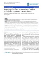
Figures 9 and 10 show the magnitude frequency response
of the largest filter, requiring 1144 LEs, and the smallest filter,
requiring 668 LEs, using the proposed design method.
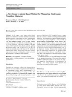
6. FPGA L AYOUT OF A PCLS BIT-SERIAL FIR
FILTER CORE
It is possible to visualize the implementation of a PCLS bit-
serial FIR filter core in the JBits Boardscope tool [17]. Oper-
ational verification of the core is also possible in the Board-
scope environment using the virtex device simulator (Vir-
texDS) [18]. Figure 11 illustrates the packing density of the
bit-serial library components as they a re placed in a PCLS
bit-serial FIR filter core with 95 taps and a PSR of 49.9 dB.
The only unused area of the FPGA within the bounding box
is the eight LEs at the bottom right corner of the box.
The core pictured in Figure 11 occupies 1071 LEs if
fanout buffers are not counted. The bounding box of the
core is 18 CLBs wide and 16 CLBs high. The fanout for the
pictured core has been limited to a maximum of 25 input
nets for any output signal resulting in 73 additional LEs for
fanout buffers. The bounding box contains 1152 LEs, includ-
ing fanout buffers; the filter occupies 1144 LEs (eight LEs are
allocated but are unused in this implementation).
0 0.5 1 1.5 2 2.5 3
Frequency (rad)
−90
−80
−70
−60
−50
−40
−30
−20
−10
0
Magnitude (dB)
Hardware cost = 1071 LEs
Hardware cost = 634 LEs
Figure 9: Magnitude frequency response for the filters with the
hardware cost of 1144 and 668 LEs for Adams’ filter (95 taps,
passband ripple = 1 dB, passband cutoff = 0.125π rad, stopband
cutoff
= 0.1608π rad, and minimum stopband attenuation =
43.22 dB).
0 0.05 0.1 0.15 0.2 0.25 0.3 0.35
Frequency (rad)
−1
−0.8
−0.6
−0.4
−0.2
0
0.2
Magnitude (dB)
Hardware cost = 1071 LEs
Hardware cost = 634 LEs
Figure 10: Magnitude frequency response of the passband for the
filters with the hardware cost of 1144 and 668 LEs for Adams’ fil-
ter (95 taps, passband ripple
= 1 dB, passband cutoff = 0.125π
rad, stopband cutoff = 0.1608π rad, and minimum stopband
attenuation = 43.22 dB).
Using the method presented in this paper, the 95 tap
PCLS bit-serial FIR digital filter can be designed and the bit-
stream can be created in approximately 4 minutes using a
950 MHz AMD Duron PC.
564 EURASIP Journal on Applied Signal Processing
16 CLBs high
18 CLBs wide
Eight
unused
LEs
Figure 11: Visualization of bit-serial component library subcores
as they are placed in a bit-serial FIR filter core with 95 taps and a
PSR of 49.9 dB. The device shown is the VirtexDS simulation of the
Xilinx Virtex XCV50 part, the smallest Virtex device.
REFERENCES
[1] A. Antoniou, Digital Filters, Analysis, Design, and Applications,
McGraw-Hill, New York, NY, USA, 1993.
[2] R. J. Andraka, “FIR filter fits in an FPGA using a bit serial
approach,” in Proc. 3rd Annual PLD Conference, Manhasset,
NY, USA, March 1993.
[3] S. He and M. Torkelson, “FPGA implementation of FIR filters
using pipelined bit-serial canonical signed digit multipliers,”
in Custom Integrated Circuits Conference (CICC ’94), pp. 81–
84, San Diego, Calif, USA, May 1994.
[4] Y. C. Lim, J. B. Evans, and B. Liu, “An efficient bit-serial FIR
filter architecture,” Circuits, Systems, and Signal Processing,
vol. 14, no. 5, pp. 639–651, 1995.
[5] P. B. James-Roxby, “Designing application-specific cores us-
ing JBits: a run-time parameterizable FIR filter,” in Recon-
figurable Technology: FPGAs and Reconfigurable Processors for
Computing and Communications III, vol. 4525 of SPIE Pro-
ceedings, pp. 18–26, Denver, Colo, USA, August 2001.
[6] J. W. Adams and J. L. Sullivan, “Peak-constrained least squares
optimization,” IEEE Trans. Signal Processing, vol. 46, pp. 306–
321, February 1998.
[7] J. W. Adams, “FIR digital filters with least-squares stopbands
subject to peak-gain constraints,” IEEE Trans. Circuits and
Systems, vol. 39, no. 4, pp. 376–388, 1991.
[8] T. W. Fox and L. E. Turner, “ The design of peak constrained
least squares FIR filters with low complexity finite precision
coefficients,” in Proc. IEEE Int. Symp. Circuits and Systems,
vol. 2, pp. 605–608, Sydney, Australia, May 2001.
[9] T. W. Fox and L. E. Turner, “ The design of peak constrained
least squares FIR filters with low complexity finite precision
coefficients,” IEEE Transactions on Circuits and Systems II, vol.
49, pp. 151–154, February 2002.
[10] R. I. Hartley and K. K. Parhi, Digit-Serial Computation,
Kluwer Academic Publishers, Boston, Mass, USA, 1995.
[11] S. A. Guccione and D. Levi, “Run-Time Parameteriz-
able cores,” in Proc. 9th International Workshop on Field-
Programmable Logic and Applications, FPL ’99, pp. 215–222,
Glasgow, UK, August–September 1999.
[12] S. A. Guccione, D. Levi, and P. Sundararajan, “JBits: Java-
based interface for reconfigurable computing,” in 2nd Annual
Military and Aerospace Applications of Programmable Devices
and Technologies (MAPLD ’99), The Johns Hopkins Univer-
sity, Laurel, Md, USA, September 1999.
[13] J. B. Ballagh, “An FPGA-based run-time reconfigurable 2-D
discrete wavelet transform core,” M.S. thesis, Virginia Poly-
technic Institute and State University, Blacksburg, Va, USA,
June 2001.
[14] J. Valls, M. M. Peiro, T. Sansaloni, and E. Boemo, “Design
and FPGA implementation of digit-serial FIR filters,” in Proc.
5th IEEE International Conference on Electronics, Circuits and
Systems (ICECS ’98), vol. 2, pp. 191–194, Lisboa, Portugal,
September 1998.
[15] Virtex
TM
2.5 V Field Programmable Gate Arrays—Final Prod-
uct Specification, May 2000, .
[16] E. Keller, “JRoute: A run-time routing API for FPGA hard-
ware,” in Parallel and Distributed Processing, J. Romlin et al.,
Eds., vol. 1800 of Lecture Notes in Computer Science, pp. 874–
881, Springer-Verlag, Berlin, May 2000.
[17] D. Levi and S. A. Guccione, “BoardScope: a debug tool for re-
configurable systems,” in Configurable Computing Technology
and Its Uses in High Performance Computing, DSP and Systems
Engineering, Proc. SPIE Photonics East,J.Schewel,Ed.,vol.
3526 of SPIE Proceedings, Bellingham, Wash, USA, November
1998.
[18] S. McMillan, B. Blodget, and S. Guccione, “VirtexDS: a device
simulator for Virtex,” in Reconfigurable Technology: FPGAs for
Computing and Applications II, vol. 4212 of SPIE Proceedings,
pp. 50–56, Bellingham, Wash, USA, November 2000.
Alex Carreira received a B.S. degree in elec-
trical engineering from the University of
Calgar y, Canada in 1999. He is presently
completing an M.S. degree in electrical en-
gineering at the University of Calgary. His
main research interests are digital signal
processing with programmable logic de-
vices, configurable and reconfigurable com-
puting, and rapid prototyping of systems
for programmable logic devices.
Trevor W. Fox received the B.S. and Ph.D.
degrees in electrical engineering from the
University of Calgary in 1999 and 2002, re-
spectively. He is presently working for Intel-
ligent Engines in Calgary, Canada. His main
research interests include digital filter de-
sign, reconfigurable digital signal process-
ing, and rapid prototyping of digital sys-
tems.
Laurence E. Turner received the B.S. and
Ph.D. degrees in electrical engineering from
the University of Calgary in 1974 and 1979,
respectively. Since 1979, he has been a fac-
ulty member at the University of Calgary
where he currently is a Full Professor i n
theDepartmentofElectricalandComputer
Engineering. His research interests include
digital filter design, finite precision effects
in digital filters, and the development of
computer-aided design tools for digital system design.