FUNCTION OVERVIEW DESCRIPTION SIEMENS SIP · EDITION NO 6 5 OVERCURRENT PROTECTION 7SJ600
Bạn đang xem bản rút gọn của tài liệu. Xem và tải ngay bản đầy đủ của tài liệu tại đây (448.8 KB, 12 trang )
<span class="text_page_counter">Trang 1</span><div class="page_container" data-page="1">
•Control via keyboard, DIGSI 4 or SCADA system •1 live status contact
<i>Numerical Overcurrent, Motor and Overload Protection Relay</i>
The SIPROTEC 7SJ600 is a numericalovercurrent relay which, in addition to itsprimary use in radial distribution networksand motor protection, can also be em-ployed as backup for feeder, transformerand generator differential protection.The SIPROTEC 7SJ600 provides definite-time and inverse-definite-time overcurrent protec-tion along with overload and negative-sequence protection for a very comprehen-sive relay package. In this way, equipmentsuch as motors can be protected againstasymmetric and excessive loading. Asym-metric short-circuits with currents that canbe smaller than the largest possible loadcurrents or phase interruptions are reliably
</div><span class="text_page_counter">Trang 2</span><div class="page_container" data-page="2"><i>Wide range of applications</i>
The SIPROTEC 7SJ600 is a numerical overcurrent relay which, in addition to its primary use in radial distribution networks and motor protection, can also be em-ployed as backup for feeder, transformer and generator differential protection. The SIPROTEC 7SJ600 provides defi-nite-time and inverse-time overcurrent protection along with overload and nega-tive-sequence protection for a very com-prehensive relay package. In this way, equipment such as motors can be pro-tected against asymmetric and excessive loading. Asymmetric short-circuits with currents that can be smaller than the larg-est possible load currents or phase inter-ruptions are reliably detected.
The integrated control function allows simple control of a circuit-breaker or disconnector (electrically operated/motor-ized switch) via the integrated HMI, DIGSI 3 or DIGSI 4 (≥ 4.3) or SCADA
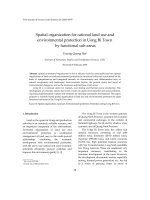
Fig. 5/20 Function diagram
50, 50N <i>I>, I>>, I>>>I</i><small>E</small><i>>, I</i><small>E</small>>>
Definite time-overcurrent protection (phase/neutral)
51, 51N <i>I</i><small>p</small><i>, I</i><small>Ep</small> Inverse time-overcurrent protection (phase/neutral)
46 <i>I</i><small>2</small>> Phase-balance current protection (negative-sequence protection)
74TC Trip circuit supervision breaker control
</div><span class="text_page_counter">Trang 3</span><div class="page_container" data-page="3">The relay contains all the components needed for
•Acquisition and evaluation of measured values
•Operation and display
•Output of signals and trip commands •Input and evaluation of binary signals has terminals accessible from the rear. The surface-mounting version has terminals accessible from the front.
<i>Siemens SIP · Edition No. 6</i>
The definite-time overcurrent function is based on phase-selective measurement of the three phase currents and/or earth cur-rent.
<i>Optionally, the earth (ground) current I</i>
<small>E</small>(Gnd) is calculated or measured from the
<i>three line currents I</i>
<small>L1</small><i>(I</i>
<small>A</small><i>), I</i>
<small>L2</small><i>(I</i>
<small>B</small>) and
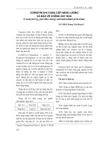
Fig. 5/22 Definite-time overcurrent characteristic
The definite-time overcurrent protection for the 3 phase currents has a low-set
<i>overcurrent element (I>), a high-setovercurrent element (I>>) and a high-setinstantaneous-tripping element (I>>>).</i>
Intentional trip delays can be parameteriz-ed from 0.00 to 60.00 seconds for the low-set and high-set overcurrent
<i>elements. The instantaneous zone I>>></i>
trips without any intentional delay. The definite-time overcurrent protection for the earth (ground) current has a low-set
<i>overcurrent element (I</i>
<small>E</small>>) and a high-set
<i>overcurrent element (I</i>
<small>E</small>>>).
Intentional trip delays can be parameteri-zed from 0.00 to 60.00 seconds.
<i>Available inverse-time characteristic</i>
In addition, invese-time overcurrentprotection characteristics (IDMTL)can be activated.
</div><span class="text_page_counter">Trang 4</span><div class="page_container" data-page="4"><i>Thermal overload protection (ANSI 49)</i>
<i>Siemens SIP · Edition No. 6</i>
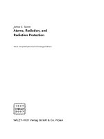
Fig. 5/24 Tripping characteristic of the negative-sequence protection function
<i>Negative-sequence protection (I2>>,I2>/ANSI 46 Unbalanced-load protection)</i>
The negative-sequence protection (see Fig. 5/24) detects a phase failure or load unbal-ance due to network asymmetry. Interrup-tions, short-circuits or crossed connections to the current transformers are detected. Furthermore, low level single-phase and two-phase short-circuits (such as faults be-yond a transformer) as well as phase inter-ruptions can be detected.
This function is especially useful for mo-tors since negative sequence currents cause impermissible overheating of the rotor. In order to detect the unbalanced load, the ratio of negative phase-sequence current to rated current is evaluated.
<i>I</i>
<small>2</small>= Negative-sequence current
<i>T</i>
<small>12</small>= Tripping time
<i>Transformer protection</i>
The high-set element permits current co-ordination where the overcurrent element functions as a backup for the lower-level protection relays, and the overload func-tion protects the transformer from thermal overload. Low-current single-phase faults on the low voltage side that result in nega-tive phase-sequence current on the high-voltage side can be detected with the nega-tive-sequence protection.
For further details please refer to part 2 “Overview”.
<i>Thermal overload protection (ANSI 49)</i>
The thermal overload protection function provides tripping or alarming based on a thermal model calculated from phase currents.
Thermal overload protection without preload
For thermal overload protection without consideration of the preload current, the following tripping characteristic applies only when
<i>I≥ 1.1 ⋅ I</i>
<small>L</small><i>For different thermal time constants T</i>
<small>L</small>,
<i>the tripping time t is calculated in </i>
accor-dance with the following equation:
<i>The reset threshold is above 1.03125 · I/I</i>
<small>N</small>Thermal overload protection with preload The thermal overload protection with con-sideration of preload current constantly updates the thermal model calculation regardless of the magnitude of the phase
<i>currents. The tripping time t is calculated</i>
in accordance with the following tripping characteristic (complete memory in accor-dance with IEC 60255-8).
t= Tripping time after beginning of the thermal overload
<i>Cold load pickup</i>
By means of a binary input which can be wired from a manual close contact, it is possible to switch the overcurrent pickup settings to less sensitive settings for a pro-grammable duration of time. After the set time has expired, the pickup settings auto-matically return to their original setting. This can compensate for initial inrush when energizing a circuit without compro-mising the sensitivity of the overcurrent elements during steady state conditions.
<i>3-pole multishot auto-reclosure(AR, ANSI 79)</i>
Auto-reclosure (AR) enables 3-phase auto-reclosing of a feeder which has previously been disconnected by time-overcurrent protection.
<i>Trip circuit supervision(ANSI 74TC)</i>
One or two binary inputs can be used for the trip circuit monitoring.
The relay permits circuit-breakers to beopened and closed without command feed-back. The circuit-breaker/disconnector maybe controlled by DIGSI, or by the integratedHMI, or by the LSA/SCADA equipmentconnected to the interface.
</div><span class="text_page_counter">Trang 5</span><div class="page_container" data-page="5"><i>Switch-onto-fault protection</i>
If switched onto a fault, instantaneous trip-ping can be effected. If the internal control function is used (local or via serial inter-face), the manual closing function is avail-able without any additional wiring. If the control switch is connected to a circuit-breaker bypassing the internal control function, manual detection using a binary input is implemented.
<i>Busbar protection(Reverse interlocking)</i>
Binary inputs can be used to block any of the six current stages. Parameters are as-signed to decide whether the input circuit is to operate in open-circuit or closed-cir-cuit mode. In this case, reverse interlocking provides high-speed busbar protection in radial or ring power systems that are opened at one point. The reverse inter-locking principle is used, for example, in medium-voltage power systems and in switchgear for power plants, where a high-voltage system transformer feeds a busbar section with several medium-voltage outgoing feeders.
<i>Siemens SIP · Edition No. 6</i>
<i>5/23</i>
<i>Protection functions</i>
Fig. 5/26 Wiring communication
For convenient wiring of the RS485 bus,
use bus cable system 7XV5103 (see part 15 of this catalog).
<i>Motor protection</i>
Fig. 5/25 Reverse interlocking
<i>Serial data transmission</i>
A PC can be connected to ease setup of the relay using the Windows-based program DIGSI which runs under MS-Windows. It can also be used to evaluate up to 8 oscillographic fault records, 8 fault logs and 1 event log containing up to 30 opera-tional indications. The SIPROTEC 7SJ600 transmits a subset of data via
For short-circuit protection, e.g. elements
<i>I>> (50) and I</i>
<small>E</small>(50N) are available. The stator is protected against thermal overload byϑ
<small>s</small><i>> (49), the rotor by I</i>
<small>2</small>> (46), starting time supervision (48).
<i>Motor starting time supervision (ANSI 48)</i>
The start-up monitor protects the motor against excessively long starting. This can occur, for example, if the rotor is blocked, if excessive voltage drops occur when the motor is switched on or if excessive load torques occur. The tripping time depends
<i>t</i>
<small>TRIP</small>= Tripping time
<i>I</i>
<sub>rms</sub>= Actual current flowing
</div><span class="text_page_counter">Trang 6</span><div class="page_container" data-page="6"><i>Siemens SIP · Edition No. 6</i>
<i>Connection diagrams</i>
Fig. 5/27
Connection of 3 CTs with measurement of the phase currents
Fig. 5/28
Connection of 3 CTs with measurement of the earth (ground) current
Fig. 5/30
Sensitive earth-fault protection (3 -times increased sensitivity) Fig. 5/29
Connection of 2 CTs only for isolated or resonant-earthed (grounded) power systems
Fig. 5/31 Example of typical wiring
</div><span class="text_page_counter">Trang 7</span><div class="page_container" data-page="7"><i>Siemens SIP · Edition No. 6</i>
<i>Rated frequency f</i><sub>N</sub> 50/60 Hz (selectable) Overload capability current path
<i>Power supply via integrated DC/DC converter</i>
<i>Rated auxiliary voltage V</i><small>aux</small>/ Bridging time during failure/
short-circuit of auxiliary voltage <i>≥ 50 ms at V</i><small>aux</small>≥ 110 V DC
Signal/alarm relays 2 (marshallable) Contacts per relay 1 CO
<i>Heavy-duty (command) contacts</i>
Trip relays, number 2 (marshallable)
Test voltage 2.8 kV DC for 1 min
Connection Data cable at housing terminals, two data wires, one frame reference, for connection of a personal computer or similar; core pairs with individual and common screening, screen must be earthed (grounded), communica-tion possible via modem
Transmission speed As delivered 9600 baud
Standards IEC 60255-5, ANSI/IEEE C37.90.0 High-voltage test (routine test)
Except DC voltage supply input
High-voltage test (type test) Between open contacts of trip
Impulse voltage test (type test) all circuits, class III
5 kV (peak), 1.2/50 µs, 0.5 J, 3 positive and 3 negative impulses at intervals of 5 s
</div><span class="text_page_counter">Trang 8</span><div class="page_container" data-page="8"><i>Siemens SIP · Edition No. 6</i>
<i>Technical data</i>
<i>EMC tests for interference immunity; type tests</i>
Standards IEC 60255-6; IEC 60255-22
IEC 60255-22-2, class III and IEC 61000-4-2, class III frequency, 200 Hz, duty cycle 50 % Fast transient interference/bursts
IEC 60255-22-4 and IEC 61000-4-4, class III
2 kV, 5/50 ns, 5 kHz, burst length 15 ms, repetition rate 300 ms, both
<i>polarities, R</i><small>i</small>= 50Ω,duration 1 min Conducted disturbances induced by
<i>EMC tests for interference emission; type tests</i>
Standard EN 50081-* (generic standard) Conducted interference voltage, aux.
voltage CISPR 22, EN 55022, DIN VDE 0878 Part 22, limit value class B
150 kHz to 30 MHz
Interference field strength CISPR 11, EN 55011, DIN VDE 0875 Part 11, limit value class A
30 to 1000 MHz
<i>Mechanical stress tests</i>
<i>Vibration, shock and seismic vibration</i>
Sweep rate 1 octave/min 20 cycles in 3 orthogonal axes Shock
IEC 60255-21-2, class 1
<i>Half-sine, acceleration 5 g, duration</i>
11 ms, 3 shocks in each direction
Sweep rate 1 octave/min 1 cycle in 3 orthogonal axes
Sweep rate 1 octave/min 20 cycles in 3 orthogonal axes Shock
IEC 60255-21-2, class 1 IEC 60068-2-27
<i>Half-sine, acceleration 15 g ,</i>
duration 11 ms, 3 shocks in each direction of 3 orthogonal axes Continuous shock
IEC 60255-21-2, class 1 IEC 60068-2-29
<i>Half-sine, acceleration 10 g</i>
duration 16 ms, 1000 shocks in each direction of 3 orthogonal axes
<i>Climatic stress tests</i>
(Storage and transport with standard works packaging)
–20 °C to +70 °C / –4 °F to +158 °F –25 °C to +55 °C / –13 °F to +131 °F –25 °C to +70 °C / –13 °F to +158 °F
Mean value per year≤ 75 % relative humidity, on 30 days per year 95 % relative humidity, condensation not permissible
</div><span class="text_page_counter">Trang 9</span><div class="page_container" data-page="9"><i>Siemens SIP · Edition No. 6</i>
<i>Pickup times I>, I>>, I</i><sub>E</sub><i>>, I</i><sub>E</sub>>> At 2 x setting value, without
<i>Delay time T for I>>, I</i><sub>E</sub>>> 0 s to 60 s (steps 0.01 s) Tripping time characteristics acc. to IEC
<i>with current I/I</i><small>N</small>≤ 1.5
<i>with current I/I</i><small>N</small>> 1.5 Stage delay times
<i>Auto-reclosure (option) (ANSI 79)</i>
Number of possible shots Auto-reclose modes
1 up to 9 3-pole Dead times for 1<sup>st</sup>to 3<sup>rd</sup>shot
for 4<sup>th</sup>and any further shot
0.05 s to 1800 s (steps 0.01 s) 0.05 s to 1800 s (steps 0.01 s)
Reclaim time after successful AR 0.05 s to 320 s (steps 0.01 s) Lock-out time after
unsuccessful AR
0.05 s to 320 s (steps 0.01 s)
Reclaim time after manual close 0.50 s to 320 s (steps 0.01 s) Duration of RECLOSE command 0.01s to 60 s (steps 0.01 s)
</div><span class="text_page_counter">Trang 10</span><div class="page_container" data-page="10"><i>Siemens SIP · Edition No. 6</i>
<i>Technical data</i>
<i>Thermal overload protection with memory (ANSI 49)(total memory according to IEC 60255-8)</i>
Setting ranges
Factor k acc. to IEC 60255-8 Thermal time constantτ<small>th</small>
Thermal alarm stageΘ<small>alarm</small>/Θ<small>trip</small>
Prolongation factor at motor
<i>stand-still k</i><small>τ</small>
0.40 to 2 (steps 0.01) 1 to 999.9 min (steps 0.1 min) 50 to 99 % referred to trip tempera-ture rise (steps 1 %)
Influence variables referred to k<i>⋅ I</i><small>N</small>
Auxiliary DC voltage in the range
<i>Without pickup value I</i><sub>L</sub><i>/ I</i><sub>N</sub> 0.4 to 4 (steps 0.1)
<i>Memory time multiplier T</i><sub>L</sub>
Total storage time (fault detec-tion or trip command = 0 ms)
Max. storage period per fault
<i>event T</i><small>max</small>
<i>Pre-trigger time T</i><sub>pre</sub> <i>Post-fault time T</i><sub>post</sub>
Sampling rate
Max. 8 fault records
Max. 5 s, incl. 35 power-fail safe selectable pre-trigger and post-fault time
0.30 to 5.00 s (steps 0.01 s)
0.05 to 0.50 s (steps 0.01s) 0.05 to 0.50 s (steps 0.01 s) 1 instantaneous value per ms at 50 Hz 1 instantaneous value per 0.83 ms at
<i>Thermal overload values</i>
Calculated temperature rise
<i>Fault event logging</i>
Storage of indications of the last 8
<i>Trip circuit supervision</i>
With one or two binary inputs
<i>Circuit-breaker trip test</i>
With live trip or trip/reclose cycle (version with auto-reclosure)
<i>CE conformity</i>
This product is in conformity with the Directives of the European Commu-nities on the harmonization of the laws of the Member States relating to electromagnetic compatibility (EMC Council Directive 89/336/EEC) and electrical equipment designed for use within certain voltage limits (Council Directive 73/23/EEC).
This unit conforms to the international standard IEC 60255, and the Ger-man standard DIN 57435/Part 303 (corresponding to VDE 0435/Part 303). The unit has been developed and manufactured for application in an industrial environment according to the EMC standards.
This conformity is the result of a test that was performed by Siemens AG in accordance with Article 10 of the Council Directive complying with the generic standards EN 50081-2 and EN 50082-2 for the EMC Directive and standard EN 60255-6 for the “low-voltage Directive”.
</div><span class="text_page_counter">Trang 11</span><div class="page_container" data-page="11"><i>Siemens SIP · Edition No. 6</i>
<i>7SJ600 numerical overcurrent, motor and overload protection relay 7SJ600<b>ă ăăAă0 ăDăă</b></i>
Binary input voltage 24 to 250 V DC with isolated RS485 port
For panel surface mounting, terminals on the side
<i>B</i>
With communication cable for the
7SJ600 numerical overcurrent, motor and overload protection relay Length 1 m
PC adapter
<i>Converter, full-duplex,</i>
<i>fiber-optic cable RS485 with built-in power supply unit</i>
Auxiliary voltage 24 to 250 V DC and 110/230 V AC <i>7XV5650- 0BA00</i>
2) Transition between the two auxiliary voltage ranges can be selected by means of jumpers.
3) Only when position 16 is not “1” (with U<small>L</small>-listing). 4) Possible versions see part 13.
* RS485 bus system up to 115 kbaud
RS485 bus cable and adaptor 7XV5103-oAAoo; see part 13.
</div>