Lab4 HCMUT
Bạn đang xem bản rút gọn của tài liệu. Xem và tải ngay bản đầy đủ của tài liệu tại đây (51.71 KB, 5 trang )
<span class="text_page_counter">Trang 1</span><div class="page_container" data-page="1">
• graphical determination of modulus of elasticity (p.80)
• determination of modulus of elasticity in tension and flexural stress • mechanical strain gauges, electrical resistant gauges
• basic strain at basic loading ( (chapter 15.2.3, p.84)
<b>2. Procedure </b>
The students will be divided into 3 groups, each will measure the modulus of elasticity in the flexural stress of the different materials The strain will be measured by the electrical resistance gauge with the help of apparatus TSA. The principal of the measuring is described in the chapter 15.2.2.
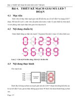
<i>Scheme of measuring: </i>
<b><small> </small></b>
Measuring:
Material will be loaded gradually and after each loading step the load goes back to the basic load F<small>0</small>. Scheme of the loading will be given at the lesson.
1. Switch on the apparatus
2. Zero the apparatus by the button 0
</div><span class="text_page_counter">Trang 2</span><div class="page_container" data-page="2"><small>BUM 1 LAB 4 </small>
4. After the stabilization read the value of deformation in promiles from the display
<b>and write it into the table as a 1<sup>st</sup> set of reading at the load F</b><small>1</small>[‰].
5. Unload to the load F<small>0</small> and write the value on the display as a 1<sup>st</sup> set at the load F<small>0</small>
[‰].
6. Repeat the procedure from points 3 to 5 for the loading F<small>2</small> and F<small>3</small>.
7. After each loading to F<small>i</small> there is necessary to unload to F<small>0</small> and write down the value of the deformation
8. During the one loading set the material shouldn’t be fully unloaded. 9. After one complete loading set switch off the apparatus.
<i><b>10. Measure the cross-sectional dimensions b, h [mm] at the place of measuring (be </b></i>
<i>careful not to touch glued gauge!), each dimension minimally twice. </i>
<i><b>11. Measure the distance between supports l [mm] </b></i>
<b>12. Repeat the measuring according points 1 to 9 and the results write down as a 2<sup>nd</sup></b>
• determine relative elastic deformations (elastic strain)
εεεε
<i><b><small>i</small></b></i> [‰] as a differences between readings at loading stages F<small>i</small> and subsequent reading at basic load F<small>0</small>for both sets and count their mean value
εεεε
<i><b><small>i</small><sup>´</sup></b></i> [‰]• count the basic strain
εεεε
<i><b><small>0</small></b></i> [‰] between zero and basic loading F<small>0</small> from similarity of<i><b>triangles (Fig. 44 – p.84) and count the total strain (</b></i>
εεεε
<i><b><small>i</small>´+ </b></i>εεεε
<i><b><small>0</small>) [‰] for each loading </b></i>step
• count the strain
σσσσ
<b><small>i </small></b>[MPa] at each loading step according the type of loading flexural stress, tension)• count the modulus of elasticity E<i><b><small>i </small></b></i> [MPa] from Hook’s law
• count mean value of the modulus of elasticity E [MPa] from all loading stages
<i>Modulus of elasticity in tension (form LAB 4:a) Modulus of elasticity in flexural stress) </i>
• the data, measured on the steel, will be given
• the mechanical gauges (Fig. 40 – p. 81) were used for measuring
• determine the real deformation
∆∆∆∆
<i><b>l [mm] as a differences between readings at </b></i>loading stages F<small>i</small> and at basic load F<small>0</small>
• count the relative strains (relative deformations)
εεεε
<i><b><small>i </small></b></i> [‰] from the real deformations<i><b>and the original gauge length (l<small>01</small>, l<small>02</small></b></i>)
• the rest of the determination is the same as a determination of modulus of elasticity in flexural stress
<i>For protocol you can use the form attached. If you use the hand made form, it has </i>
</div><span class="text_page_counter">Trang 3</span><div class="page_container" data-page="3"><small>BUM 1 LAB 4 </small>
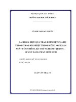
<b>LAB 4: Modulus of elasticity </b>
<small>(all calculations, given data)</small>
</div><span class="text_page_counter">Trang 5</span><div class="page_container" data-page="5"><b> 2 mechanical strain gauges </b>
1<sup>st</sup> gauge 2<sup>nd</sup> gauge 1. 2. 1. 2. mean ε<small>i</small>´
</div>