ANSIASHRAE ADDENDUM A TO ANSIASHRAE STANDARD 15-2019 SAFETY STANDARD FOR REFRIGERATION SYSTEMS
Bạn đang xem bản rút gọn của tài liệu. Xem và tải ngay bản đầy đủ của tài liệu tại đây (1016.16 KB, 17 trang )
<span class="text_page_counter">Trang 1</span><div class="page_container" data-page="1">
<b>ANSI/ASHRAE Addendum a toANSI/ASHRAE Standard 15-2019Safety Standard forRefrigeration Systems</b>
Approved by the ASHRAE Standards Committee on February 1, 2020; by the ASHRAE Board of Directors on February 5,2020; and by the American National Standards Institute on February 6, 2020.
This addendum was approved by a Standing Standard Project Committee (SSPC) for which the Standards Committee hasestablished a documented program for regular publication of addenda or revisions, including procedures for timely, docu-mented, consensus action on requests for change to any part of the standard. Instructions for how to submit a change canbe found on the ASHRAE
<sup>®</sup>website (www.ashrae.org/continuous-maintenance).
The latest edition of an ASHRAE Standard may be purchased on the ASHRAE website (www.ashrae.org) or fromASHRAE Customer Service, 1791 Tullie Circle, NE, Atlanta, GA 30329-2305. E-mail: Fax: 678-539-2129. Telephone: 404-636-8400 (worldwide), or toll free 1-800-527-4723 (for orders in US and Canada). For reprint per-mission, go to www.ashrae.org/permissions.
© 2020 ASHRAE ISSN 1041-2336
print or digital form is not permitted without ASHRAE's prior written permission.
</div><span class="text_page_counter">Trang 2</span><div class="page_container" data-page="2"><small>ASHRAE is a registered trademark of the American Society of Heating, Refrigerating and Air-Conditioning Engineers, Inc.ANSI is a registered trademark of the American National Standards Institute.</small>
<b><small>SPECIAL NOTE</small></b>
<i><small>This American National Standard (ANS) is a national voluntary consensus Standard developed under the auspices of ASHRAE. Consensus is defined by the</small></i>
<small>American National Standards Institute (ANSI), of which ASHRAE is a member and which has approved this Standard as an ANS, as “substantial agreementreached by directly and materially affected interest categories. This signifies the concurrence of more than a simple majority, but not necessarily unanimity.Consensus requires that all views and objections be considered, and that an effort be made toward their resolution.” Compliance with this Standard isvoluntary until and unless a legal jurisdiction makes compliance mandatory through legislation. </small>
<small>ASHRAE obtains consensus through participation of its national and international members, associated societies, and public review.</small>
<small>ASHRAE Standards are prepared by a Project Committee appointed specifically for the purpose of writing the Standard. The Project CommitteeChair and Vice-Chair must be members of ASHRAE; while other committee members may or may not be ASHRAE members, all must be technicallyqualified in the subject area of the Standard. Every effort is made to balance the concerned interests on all Project Committees. </small>
<small>The Senior Manager of Standards of ASHRAE should be contacted fora. interpretation of the contents of this Standard,</small>
<small>b. participation in the next review of the Standard,</small>
<small>c. offering constructive criticism for improving the Standard, ord. permission to reprint portions of the Standard.</small>
<small>ASHRAE uses its best efforts to promulgate Standards and Guidelines for the benefit of the public in light of available information and accepted industrypractices. However, ASHRAE does not guarantee, certify, or assure the safety or performance of any products, components, or systems tested, installed,or operated in accordance with ASHRAE’s Standards or Guidelines or that any tests conducted under its Standards or Guidelines will be nonhazardous orfree from risk.</small>
<b><small>ASHRAE INDUSTRIAL ADVERTISING POLICY ON STANDARDS</small></b>
<small>ASHRAE Standards and Guidelines are established to assist industry and the public by offering a uniform method of testing for rating purposes, by suggestingsafe practices in designing and installing equipment, by providing proper definitions of this equipment, and by providing other information that may serveto guide the industry. The creation of ASHRAE Standards and Guidelines is determined by the need for them, and conformance to them is completelyvoluntary.</small>
<small>In referring to this Standard or Guideline and in marking of equipment and in advertising, no claim shall be made, either stated or implied, that theproduct has been approved by ASHRAE.</small>
<b>ASHRAE Standing Standard Project Committee 15Cognizant TCs: 101, Custom Engineered Refrigeration Systems,</b>
<b>and 9.1, Large Building Air-Conditioning SystemsSPLS Liaison: Charles S. BarnabyASHRAE Staff Liaison: Steven C. Ferguson</b>
Sivakumar Gopalnarayanan Brian J. Rodgers*
<i>* Denotes members of voting status when the document was approved for publication</i>
<b>ASHRAE STANDARDS COMMITTEE 2019–2020</b>
<i>Wayne H. Stoppelmoor, Jr., Chair</i> Susanna S. Hanson Lawrence J. Schoen
<i>Steven C. Ferguson, Senior Manager of Standards</i>
print or digital form is not permitted without ASHRAE's prior written permission.
</div><span class="text_page_counter">Trang 3</span><div class="page_container" data-page="3"><b>(This foreword is not part of this standard. It is merely informative and does not containrequirements necessary for conformance to the standard. It has not been processedaccording to the ANSI requirements for a standard and may contain material that hasnot been subject to public review or a consensus process. Unresolved objectors on infor-mative material are not offered the right to appeal at ASHRAE or ANSI.)</b>
<i>This addendum provides capacity factors for overpressure protection of pressure vessels andpressure equipment for a number of new refrigerants and expands the coverage of capacity fac-tors for existing refrigerants based on the design pressure for the portion of the system beingpressure protected. Because the capacity factors are now dependent on the equipment’s designpressure, there will be cases where the revised capacity factors are larger than individual val-ues for grouped refrigerants provided in previous editions to this standard. Such cases will notnecessarily dictate a larger relief valve for a given piece of equipment, because many pressurevessels will have a relief device that has a modestly larger capacity compared to the calculatedminimum required relief capacity for the pressure vessel. In addition, this addendum intro-duces a method for calculating pressure relief capacity factors for refrigerants not included inthe standard or for design pressures for current refrigerants that are outside of the ranges ofpressures listed in the pressure relief capacity factor tables.</i>
<i><b>Note: In this addendum, changes to the current standard are indicated in the text by </b></i>
under-lining (for additions) and strikethrough (for deletions) unless the instructions specifically tion some other means of indicating the changes.
<i><b>men-Replace Section 9.7.5 as shown. </b></i>
<i><b>9.7.5 The minimum required discharge capacity of the pressure relief device or fusible plug</b></i>
<i>for each pressure vessel shall be determined by the following formula:C = fDL</i>
<i>C</i> = <i>minimum required discharge capacity of the pressure relief device expressed as mass </i>
flow of air, lb/min (kg/s)
<i>D</i> = outside diameter of vessel, ft (m)
<i><b>9.7.5 The minimum required discharge capacity (C) of the pressure relief device or fusible</b></i>
<i>plug for each pressure vessel shall be determined using the methods in this section.</i>
<i>The minimum required discharge capacity (C) shall be the largest value determined by</i>
consideration of potential thermal exposure from both external heat sources in accordance withSection 9.7.5.1 and internal heat sources in accordance with Section 9.7.5.2, with each casecalculated using Equation 9-AA. The calculated value of the minimum required relief devicedischarge capacity shall be rounded up to not less than two (2) significant figures.
<i>When one pressure relief device or fusible plug is used to protect more than one pressure sel, the required capacity shall be the sum of the capacities required for each pressure vessel.</i>
<i>ves-The pressure relief device set pressure shall be in accordance with Section 9.5, and the</i>
relieving pressure for calculations in this section shall be 1.1 times the relief device set pressure.
<b>Addendum a to Standard 15-2019</b>
print or digital form is not permitted without ASHRAE's prior written permission.
</div><span class="text_page_counter">Trang 4</span><div class="page_container" data-page="4">2 ANSI/ASHRAE Addendum a to ANSI/ASHRAE Standard 15-2019
<i>When the relieving pressure exceeds 90% of the refrigerant’s critical pressure, an engineering analysisshall determine the value of the pressure relief capacity factor (f)</i>
<i>C</i> = minimum required discharge capacity of the relief device expressed as mass flow of air, lb/min (kg/s)
<i>f</i> = pressure relief capacity factor that is dependent on type of refrigerant and vessel design pressure or protected equipment, lb/[ft<sup>2</sup>·min] (kg/[m<sup>2</sup>·s])
<i>A</i> = area of the pressure vessel or protected equipment (per Section 9.7.5.1 or 9.7.5.2), ft<sup>2</sup> (m<sup>2</sup>)
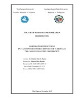
<i>Tables 9-1 through 9-6 provide values of pressure relief device capacity factors (f) for specificrefrigerants and pressure vessel design pressures calculated in accordance with this section. Thetables are arranged according to the refrigerant designation and the design pressure of the pressurevessel or protected equipment. Linear interpolation shall be used for determining capacity factorsfor intermediate design pressure values between tabulated values. Capacity factor values from</i>
Tables 9-1 through 9-6 shall not be extrapolated. Capacity factor values for other refrigerants or
<i>design pressures outside the range of the tables shall be calculated per the method in this section.The area (A) shall be calculated in accordance with Section 9.7.5.1 and Section 9.7.5.2. Thecapacity factor (f) shall be calculated using Equation 9-BB when the relieving pressure of the vesseldoes not exceed 90% of the refrigerant critical pressure.</i>
<i>H</i> = the heat flux from a thermal energy source originating from an external source or internal source in accordance with Sections 9.7.5.1 and 9.7.5.2, respectively, Btu/[ft<sup>2</sup>·min] (kW/m<sup>2</sup>)
<i>h<sub>fg</sub></i> = the refrigerant’s latent heat of vaporization evaluated at the relieving pressure (1.1 times the
<i>component design pressure), Btu/lb (kJ/kg)</i>
<i>r<sub>w</sub></i> = refrigerant to air mass flow rate conversion factor, dimensionless
<i><b>Table 9-1 Pressure Relief Devices Capacity Factor</b></i>
<i><b>RefrigerantValue of fWhen Used on the Lowside of a Limited-Charge Cascade System</b></i>
1.0 (0.082)
R-12, R-22, R-114, R-124, R-134a, R-401A,R-401B, R-401C, R-405A, R-406A, R-407C,R-407D, R-407E, R-409A, R-409B, R-411A,R-411B, R-411C, R-412A, R-414A, R-414B,R-500, R-1270
2.5 (0.203)
<i>C</i> = <i>f</i><i>A</i>
<i>h<sub>fg</sub>--- r</i> <i><sub>w</sub></i>=
print or digital form is not permitted without ASHRAE's prior written permission.
</div><span class="text_page_counter">Trang 5</span><div class="page_container" data-page="5"><i>The refrigerant to air mass flow rate conversion factor (r<sub>w</sub></i>) shall be calculated using tions 9-CC and 9-DD.
<i>C<sub>a</sub></i> = 356, a dimensionless constant for air
<i>T<sub>r</sub></i> = the absolute dew-point temperature of refrigerant evaluated at a relieving pressure of 1.1 times the relief device set pressure, °R (K)
<i>T<sub>a</sub></i> = the absolute temperature of standard air, 520°R (289 K)
<i>M<sub>r</sub></i> = the relative molar mass of the refrigerant in accordance with ASHRAE Standard 34<sup>1</sup>
<i>M<sub>a</sub></i> = the relative molar mass of air, 28.97
<i>k</i> = <i>the ratio of specific heats (c<sub>p</sub>/ c<sub>v</sub>) for saturated refrigerant vapor evaluated at a relieving </i>
pressure of 1.1 times the relief device set pressure
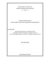
<i><b>9.7.5.1 External Heat Sources. The area (A) shall be the largest refrigerant-containing,</b></i>
<i>projected external surface area of the pressure vessel when viewed from any orientation. SeeFigure 9-1 for examples. The value of heat flux (H) shall be not less than 150 Btu/[min·ft</i><sup>2</sup>](28.4 kW/m<sup>2</sup>). Where combustible materials are within 20 ft (6.1 m) of a pressure vessel, the
<i>value of heat flux (H) shall be not less than 375 Btu/[min·ft</i><sup>2</sup>] (71.0 kW/m<sup>2</sup>). Where a heat
<i>source other than an external fire has potential to generate a larger heat flux (H) during </i>
operat-ing conditions and standby conditions as defined in Sections 9.2.1 and 9.2.1.2, or duroperat-ing otherabnormal conditions, the pressure relief device shall be sized based on the other heat source.
<i><b>9.7.5.2 Internal Heat Sources. The area (A) shall be the applicable refrigerant-containing</b></i>
<i>area for the pressure vessel or pressure-protected equipment that corresponds to the greatestinternal heat flux (H) expected during operating conditions or standby conditions as defined in</i>
Sections 9.2.1 and 9.2.1.2.
<i><small>k</small></i><small>+1</small><i><small>k</small></i> <small>1</small>=
print or digital form is not permitted without ASHRAE's prior written permission.
</div><span class="text_page_counter">Trang 6</span><div class="page_container" data-page="6">ANSI/ASHRAE Addendum a to ANSI/ASHRAE Standard 15-2019 4
<i><b>Table 9-1 Relief Device Refrigerant Capacity Factors, f, lb/[ft</b></i><b><sup>2</sup>·min] (I-P)</b>
<i><b>Design Pressure (psi, gage)</b></i>
</div><span class="text_page_counter">Trang 7</span><div class="page_container" data-page="7"><i><b>Table 9-1 Relief Device Refrigerant Capacity Factors, f, lb/[ft</b></i><b><sup>2</sup></b><i><b>·min] (I-P) (Continued)</b></i>
<i><b>Design Pressure (psi, gage)</b></i>
print or digital form is not permitted without ASHRAE's prior written permission.
</div><span class="text_page_counter">Trang 8</span><div class="page_container" data-page="8">ANSI/ASHRAE Addendum a to ANSI/ASHRAE Standard 15-2019 6
<i><b>Table 9-1 Relief Device Refrigerant Capacity Factors, f, lb/[ft</b></i><b><sup>2</sup></b><i><b>·min] (I-P) (Continued)</b></i>
<i><b>Design Pressure (psi, gage)</b></i>
print or digital form is not permitted without ASHRAE's prior written permission.
</div><span class="text_page_counter">Trang 9</span><div class="page_container" data-page="9"><i><b>Table 9-1 Relief Device Refrigerant Capacity Factors, f, lb/[ft</b></i><b><sup>2</sup></b><i><b>·min] (I-P) (Continued)</b></i>
<i><b>Design Pressure (psi, gage)</b></i>
print or digital form is not permitted without ASHRAE's prior written permission.
</div><span class="text_page_counter">Trang 10</span><div class="page_container" data-page="10">ANSI/ASHRAE Addendum a to ANSI/ASHRAE Standard 15-2019 8
<i><b>Table 9-2 Relief Device Refrigerant Capacity Factors, f, kg/[m</b></i><b><sup>2</sup>·s] (SI)</b>
<i><b>Design Pressure (kPa, gage)</b></i>
</div><span class="text_page_counter">Trang 11</span><div class="page_container" data-page="11"><i><b>Table 9-2 Relief Device Refrigerant Capacity Factors, f, kg/[m</b></i><b><sup>2</sup></b><i><b>·s] (SI) (Continued)</b></i>
<i><b>Design Pressure (kPa, gage)</b></i>
print or digital form is not permitted without ASHRAE's prior written permission.
</div><span class="text_page_counter">Trang 12</span><div class="page_container" data-page="12">10 ANSI/ASHRAE Addendum a to ANSI/ASHRAE Standard 15-2019
<i><b>Table 9-2 Relief Device Refrigerant Capacity Factors, f, kg/[m</b></i><b><sup>2</sup></b><i><b>·s] (SI) (Continued)</b></i>
<i><b>Design Pressure (kPa, gage)</b></i>
print or digital form is not permitted without ASHRAE's prior written permission.
</div><span class="text_page_counter">Trang 13</span><div class="page_container" data-page="13"><i><b>Table 9-2 Relief Device Refrigerant Capacity Factors, f, kg/[m</b></i><b><sup>2</sup></b><i><b>·s] (SI) (Continued)</b></i>
<i><b>Design Pressure (kPa, gage)</b></i>
print or digital form is not permitted without ASHRAE's prior written permission.
</div><span class="text_page_counter">Trang 14</span><div class="page_container" data-page="14">12 ANSI/ASHRAE Addendum a to ANSI/ASHRAE Standard 15-2019
<i><b>Table 9-3 Relief Device Refrigerant Capacity Factors, f, lb/[ft</b></i><b><sup>2</sup>·min] (I-P)</b>
</div><span class="text_page_counter">Trang 15</span><div class="page_container" data-page="15"><b>Informative Table 9-2 9-7 Atmospheric Pressure at Nominal Installation Elevation (Pa)Figure 9-1 External projected area examples for common pressure equipment.</b>
print or digital form is not permitted without ASHRAE's prior written permission.
</div><span class="text_page_counter">Trang 16</span><div class="page_container" data-page="16"><b>POLICY STATEMENT DEFINING ASHRAE’S CONCERNFOR THE ENVIRONMENTAL IMPACT OF ITS ACTIVITIES</b>
ASHRAE is concerned with the impact of its members’ activities on both the indoor and outdoor environment.ASHRAE’s members will strive to minimize any possible deleterious effect on the indoor and outdoor environment ofthe systems and components in their responsibility while maximizing the beneficial effects these systems provide,consistent with accepted Standards and the practical state of the art.
ASHRAE’s short-range goal is to ensure that the systems and components within its scope do not impact theindoor and outdoor environment to a greater extent than specified by the Standards and Guidelines as established byitself and other responsible bodies.
As an ongoing goal, ASHRAE will, through its Standards Committee and extensive Technical Committee structure,continue to generate up-to-date Standards and Guidelines where appropriate and adopt, recommend, and promotethose new and revised Standards developed by other responsible organizations.
<i>Through its Handbook, appropriate chapters will contain up-to-date Standards and design considerations as the</i>
material is systematically revised.
ASHRAE will take the lead with respect to dissemination of environmental information of its primary interest andwill seek out and disseminate information from other responsible organizations that is pertinent, as guides to updatingStandards and Guidelines.
The effects of the design and selection of equipment and systems will be considered within the scope of thesystem’s intended use and expected misuse. The disposal of hazardous materials, if any, will also be considered.
ASHRAE’s primary concern for environmental impact will be at the site where equipment within ASHRAE’s scopeoperates. However, energy source selection and the possible environmental impact due to the energy source andenergy transportation will be considered where possible. Recommendations concerning energy source selectionshould be made by its members.
print or digital form is not permitted without ASHRAE's prior written permission.
</div>