đồ án hệ thống truyền động design tramission system for truck on crane rail
Bạn đang xem bản rút gọn của tài liệu. Xem và tải ngay bản đầy đủ của tài liệu tại đây (927.77 KB, 32 trang )
<span class="text_page_counter">Trang 1</span><div class="page_container" data-page="1">
<b>HO CHI MINH UNIVERSITY OF TECHNOLOGYFALCUTY OF MECHANICAL ENGINEERING</b>
<b>TRANSMISSION SYSTEM PROJECT</b>
<b>Group CC01 – Project 1 – Data 1</b><b>DESIGN TRAMISSION SYSTEM FOR TRUCK ON CRANE RAIL</b>
<b>SEMESTER 232SCHOOL YEAR 2023-2024</b>
Instructor: Assoc. Prof. Nguyễn Tấn TiếnStudents:
Trần Vũ Hảo – 2025978Lê Anh Đạt – 2052938
<i>Ho Chi Minh City, January 12, 2024</i>
</div><span class="text_page_counter">Trang 2</span><div class="page_container" data-page="2">Nowadays, we live in Industry 4.0 which based on a digital platform and integrating smart device to optimize production technology. Applying technology to manufacture not only increase productivities, but also a safety workplace for humans. So all we need now it is very important to us to develop and improve our technical skills from the beginning of our university.Mechanical engineering is study of physics, mathematics and material science to design, analyze the kinematics and dynamics of a system, manufacture and maintain a mechanical system. It is foundation that many industries’ and product as car, plane, etc. All of that need a transmission system
In this transmission project, we design a mechanical system that transmit motion from the motor to the truck on the crane rail. During the period of time doing this project, we can reinforce all the knowledge from courses Kinematics and Dynamics of Machine, Machine Elements, Mechanical Engineering Drawing. Also, we improve the skills need for using engineering software such as CAD and Solid Work. With the instruction of Pro. Nguyễn Tấn Tiến.
</div><span class="text_page_counter">Trang 3</span><div class="page_container" data-page="3">Rail resistance force, F=3860(N )
Tangential velocity on the wheel, v=1.6 (m/s)Diameter of the wheel, D=330 (mm)Service life, L<small>h</small>=4 years=19200hours
One-direction working, 2 shifts per working day, 300 working days/ year, hour shift
</div><span class="text_page_counter">Trang 4</span><div class="page_container" data-page="4">8-CHAPTER 1: SELECTING THE MOTOR AND SPEED RATIO DISTRIBUTION...7
I. Transmission system diagram...7
II. Crane rail wheel parameters...7
II. Choosing the efficiency of the transmitting system...7
III. Choosing the motor... 7
V. Choosing transmission ratio...8
VI. Speed of shaft... 8
VII. Power of shafts:... 8
VIII. Torque of shafts...9
IX. Summary... 9
CHAPTER 2: DESIGN THE SPUR GEAR FOR THE SPEED REDUCER...10
I. Choosing the material... 10
II. Allowable stresses... 10
1. Fatigue limit stresses...10
2. Theorical operating cycles...10
3. Equivalent operating cycles...10
4. Lifespan factor...10
5. Safety coefficients...10
6. Allowable contact stress...10
7. Allowable bending stress...11
8. Allowable overload stress...11
9. Summary... 11
III. Center distance... 11
IV. Gear module...11
V. Teeth of gears...11
VI. Face width... 12
VII. Accuracy class...12
VII. Verify contact stess...12
IX. Verify bending stress...13
X. Force caculating of the Spur Gear...14
XI. Parameters of gear drive...14
CHAPTER 3: DESIGN THE SPUR GEAR FOR THE TRANSMISSION...15
I. Choosing the material... 15
II. Allowable stresses... 15
</div><span class="text_page_counter">Trang 5</span><div class="page_container" data-page="5">1. Fatigue limit stresses...15
2. Theorical operating cycles...15
3. Equivalent operating cycles...15
4. Lifespan factor...15
5. Safety coefficients...15
6. Allowable contact stress...15
7. Allowable bending stress...16
8. Allowable overload stress...16
9. Summary... 16
III. Center distance... 16
IV. Gear module...16
V. Teeth of gears...16
VI. Adjusting the gear profile...17
VII. Gear parameters... 17
VIII. Face width... 18
VII. Accuracy class...18
IX. Verify contact stess... 18
X. Verify bending stress...19
XI. Force caculating of the Spur Gear...20
XII. Summary... 20
II. Determine forces acting on the shaft...21
II. Determine and caculating Shaft I...21
1. Determine the preliminary diameter of shaft I...21
2. Caculating the distance between the sections of shaft I...21
3. Caculate force and moment apply on the shaft I...22
4. Determine diamter of each section and key:...24
III. Determine and caculating Shaft II...24
1. Determine the preliminary diameter of shaft II...24
2. Caculating the distance between the sections of shaft II...25
3. Caculate force and moment apply on the shaft II...25
4. Determine diamter of each section and key...26
IV. Re-caculating Shaft and Key...27
1. Re-caculaing shaft condisdering fatigue strength...27
2. Re-caculate strength condition of keyway...29
</div><span class="text_page_counter">Trang 6</span><div class="page_container" data-page="6">CHAPTER 6: DESIGN AND CACULATE ROLLING BEARING...30
I. Select bearings for shaft I...30
1. Choose type of bearing...30
2. Caculate the dynamic load...30
II. Select bearings for shaft II...30
1. Choose type of bearing...30
2. Caculate the dynamic load...31
CHAPTER 5: DESIGN FLEXIBLE COUPLING...32
I. Specification of flexible coupling...32
II. Caculate force apply on the flexible coupling...32
III. Strength of the coupling...32
CHAPTER 8: LUBRICATION...33
II.Lubrication condition...33
II. Select the type and of oil...33
CHAPTER 9: TOLERANCE AND ASSEMBLY TYPE SELECTION...34
I. Tolerance of key and key-way...34
II. Tolerance of spur gears...34
III. Tolerance assembly of bearing...34
IV. Tolerance assembly of oil seal...34
V. Tolerance assembly of caps of hub...34
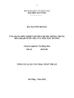
</div><span class="text_page_counter">Trang 7</span><div class="page_container" data-page="7"><b>DISTRIBUTIONI. Transmission system diagram</b>
Figure 1. Truck on crane rail system
<b>II. Crane rail wheel parameters</b>
The power of the wheel using the formula (2.11) [1]:P<small>lv</small>= <sup>Fv</sup>
1000<sup>=</sup>3860 1.6×
<b>II. Choosing the efficiency of the transmitting system</b>
The efficiency of each machine element is chosen based on the Table 2.3 [1].
Table 1.1. Efficiency of system
Transmission parts Symbols Efficiency factor
Therefore, the general efficiency of the transmitting system using formula (2.9) [1]:
</div><span class="text_page_counter">Trang 8</span><div class="page_container" data-page="8">η<small>sys</small>=η<small>sn</small>η<small>sr</small>η<small>rg</small> η<small>sg</small>η<small>cg</small>=0.93 × 0.96 ×0.99×0.98 0.98× ≈0.84
<b>III. Choosing the motor</b>
The general ratio of transmission is defined in the Table 2.4 [1]:u<small>gen</small>=u<small>gearreducer</small>u<small>geartrans</small>= (3 ữ 5) ì ( 4 ÷ 6)= (12 30÷ )
The primality rotation speed of motor is defined by the formula (2.18) [1]:
n<sub>sb</sub>=u<sub>gen</sub>n<sub>wheel</sub>=( 12 30÷ )ì92.6= ( 1111.2 2778ữ )rpmThe required power using formula (2.8) [1]:
From these condition, we choose the motor 3GBP132323−BDB developed by ABB company
Table 1.2. Motor parametersMotor ID <sup>Powe</sup>r
t (kg)3 GBP132323− 7.5 1450 14.5 0.81 89.3 49.4 73
<b>V. Choosing transmission ratio.</b>
From formula (2.18) in [1], recalculate the general transmission ratio of the system:
=<sup>1450</sup>92.6 <sup>≈ 15.66</sup>
We choose the gear reducer transmission ratio based on the Table 2.4 [1]:
Note: [∆u
]=4 % Allowable ratio error based on page 99 [1]
<b>VI. Speed of shaft.</b>
Speed of shaft I:n n= =1450(rpm)
</div><span class="text_page_counter">Trang 9</span><div class="page_container" data-page="9">Speed of shaft II:n<sub>II</sub>= <sup>n</sup><small>I</small>
u<small>gearreducer</small>=<sup>1450</sup><sub>4</sub> =362.5 (rpm)Speed of the working part:
n<sub>wheel</sub>= <sup>n</sup><small>II</small>
<b>VII. Power of shafts:</b>
Power of working part:P<small>lv</small>=6.176(kW)Power of shaft II:
P<small>II</small>= <sup>P</sup><small>lv</small>
= <sup>6.176</sup>
0.98 × 0.93× 0.99<sup>=6.845(kW)</sup>Power of shaft I:
P<small>I</small>= <sup>P</sup><small>II</small>
=<sub>0.99 ×0.96</sub><sup>6.845</sup> =7.202(kW)Power of motor shaft:
=9.55 ×10<small>6</small>×<sup>7.35</sup><sub>1450</sub>=48408.62(Nmm)Torque of shaft I:
T<small>II</small>=9.55 ×10<small>6</small>
× <small>II</small>
n<small>II</small>=9.55 ×10<small>6</small>
×<sup>6.845</sup><sub>362.5</sub>=180330.35(Nmm)Torque of wheel:
Transmission
</div><span class="text_page_counter">Trang 10</span><div class="page_container" data-page="10">Torque, Nm 48.41 47.43 180.03 636.94
</div><span class="text_page_counter">Trang 11</span><div class="page_container" data-page="11"><b>I. Choosing the material </b>
We choose C 45 steel with structure improvement method for designing the gear drive (following the Table 6.1). According to the table, we consider group I which has the hardness HB<small>1</small>=260 HB for the driving gear. For the driven gear, we should choose hardness according to the formula HB<sub>1</sub>≥H B<small>2</small>+ ( 10 ÷15)HB. So we choose HB<small>2</small>=245 HB
<b>II. Allowable stresses1. Fatigue limit stresses</b>
The limitation of contact stress of driving gear from the Table 6.2 [1]σ<small>Hlim 1</small>
<b>2. Theoretical operating cycles</b>
Driving gear’s contact operating cycles from formula (6.5) [1]:N<small>HO 1</small>=30 HB<small>1</small><sup>2.4</sup>=30 ×260<small>2.4</small>=18752418(cycles)
Driven gear’s contact operating cycles from formula (6.5) [1]:N<small>HO 1</small>=30 HB<small>2</small>
<b>3. Equivalent operating cycles</b>
Driving gear’s equivalent operating cycles from formula (6.7) [1]:N<small>HE1</small>=N<small>FE1</small>=60 n<small>I</small>L<small>h</small>c=60 ×1450 ×19200 ×1=1,67 10× <small>9</small>(cycles)Driven gear’s equivalent operating cycles from formula (6.7) [1]:
N<small>HE2</small>=N<small>FE2</small>=60 n<small>II</small>L<small>h</small>c=60 × 362.5× 19200×1=4,176 10× <small>8</small>
<b>4. Lifespan factor</b>
Driving gear’s life factor for contact stress:K<small>HL1</small>=1because N<small>HE1</small>>N<small>H 01</small>
Driven gear’s life factor for contact stress:K<sub>HL 2</sub>=1because N<sub>HE1</sub>>N<small>H 01</small>
Driving gear’s life factor for bending stress:K<small>FL 1</small>=1because N<small>HE1</small>>N<sub>H 01</sub>Driven gear’s life factor for bending stress:K<sub>FL 2</sub>=1 because N<sub>HE1</sub>>N<sub>H 01</sub>
<b>5. Safety coefficientsS</b>
Safety coefficientsSfor contact stress based on Table 6.2 [1]: S<sub>H</sub>=1.1Safety coefficientsSfor bending stress based on Table 6.2 [1]: S<sub>F</sub>=1.75
<b>6. Allowable contact stress</b>
Allowable contact stress for driving gear based on formula (6.1a) [1]
</div><span class="text_page_counter">Trang 12</span><div class="page_container" data-page="12">[
σ<sub>H 1</sub>]
=σ<small>Hlim 1</small><sup>0</sup>K<sub>HL 1</sub>S<small>H</small>
<b>7. Allowable bending stress</b>
Allowable bending stress for driving gear based on formula (6.1a) [1]
[
σ<small>F 1</small>]
=σ<small>Flim 1</small><b>8. Allowable overload stress</b>
Allowable overload contact stress based on formula (6.13) [1]
[
σ<small>H</small>]
<small>max</small>=2.8 σ<small>b</small>=2.8 ×650 1820= (MPa)Allowable overload bending stress based on formula (6.14) [1]
[
σ<small>F 1</small>]
<small>max</small>=0.8 σ<small>b</small>=0.8 ×650 520 ( MPa ) =<b>9. Summary</b>
Table 2.1. Properties of Spur gear material
Strength Stressσ<sub>b</sub>,MPa
YieldStressσ<sub>c h</sub>,MPa
K<sub>a</sub>=49.5 based on the Table 6.4 [1]ψ<sub>ba</sub>=0.4
ψ<small>bd</small>=0.53ψ<small>ba</small>( u+1)=0.53× 0.4 ×5=1.06 based on formula (6.16) [1]K<small>Hβ</small>=1.05 based on the Table 6.7 [1]
</div><span class="text_page_counter">Trang 13</span><div class="page_container" data-page="13"><b>1. Determine the preliminary diameter of shaft I</b>
Based on the equation (10.9) [1], we figure out the preliminary diameterof shaft I
√
T<sub>I</sub>0.2[τ]
<sup>=</sup>0.2× 20 <sup>=22.8(mm)</sup>where,
[τ]
– Allowable torsional stress,<sub>[τ]=15 ÷ 30 MPa according to page 188 in </sub>
[1][τ]=20 MPa – for shaft I and shaft II
We choose the preliminary diameter of shaft I based on the Table 10.2 [1]
d<sub>I</sub>=25 mm with the width of bearing b<sub>01</sub>=16 mm
<b>2. Calculating the distance between the sections of shaft I</b>
Following Table 10.3 and 10.4 [1] and equation 10.10, we figure out all the distance of shaft I:
The mayo length of half of coupling:l<small>m12</small>=(1.4 2.5÷ ) d<small>I</small>=( 35 62.5÷ )(mm)
We choose l<small>m12</small>=50 mm based on Table 16.10a and 16.10b [2]The mayo length of the driving gear:
l<sub>13</sub>=0.5
(
l<sub>m 13</sub>+ b<sub>01</sub>)
+k<sub>1</sub>+ k<sub>2</sub>=0.5 (55 16+ )+8+ 7=50.5 mmFinally, the distance between bearing 0 and bearing 1:l<small>11</small>=2l<small>13</small>=101 mm
Coefficient of k<sub>1</sub>,k<sub>2</sub>,k<sub>3</sub>∧h<sub>n</sub> can be choosen from the Table 10.3 [1]k<small>1</small>=8 ,k<small>2</small>=7 k<small>3</small>=15∧h<small>n</small>=15
<b>3. Calculate force and moment apply on the shaft I </b>
We consider the magnitude of forces acting on shaft I on the table below:
Table 4.2. Force acting on the shaft I
Magnitude, N 1897.36 690.58 340.9
</div><span class="text_page_counter">Trang 14</span><div class="page_container" data-page="14">According to the free body diagram in figure, we have force equation equilibrium and moment equation of equilibrium in the O<sub>yz</sub> surface as:
{
∑F<sub>y 0</sub>(↓¿ <sup>= F</sup><small>Ay</small>− F<small>r 1</small>+ F<small>Cy</small>=0¿∑M<small>A</small> (↺¿¿F<small>r 1</small>×AB− F<small>Cy</small>×AC=0¿
⇔
{
F<small>Ay</small>=345.29(N )F<sub>Cy</sub>=345.29(N )According to the free body diagram in figure, we have force equation equilibrium and moment equation of equilibrium in the O<small>xz</small> surface as:
¿ <sup>= F</sup><small>Ax</small>− F<sub>t 1</sub>+ F<sub>Cx</sub>+ F<sub>r</sub>=0¿∑M<sub>A</sub> (↺¿¿F<sub>t 1</sub>×AB− F<sub>Cx</sub>×AC− F<sub>r</sub>× AD=0¿
⇔
{
F<sub>Ax</sub>=1161.32(N)F<small>Cx</small>=395.14 (N )Table 4.3. Reaction force forces of bearing
Magnitude, N 1161.32 345.29 395.14 345.29After getting the value of forces, we draw the moment diagram for the shaft I
</div><span class="text_page_counter">Trang 16</span><div class="page_container" data-page="16">Based on the moment diagram, we calculate the bending moment M<sub>j</sub>and quivalent moment M<sub>j</sub>and equivalent moment M<sub>eqj</sub> at the section j along the length of shaft I by equation (10.15) and (10.16)
Similarly, we get:M<sub>10</sub>=0 NmmM<sub>11</sub>=73694.7 NmmM<small>12</small>=46353.87 NmmM<small>13</small>=41078.92 Nmm
From the equivalent moment we can figure out the diameter of the dangerous section follow equation (10.18)
Because the diameter of the driving gear is close to the diameter of the shaft. So we choose a seamless gear for the driving gear of shaft I. The diameter of shaft is chosen based on page 195 [1], we choose d<small>11</small>=40 mm for the seamess gear. So we can get other section diamter:
d<small>10</small>=30 mmd<small>11</small>=40 mmd<small>12</small>=30 mmd<sub>13</sub>=20 mm
From the diameter section of the flexible coupling d<small>13</small>=20 mm. We can choose the key based on the Table 9.1a and 9.1b
Table 4.4. Specification of key for shaft I
<b>III. Determine and calculating Shaft II</b>
<b>1. Determine the preliminary diameter of shaft II</b>
Based on the equation (10.9) [1], we figure out the preliminary diameterof the driven gear of reducer
</div><span class="text_page_counter">Trang 17</span><div class="page_container" data-page="17">d<small>II</small>=<sup>3</sup>
√
T<small>II</small>0.2× 20 <sup>=35.6(mm)</sup>Where,
[τ] – Allowable torsional stress, [τ]=15 ÷ 30 MPa according to page 188 in
[1][τ]=20 MPa – for shaft I and shaft II
We choose the preliminary diameter of shaft II based on the Table 10.2 [1]:
d<small>II</small>=40 mm with the width of bearing b<small>02</small>=23 mm
<b>2. Calculating the distance between the sections of shaft II</b>
Following Table 10.3 and 10.4 [1] and equation 10.10, we figure out all the distance of shaft II:
The mayo length of driving gear transmission:l<sub>m22</sub>=(1.2 1.5÷ ) d<sub>II</sub>=( 48 60÷ ) mm
Because the width of spur gear of the gear of transmission b<small>w1</small>=65 mm. Sowe choose l<small>m 22</small>=65 mm
The mayo length of the driven gear reducer:l<sub>m23</sub>=(1.2 1.5÷ ) d<sub>II</sub>=(30 ÷ 37.5) mm
Because the width of spur gear b<small>w 2</small>=50 mm. We choose l<small>m 23</small>=50 mmThe distance from the bearing 0 to the driving gear’s transmission
l<small>22</small>=−l<small>22</small>=0.5
(
l<small>m 22</small>+b<small>02</small>)
+k<small>3</small>+h<small>n</small>=0.5 ( 65 29+ )+15+15=77 mmThe distance from the bearing 0 to driving’s gear:l<sub>23</sub>=0.5
(
l<sub>m 23</sub>+b<sub>02</sub>)
+k<sub>1</sub>+k<sub>2</sub>=0.5 (50 29+ )+6+ 5=50.5 mmFinally, the distance between bearing 0 and bearing 1:l<small>21</small>=2 l<small>23</small>=101mm
We choose coefficient of k<small>1</small>,k<small>2</small>,k<small>3</small>∧h<small>n</small> from the Table 10.3 [1]:k<sub>1</sub>=6 ,k<sub>2</sub>=5 ,k<sub>3</sub>=15∧h<sub>n</sub>=15
<b>3. Calculate force and moment apply on the shaft II</b>
We consider the magnitude of forces acting on shaft I on the table below:
Table 4.5. Force acting on the shaft II
Force <sup>Gear of reducer</sup> <sup>Gear of transmission</sup>F<small>t 2</small> F<small>r 2</small> F<small>t 3</small> F<small>r 3</small>
Magnitude, N 1897.36 690.58 4434 1648.1According to the free body diagram in figure, we have force equation equilibrium and moment equation of equilibrium in the O<sub>yz</sub> surface as:
{
∑F<small>y 0</small>(↓¿ <sup>=− F</sup><small>r 3</small>+ F<sub>By</sub>+ F<sub>r 2</sub>− F<sub>Dy</sub>=0¿∑M<sub>B</sub>( ↺¿¿− F<sub>r 3</sub>×AB− F<sub>r 2</sub>×BC+ F<sub>Dy</sub>×BD=0¿
</div><span class="text_page_counter">Trang 18</span><div class="page_container" data-page="18">⇔
{
F<small>By</small>=2559.3(N )F<small>Dy</small>=1601.76 (N)According to the free body diagram in figure, we have force equation equilibrium and moment equation of equilibrium in the O<small>xz</small> surface as:
¿ <sup>= F</sup><small>t 3</small>− F<small>Bx</small>+ F<small>t 2</small>+ F<small>Dx</small>=0¿∑M<small>B</small> (↺¿¿F<small>t 3</small>×AB− F<small>t 2</small>×BC− F<small>Dx</small>×BD=0¿
⇔
{
F<small>Bx</small>=8763.1(N )F<sub>Dx</sub>=2431.7 (N )Table 4.6. Reaction force forces of bearing
Magnitude, N 8763.1 2559.3 2431.7 1601.76After getting the value of forces, we draw the moment diagram for the shaft II
</div><span class="text_page_counter">Trang 20</span><div class="page_container" data-page="20">Based on the moment diagram, we calculate the bending moment M<small>j</small>
and quivalent moment M<sub>j</sub>and equivalent moment M<sub>eqj</sub> at the section j along the length of shaft I by equation (10.15) and (10.16)
Then we get:
M<sub>20</sub>=156170.67 NmmM<small>21</small>=396308.06 NmmM<small>22</small>=214503.02 NmmM<sub>23</sub>=0 Nmm
From the equivalent moment we can figure out the diameter of the dangerous section follow equation (10.18)
However, in reality, we must consider the technical of assembling and the tolerance of the shaft. So we choose:
d<small>20</small>=40 mmd<sub>21</sub>=55 mmd<sub>22</sub>=65 mmd<small>23</small>=55 mm
From the diameter section of the spur gear of reducer and spur gear of transmission. We can choose the key based on the Table 9.1a and 9.1bTable 4.7. Specification of key for shaft II
<b>IV. Recalculating Shaft and Key</b>
<b>1. Recalculating shaft considering fatigue strength</b>
As we use steel C45 with σ<small>b</small>=850 MPa. We can get limitation of bending stress and torsion stress
σ<sub>−1</sub>=0.436 σ<sub>b</sub>=0.436 × 850=370.6 MPaτ<sub>−1</sub>=0.58 σ<sub>−1</sub>=0.58 ×370.6=214.95 MPa
</div><span class="text_page_counter">Trang 21</span><div class="page_container" data-page="21">According to Table 10.7 [1], we choose factor of bending stress ψ<small>σ</small>=0.1and for torsional stress ψ<sub>τ</sub>=0.05. We check the safety condition of shaft I and II by following task:
<b>1. The bending resistance moment </b>W and W<small>O</small> at the dangerous section. Weuse formula from Table 10.6 [1] to calculate the value of W and W<small>O</small>
For 1 keyway shaft:W =<sup>π d</sup><small>j</small>
32 <sup>−</sup>
2d<sub>j</sub> <sup>;W</sup><small>O</small>=<sup>π d</sup><small>j3</small>
16 <sup>−</sup>bt<sub>1</sub>
(
d<sub>j</sub>−t<sub>1</sub>)
<small>2</small>2 d<sub>j</sub>For 2 keyway shaft:
W =<sup>π d</sup><small>j3</small>
32 <sup>−</sup>
;W<small>O</small>=<sup>π d</sup><small>j3</small>
16 <sup>−</sup>bt<sub>1</sub>
(
d<small>j</small>−t<small>1</small>)
<small>2</small><b>3. Choose the scale factor ε</b><sub>σ</sub> and ε<sub>τ</sub> from Table 10.10 [1]
</div><span class="text_page_counter">Trang 22</span><div class="page_container" data-page="22">Table 4.10 Scale factor ε<sub>σ</sub> and ε<sub>τ</sub>
<b>4. Calculate the value K</b><sub>σd</sub>, K<sub>τd</sub> and safety factor s
The value of K<sub>σd</sub> and K<sub>τd</sub> are determined by the formula (10.26) and (10.26):
s= <sup>s</sup><small>σ j</small>s<sub>τj</sub>
(s
<small>σ j</small>+s<sub>τj</sub>)
So we can get the table below:
Table 4.11. Safety factors at dangerous sectionSecti
on <sup>d ,mm</sup>
K<sub>σ</sub>/ε<sub>σ</sub> K<sub>τ</sub>/ε<sub>τ</sub>
K<small>σd</small> K<small>τd</small> s<small>σ</small> s<small>τ</small> sKeywa
Tension onfix
Tension onfix
d<sub>13</sub> 20 2.44 2.18 2.13 2.11 <sup>2.5</sup><sub>4</sub> <sup>2.2</sup><sub>3</sub> ¿ 5.68 5.68d<sub>20</sub> 40 2.44 2.36 2.44 2.41 <sup>2.5</sup><sub>4</sub> <sup>2.5</sup><sub>4</sub> <sub>¿</sub> 9.98 9.98d<sub>22</sub> 65 2.97 2.58 2.51 2.5 <sup>3.0</sup><sub>7</sub> <sup>2.6</sup><sub>1</sub> <sup>16.</sup><sub>9</sub> <sup>42.5</sup><sub>3</sub> <sup>12.0</sup><sub>9</sub>We have the allowable safety factor [s


![[Khóa luận]thiết kế hệ thống truyền động điện thang máy chở người cho tòa nhà 5 tầng dựng PLC](https://media.store123doc.com/images/document/13/ce/lb/medium_lbp1387631515.jpg)