DATA ACQUISITION APPLICATIONS docx
Bạn đang xem bản rút gọn của tài liệu. Xem và tải ngay bản đầy đủ của tài liệu tại đây (14.25 MB, 351 trang )
DATA ACQUISITION
APPLICATIONS
Edited by Zdravko Karakehayov
DATA ACQUISITION
APPLICATIONS
Edited by Zdravko Karakehayov
Data Acquisition Applications
Edited by Zdravko Karakehayov
Contributors
Sohaib Majzoub, Hassan Diab, Wang Rui, Wang Tingfeng, Sun Tao, Chen Fei, Guo Jin,
Troy C. Richards, Carlos Ricardo Soccol, Michele Rigon Spier,
Luciana Porto de Souza Vandenberghe, Adriane Bianchi Pedroni Medeiros,
Luiz Alberto Junior Letti, Wilerson Sturm, Paul Osaretin Otasowie, Chen Fan,
José R. García Oya, Andrew Kwan, Fernando Muñoz Chavero, Fadhel M. Ghannouchi,
Mohamed Helaoui, Fernando Márquez Lasso, Enrique López-Morillo, Antonio Torralba Silgado,
Bogdan Marius Ciurea, Salah Sharieh, Franya Franek, Alexander Ferworn, Andrew Lang,
Vijay Parthasarathy, Ameet Jain, V. González, D. Barrientos, J. M. Blasco, F. Carrió,
X. Egea, E. Sanchis, Paulo R. Aguiar, Cesar H.R. Martins, Marcelo Marchi, Eduardo C. Bianchi,
Feng Chen, Xiaofeng Zhao and Hong Ye
Published by InTech
Janeza Trdine 9, 51000 Rijeka, Croatia
Copyright © 2012 InTech
All chapters are Open Access distributed under the Creative Commons Attribution 3.0 license,
which allows users to download, copy and build upon published articles even for commercial
purposes, as long as the author and publisher are properly credited, which ensures maximum
dissemination and a wider impact of our publications. After this work has been published by
InTech, authors have the right to republish it, in whole or part, in any publication of which they
are the author, and to make other personal use of the work. Any republication, referencing or
personal use of the work must explicitly identify the original source.
Notice
Statements and opinions expressed in the chapters are these of the individual contributors and
not necessarily those of the editors or publisher. No responsibility is accepted for the accuracy
of information contained in the published chapters. The publisher assumes no responsibility for
any damage or injury to persons or property arising out of the use of any materials,
instructions, methods or ideas contained in the book.
Publishing Process Manager Tanja Skorupan
Typesetting InTech Prepress, Novi Sad
Cover InTech Design Team
First published August, 2012
Printed in Croatia
A free online edition of this book is available at www.intechopen.com
Additional hard copies can be obtained from
Data Acquisition Applications, Edited by Zdravko Karakehayov
p. cm.
ISBN 978-953-51-0713-2
Contents
Preface IX
Section 1 Industrial Applications 1
Chapter 1 Reconfigurable Systems for
Cryptography and Multimedia Applications 3
Sohaib Majzoub and Hassan Diab
Chapter 2 High Accuracy Calibration
Technology of UV Standard Detector 29
Wang Rui, Wang Tingfeng, Sun Tao, Chen Fei and Guo Jin
Chapter 3 Dynamic Testing of Data Acquisition Channels
Using the Multiple Coherence Function 51
Troy C. Richards
Chapter 4 Data Acquisition Systems in Bioprocesses 79
Carlos Ricardo Soccol, Michele Rigon Spier, Luciana Porto
de Souza Vandenberghe, Adriane Bianchi Pedroni Medeiros,
Luiz Alberto Junior Letti and Wilerson Sturm
Chapter 5 Microwave Antenna Performance Metrics 107
Paul Osaretin Otasowie
Chapter 6 The Data Acquisition in Smart Substation of China 123
Chen Fan
Chapter 7 Subsampling Receivers with Applications
to Software Defined Radio Systems 167
José R. García Oya, Andrew Kwan,Fernando Muñoz Chavero,
Fadhel M. Ghannouchi, Mohamed Helaoui, Fernando Márquez
Lasso, Enrique López-Morillo and Antonio Torralba Silgado
Section 2 Medical Applications 195
Chapter 8 Data Acquisition in Pulmonary Ventilation 197
Bogdan Marius Ciurea
VI Contents
Chapter 9 Mobile Functional Optical Brain Spectroscopy over Wireless
Mobile Networks Using Near-Infrared Light Sensors 233
Salah Sharieh, Franya Franek and Alexander Ferworn
Chapter 10 Calibration of EM Sensors for Spatial
Tracking of 3D Ultrasound Probes 253
Andrew Lang, Vijay Parthasarathy and Ameet Jain
Section 3 Scientific Experiments 269
Chapter 11 Data Acquisition in Particle Physics Experiments 271
V. González, D. Barrientos, J. M. Blasco, F. Carrió,
X. Egea and E. Sanchis
Chapter 12 Digital Signal Processing for Acoustic Emission 297
Paulo R. Aguiar, Cesar H.R. Martins, Marcelo Marchi
and Eduardo C. Bianchi
Chapter 13 Making Use of the Landsat 7 SLC-off ETM+ Image
Through Different Recovering Approaches 317
Feng Chen, Xiaofeng Zhao and Hong Ye
Preface
Today, the data acquisition technology has found its way into virtually every segment
of electronics. A digital signal processing (DSP) system accepts analog signals as input,
converts those analog signals to numbers, performs computations using the numbers
and eventually converts the results of the computations back into analog signals. Once
converted to numbers, signals are unconditionally stable. Error detection and
correction methods can be applied to store, transmit and reproduce numbers with no
corruption. Signals stored digitally are really just large arrays of numbers. As such,
they are immune to the physical limitations of analog signals. Furthermore, DSP can
allow large bandwidth signals to be sent over narrow bandwidth channels. Finally,
communications security can be significantly improved through DSP. Since numbers
are traveling instead of signals, encryption and decryption can be easily done.
While traditionally the goal of data acquisition was to sense the environment, modern
computing systems add another axis along which data acquisition is organized. Those
systems are capable of measuring internal variables such as on-chip temperature or
energy in the battery. Thus the environment to machine data flow frequently works in
parallel with machine to machine data flow.
Data acquisition systems have numerous applications. This book has a total of 13
chapters and is divided into three sections: Industrial applications, Medical applications
and Scientific experiments. The chapters are written by experts from around the world.
The targeted audience for this book includes professionals who are designers or
researchers in the field of data acquisition systems. Faculty members and graduate
students could also benefit from the book.
Many people have contributed to this book; first and foremost the authors who have
contributed 13 chapters. These colleagues deserve our appreciation for taking the time
out of their busy schedules to contribute to this book. I also owe a big word of thanks
to the publishing process manager of this book, Tanja Skorupan. Tanja put in a great
deal of effort organizing the interaction with the authors and the production team.
Zdravko Karakehayov
Department of Computer Systems, Technical University of Sofia,
Bulgaria
Section 1
Industrial Applications
Chapter 1
Reconfigurable Systems for Cryptography
and Multimedia Applications
Sohaib Majzoub and Hassan Diab
Additional information is available at the end of the chapter
1. Introduction
The area of reconfigurable computing has received considerable interest in both its forms:
fine-grained (represented in FPGA) and coarse-grained architectures. Both architecture
styles attempt to combine two of the important traits of General Purpose Processors (GPPs)
and Application-Specific Integrated Circuits (ASICs): flexibility and speed (Hartenstein,
2001). It provides performance close to application-specific hardware and yet preserves, to a
certain degree, the flexibility of general-purpose processors. In this chapter, we explore,
evaluate, and analyze the performance of a reconfigurable hardware, namely MorphoSys,
considering certain key applications targeted for such hardware (Hauck, 1998).
MorphoSys is a reconfigurable architecture designed for multimedia applications, digital
signal and image processing, cryptographic algorithms, and networking protocols (Singh et
al., 1998). In this chapter, we discuss application mapping, identify potential limitations and
key improvements and compare the results with other reconfigurable, GPP, and ASIC
architectures. In cryptography, we present the mapping and performance analysis of the
Advanced Encryption Standard, namely Rijndael, (Daemen & Rijmen, 2002), along with
another cryptography algorithm, namely Twofish, (Schneier et al., 1998). In image
processing, we present linear filtering, and 2D and 3D computer graphics algorithms, (Diab
& Majzoub, 2003), (Damaj et al, 2002). We present the mapping with detailed analysis,
highlighting bottlenecks, proposing possible improvements, and comparing the results to
other types of multimedia processing architectures (Maestre et al., 1999), (Mei et al, 2003),
(Tessier & Burleson, 2001).
2. Reconfigurable computing
General-purpose processor (GPP) is a confined hardware system that computes any task
using existing instructions and registers. Thus, GPP is used to compute diverse range of
Data Acquisition Applications
4
applications. Application-Specific Integrated Circuits (ASIC), on the other hand, are used to
implement a single fixed function. Therefore, ASICs have no flexibility and they can only
execute a very limited type of the targeted applications known beforehand (Singh et al.,
1998), (Kozyrakis, 1998), (Möller et al., 2006).
Combining the two main traits of the two design styles, namely GPPs and ASICs,
reconfigurable systems stand halfway between traditional computing systems and
application specific hardware (Kozyrakis & Patterson, 1998). Thus, reconfigurable hardware
is a name referred to a system that can be reconfigured and customized in post-fabrication
to execute a specific algorithm. MorphoSys, with its customizable logic and routing
resources, can be configured, and customized during runtime. This feature provides the
ability to compute a wide variety of applications. It shares characteristics of
microprocessors, it can be programmed in post-fabrication, and of specific hardware, it can
employ a specific algorithm or function to gain the speed (Hartenstein, 2001), (Ferrandi et al,
2005).
Reconfigurable computing is the hardware capability to adapt, configure, and customize
itself to provide the best performance for a specific application. It is shifting some of the
software complexity to the hardware itself. Fine-grain reconfigurable platforms have bitwise
reconfigurable logic, for instance FPGAs. Coarse-grain reconfigurable platforms have more
than one bit granularity. Coarse-grain reconfigurable platforms have the advantage of less
power consumption and area over the fine-grain at expense of lower flexibility (Galanis et
al, 2004), (Eguro & Hauck, 2003). For the multimedia applications, the foreseen potential of
the reconfigurable computing in general and coarse-grain reconfigurable platforms in
particular is well recognized. The goal of reconfigurable platforms, whether fine-grain or
coarse-grain, is to provide high performance, close to ASIC and high flexibility close to
general-purpose processors. As such, reconfigurable computing is seen as a major shift in
the processor design and research (Hartenstein, 2001).
The parallelism feature of most of the coarse-grain platforms adds a distinctive yet essential
advantage to such hardware. Recent work in mesh-based coarse-grain reconfigurable
architectures includes GARP (UC Berkeley) (Hauser & Wawrzynek, 1997), MATRIX
(CalTech) (Mirsky & DeHon, 1996), REMARC (Stanford) (Miyamori & Olukotun, 1998), and
MorphoSys (UC Irvine) (Singh et al., 1998).
In view of all that, performance and hardware analysis should be investigated to identify all
the bottlenecks and provide a realistic feedback in order to propose future improvements.
Targeted applications, such as multimedia, cryptographic, and communication, should be
mapped to determine the hardware behaviour. The analysis is intended to provide feedback
on the hardware capability and highlight potential modifications and enhancements (Bosi,
Bois, & Savaria, 1999). Unfortunately, most of the coarse-grain reconfigurable platforms,
except the FPGA based platforms, lack-easy-to-use compiler and mapping tools to map such
applications on the hardware under examination. Therefore, the mapping of the targeted
applications for such hardware evaluation must be carried out manually. This hand-
mapping process can provide valuable information to prospective compilers that eventually
Reconfigurable Systems for Cryptography and Multimedia Applications
5
will emerge out of the implementation of wide range of applications (Majzoub & Diab,
2003), (Majzoub & Diab, 2006), (Majzoub et al, 2006), (Itani & Diab, 2004),(Bagherzadeh,
Kamalizad & Koohi, 2003).
3. MorphoSys design
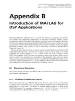
MorphoSys is one of the few coarse-grain reconfigurable platforms. Fig. 1 shows the block
diagram and internal structure of MorphoSys M1 chip and the logic block for each
reconfigurable cell. MorphoSys consists of two main blocks: a RISC processor, TinyRISC,
and the Reconfigurable Cell (RC) Array. The other supporting blocks are: the RC context
memory, the frame buffer, and the DMA controller. The frame buffer as well as the context
memory provides the data and instructions, respectively, in parallel fashion to the RC Array
(Lee et al., 2000).
The computing power of the MorphoSys hardware lies in the reconfigurable device. It is
divided into four quadrants. Fig. 2 shows the internal interconnectivity of the RC system
(Lee et al., 2000). As shown, three hierarchical levels define the interconnection meshwork.
The first is a layer that connects each cell to its adjacent cell, i.e. upper, lower, and left cells.
The second is an intra-quadrant connection that connects the RCs in the same row or
column within the same quadrant. The third level of connectivity is an inter-quadrant
connection that links any two cells in different quadrant but in the same column or in the
same row. Fig. 1 also shows the RC block diagram. It consists of multiplexers, ALU, four
registers, variable shifter, and output register. The inputs for every RC are from the frame
buffer, other RCs, and internal Registers (Singh et al., 1998).
Figure 1. MorphoSys Block Diagram and RC Logic Digaram
Data Acquisition Applications
6
Figure 2. RC Array Communication Buses
4. Cryptographic algorithms mapping onto MorphoSys
Cryptography has grown to be a fundamental element to handle authenticity, integrity,
confidentiality and non-reputability of private data flows through public networks. With the
increasing demand for high performance hardware, and high level of security, better ciphers
are making their way to replace aging algorithms that have proven to be too weak or too
slow for the current applications (Schneier, 1996). In this section, we discuss the mapping of
the Rijndeal and Twofish encryption algorithms.
4.1. Rijndael encryption algorithm
The Advanced Encryption Standard, AES, is a block cipher adopted as an encryption
standard by the National Institute of Standards and Technology, NIST, in November 2001
after a five-year standardization process. The block diagram of the Rijndael algorithm is
shown in Fig. 3. The figure shows the steps for both encryption and decryption cases
(Daemen & Rijmen, 2002).
4.1.1. Rijndael rounds
First, the input bits are arranged according to the length of the plain text to be encrypted. In
the case of 128 bit length, the bits are arranged as 44 matrix of bytes; for 192, it will be 46
matrix of bytes; and for 256, it will be 48 matrix of bytes. The numbers 4, 6, and 8 are called
the block width, N
b
. The keys of the cipher are also arranged in the same fashion (Daemen &
Rijmen, 2002).
Rijndael has three different types of Rounds; as shown in Fig. 3:
i. The first is the Initial Round. It is, as shown in equation (1), performed by XORing the
input Plain Text matrix with a predefined Key. This process called Add-Round-Key.
Reconfigurable Systems for Cryptography and Multimedia Applications
7
BAK
(1)
where B (size 4 by N
b) is the output byte matrix, A (size 4 by Nb) is the input byte matrix and
K (size 4 by N
b) is the Key byte matrix.
Figure 3. The Rijndael Algorithm (Daemen & Rijmen, 2002).
ii. The second is the Standard Round. In the Standard Round four different steps are
performed:
a. Sub-Bytes: this is a simple byte substitution using a predefined lookup table. Two tables
are used, one for encryption and another for decryption.
b. Shift-Row: this step is performed through shifting and rotating the bytes in each row of
the input matrix in a predefined manner. The shifting offset is defined according to the
block width N
b. The bytes will be shifted, then, rotated repeatedly.
c. Mix-Column: the columns are mixed through a matrix multiplication of the plain text by
a predefined matrix, given by the authors of the Rijndael algorithm (Daemen & Rijmen,
2002), over Galois Field with an irreducible polynomial 100011011. In the decryption
case, this step is referred to as Inverse Mix-Column or InvMix-Column.
Some mathematical simplification is carried out in order to reduce the multiplication
computation. In the encryption case the multiplication is performed as shown in equation
(2). Note that the multiplication operator is shown as to indicate that the multiplication is
over Galois Field (Daemen & Rijmen, 2002).
Data Acquisition Applications
8
00 07 00 07
10 17 10 17
20 27 20 27
30 37 30 37
02 03 01 01
01 02 03 01
01 01 02 03
03 01 01 02
BB AA
BB AA
BB AA
BB AA
(2)
The matrix used in the multiplication during the Inverse Mix-Column (InvMix-Column) step
is shown in equation (3). This multiplication is also carried over Galois Field with the
irreducible polynomial 100011011 (Daemen & Rijmen, 2002).
00 07 00 07
10 17 10 17
20 27 20 27
30 37 30 37
000 09
09 0 0 0
00900
0 0 09 0
BB AA
EBD
BB AA
EBD
BB AA
DEB
BB AA
BD E
(3)
a. Add-Round-key: is XORing each byte with a predefined key.
Rijndael has a variable number of iterations, N
i, for the Standard Round:
N
i = 9, where Nr = Number of rounds = 10, if both the block and the key are 128 bits long.
N
i = 11, where Nr = 12, if either the block or the key is 192 bits long, and neither of them
is longer than that.
Ni = 13, where Nr = 14, if either the block or the key is 256 bits long.
Table 1. shows the key size, block width N
b and the corresponding Nr.
Key Size
128 192 256
Nb 4 6 8
Nr 9 11 13
Table 1. Key Size, Block Width Nb and Round Number Nr, (Daemen & Rijmen, 2002)
i. The third type of round is called the Final Round. In the Final Round only three of the
four steps, mentioned in the Standard Round, are performed excluding the Mix-
Column step.
During decryption, all the steps are preformed in reversed order (Daemen & Rijmen, 2002).
4.1.2. The key schedule for Rijndael
The Round-Keys are derived from the original Cipher Key by means of the Key Schedule.
The algorithm to generate the key is shown in Fig. 4. The original key provided is 128, 192 or
256 bits. The key should be arranged in a 4Nb Matrix. As discussed in the previous section,
the Add-Round-Key step is performed once in the First Round, N
r-1 times in the Standard
Round, and once again in the Final Round. In total, Nr+1 Round-Key matrices are needed to
cover all the rounds.
Reconfigurable Systems for Cryptography and Multimedia Applications
9
The first Round-Key is given, as shown in equation (4), however, the remaining, N
r
, Round-
Key matrices are generated (Daemen & Rijmen, 2002). For example, for a block length of 128
bits, 10 Round-Keys matrices are needed: 9 for the Standard Rounds and 1 for the Final
Round. For block length of 192 bits, 12 Round-Keys are needed and for 256 bits length 14 are
needed.
01 01
00 00
11 11
10 10
01
20 20
21 21
30 30
31 31
;
bb
bb
b
bb
bb
NN
NN
N
NN
NN
kk
kk
kk
kk
KKK
kk
kk
kk
kk
(4)
Figure 4. Generating key schedule for Rijndael (Daemen & Rijmen, 2002).
Then the remaining keys are generated (Daemen & Rijmen, 2002). Fig. 4 shows the key
schedule algorithm, where i denotes the column number, iterating from 0 to N
b
-1. The
function S
1
(K
i-1
) is a cyclic shift of the elements in K
i-1
. For example, if K
i-1
column is [k
0x
, k
1x
,
k
2x
, k
3x
], then S
1
(K
i-1
) is [k
1x
, k
2x
, k
3x
, k
0x
].
The rcon function is a round-dependent constant XORed to the first byte of each column
(Daemen & Rijmen, 2002). These round constants are calculated offline. It is the successive
powers of 2 in the representation of GF(2^8) (Daemen & Rijmen, 2002). The Key is saved in
the memory to be XORed during the encryption or decryption.
4.1.3. Rijndeal performance analysis
In this section, the performance results are presented. Some of the bottleneck problems are
discussed, and possible solutions are proposed (Majzoub et al., 2006). Fig. 5(a) shows the
time cost of the four steps done in one iteration of the Standard Round. The figure shows the
Data Acquisition Applications
10
encryption and the decryption costs for all the key length cases. Clearly, the Sub-Bytes step,
or the lookup table step, is dominating the computation time. The Sub-Bytes step is taking
83% of the total Round cost in the best case and 97% in the worst case. The next bottleneck is
the Mix-Column and InvMix-Column step. Both InvMix-Column and Mix-Column steps are
taking 2% in the best case and 16% in the worst case.
(a) (b)
Figure 5. Time cost breakdown, (a) Encryption and Decryption, and (b) Inverse-Key (Inv-Key)
Schedule.
Fig. 5(b) shows the time cost of the Inverse Key Schedule performance results. Again, the
Sub-Bytes and the InvMix-Column are the major bottlenecks. The Sub-Bytes is taking 60% in
the best case and 74% in the worst case. The InvMix-Column is taking 22% in the best case
and 35% in the worst case.
Fig. 6 shows the RC Utilization during the encryption and decryption respectively. The
figure shows the RC utilization for one iteration of the Standard Round. It is clear the 8×8
RC Array is fully utilized during the lookup table and partially utilized, but with high rate,
during the Mix-Column and InvMix-Column.
As shown in Fig. 6, there are 4 lookups in case of 256 covering the 4 rows. In the 192 case,
there are 3 lookups to cover the 3 rows and in the case of 128 there are 2. During every
lookup there is a full utilization and then a small stall when switching from one row to
another. At the end of lookup step, the Mix-Column step starts. The Mix-Column utilizes
half the RC Array in the 192 and 256 cases and quarter of the RC Array in the 128 case. The
InvMix-Column almost utilizes the whole RC. In the utilization image, seem the lookup
table and the InvMix-Column still dominates the major bottlenecks.
Reconfigurable Systems for Cryptography and Multimedia Applications
11
Figure 6. RC Utilization, Encryption and Decryption (Standard Round)
Figure 7. RC Utilization, Key and Inverse Key Schedule (One Round-Key)
Fig. 7 shows the RC Utilization during the Key Schedule. The lookup table steps are
utilizing half of the RC Array in the 256 and 192 cases. However, it utilizes the whole RC
Array in the case of 128, this is because it is doing a redundant lookup on the other half to
save few cycles. This can be changed to be like the 192 and 256 cases, especially if two keys
need to be processed at a time. This way we can double the throughput in the cost of few
cycles, which is better implementation anyway. The Inverse key shows the same results the
key with the addition of the InvMix-Column. In the InvMix-Column case the utilization is a
bit high. This is because the column mixing should be done for all the columns not for one
like the case of the lookup.
As all the figures and analysis showed, the lookup table is the major bottleneck in terms of
both RC utilization and time consuming. In order to improve the Rijndael on MorphoSys,
the first idea to think of is implanting a lookup table. A good implementation of a lookup
table in the system can improve the Rijndael performance tremendously. Although the
InvMix-Column is of specific nature, there are still some improvements that can be
proposed. Further work could be by implementing new bit wise instructions. Moreover,
better results can be achieved also by implementing a second level of RC-Instruction level
parallelism.
Fig. 8 shows the RC instruction utilization. These results are for one iteration of the Standard
Round for the three cases: 128, 192 and 256. The CMULBADD instruction is basically
Data Acquisition Applications
12
multiplying MUX_A input by the constant C and adding the result to MUX_B. The SR and
SL are shifting to the right and left respectively. The analysis in these figures can clarify the
importance of some of the instructions. The XOR, BTM, ADD, and SR are the most
instructions utilized during the process (Singh et al., 1998). Note that the BTM instruction is
a bit-wise instruction that counts the number of ones in a byte.
Figure 8. RC-Instruction Utilization, 128 and 192, and 256 cases (One Round)
It should be mentioned here that if the lookup table, the most extensive operation, is
replaced by other means then this figure might change dramatically. One improvement
could be by adding a parallelism at the RC instruction level. For instance, The XORing will
have three operands instead of two. This reduces the XORing utilization by one third.
Similar improvements can be done in the same fashion for the other instructions.
The fourth plot in Fig. 8 shows the RC instruction utilization in the major steps. This figure
clearly shows that if there is any further investigation, it should be in the lookup table and
the InvMix-Column. Better implementation of the BTM instruction improves the results
(Singh et al., 1998). For instance, implementing a similar BTM instruction but with XORing
all the output instead of counting all the ones eliminates 8 cycles of the computation of every
byte. We will elaborate on this issue later.
Fig. 9 shows the final performance results for both the encryption and the decryption for the
three plain text length cases. It shows also the performance results of the Key Schedule for
the three plain text length cases.
Reconfigurable Systems for Cryptography and Multimedia Applications
13
Tables 2 and 3 show the performance results of the MorphoSys compared to the platforms
submitted with the Rijndael proposal to the NIST (Daemen & Rijmen, 2002).
Figure 9. Rijndeal Performance Results
Key
Size
AES CD
(ANSI C)
Brain
Gladman
(VC++)
MorphoSys
Key InvKey Key InvKey Key InvKey
128 2100 2900 305 1389 1040 1223
192 2600 3600 277 1595 1224 1829
256 2800 3800 374 1960 2758 3473
Table 2. Key Schedule compared to other platforms showing number of cycles, (Daemen & Rijmen,
2002).
Key
Size
Intel
8051
Motorola
68HC08
AES CD
(ANSI C)
Brain
Gladman
(VC++)
Java
MorphoSys
En/Dc
128 4065 8390 950 363 23000 2021/2236
192 4512 10780 1125 432 27600 3546/4041
256 5221 12490 1295 500 32300 5426/6010
Table 3. Performance results for Encryption/Decryption compared to other platforms, showing
number of cycles, (Daemen & Rijmen, 2002).
The MorphoSys shows acceptable results compared these platforms. However, and since the
proposal submission, there were many implementations on FPGAs and ASIC platforms
(Sklaos & Koufopavlou, 2002). These implementations showed a throughput that
MorphoSys cannot compete with. For instance, the throughput ranged from 248 up to 3650
MBps which is very high throughput compared to our results. In contrast, the MorphoSys
platform is much more flexible than the ASIC or FPGA. A wide range of applications can be
implemented on MorphoSys, taking advantage of the fact that MorphoSys is a low power
consumption platform (Majzoub & Diab, 2006). Saying all this, still the MorphoSys can and
should be improved in order to compete with other platforms.
Data Acquisition Applications
14
4.2. Twofish encryption algorithm
In this section, the Twofish cipher, one of the five finalists considered in the advanced
encryption standard (AES) competition is implemented on MorphoSys. Twofish is a 128-bit
cipher that supports keys with length of 128-, 192- or 256-bits. It is the successor of Blowfish,
a well-established cipher without any known flaws (Schneier et al., 1998). The Twofish
cipher has many qualities that make it interesting for a research. It has been designed to
offer different possibilities of trade-offs between space and speed, thus it can be mapped
efficiently to hardware devices such as FPGAs, SmartCards and RCs (Majzoub & Diab,
2003), (Schneier 1996).
Fig. 10 shows the overall structure of the Twofish algorithm. As shown, the input is first
latched into a register. It is then separated into four words and XORed with four subkeys
K
0,K1,K2 and K3. This step is referred to as the input whitening. The data then goes through a
F-function module where various rotations, transformations and permutations are applied.
The F-function is made of two g-functions containing key-dependant S-boxes, a Maximum
Distance Separable (MDS), (Schneier et al., 1998), matrices and a Pseudo-Hadamard
Transform (PHT), (Schneier et al., 1998); all of which will be described later. After
performing 16 rounds of the F-function, the four data words are once again XORed with
another four subkeys K
4, K5, K6 and K7 to produce the cipher text. This step is called the
output whitening (Schneier et al., 1998).
4.2.1. Twofish phases
In this section, we explain the mapping details of the Twofish algorithm on MorphoSys
platform. The computationally expensive operations, such as the S-box, MDS and PHT, are
performed in the reconfigurable part of the MorphoSys. While the other operations, for
instance data loading and saving operations are executed in the TinyRISC processor. Fig. 10
shows the overall steps of the Twofish algorithm.
The Twofish steps are as following:
a. Input Whitening: the plain text input, P
0,P1,P2, and P3, are XORed with the whitening
keys i.e.: P
0 K0; P1 K1; P2 K2; and P3 K3.
b. S-Box Computations: The S-box is a phase in which a lookup table is used. The inputs are
substituted by data with the same number of bits from a predefined lookup table.
c. MDS Matrix Multiplication: the input data is multiplied by a predefined matrix over
Galois field with irreducible polynomial 101101001.
d. PHT Computations: The PHT, (Pseudo-Hadamard Transforms), as stated before, is the
calculation of the following equations:
32 32
001 10 1
mod2 ; 2 mod2PPP PP P
(5)
where P
0 and P1 are 32 bit each, the first one in the first four columns and the second is in the
second four columns of the RC Array.
0
P
and
1
P
are the expected results of these two
equations.
Reconfigurable Systems for Cryptography and Multimedia Applications
15
Figure 10. Overall Structure of Twofish Algorithm
a. XOR with k-Subkeys: This operation can be done either by adding or XORing. In our
implementation, we used XORing as it is faster.
b.
XORing with P2 and P3: the result should be XORed with P2 and P3. Then, a rotation to
the left or to the right by one bit is performed after or before the XORing. The first
block, i.e. P
0, is XORed with P2 and then rotated by one bit to the right. The next one, i.e.
P
1, is XORed with P3, and then rotated by one bit to the left.
c.
Output Whitening: This phase is exactly the same as the input-whitening step, which is
basically XORing with output subkeys.
4.2.2. The key schedule for Twofish
The key schedule has to provide 40 words of expanded key K0 ,…, K39. Twofish is defined
for keys of length N = 128, N = 192, and N = 256. A constant k is defined as k = N/64. Key
generation begins by deriving three key vectors each half the length of the original key
(Schneier et al., 1998). The first two are formed by splitting the key into 32-bit parts. These
parts are numbered starting from zero, the even-numbered are M
e, and the odd-numbered
are M
o. This can be expressed by equation (6).
3
8
(4 )
0
.2 0, ,2 1
j
iij
j
Mm i k
(6)
The first two vectors are M
e=(M0,M2,…,M2k-2) and Mo=(M1,M3,…,M2k-1). The calculation of the
vectors M
o and Me are straightforward. We just have to separate the odd bytes from the even
ones. Afterwards the expanded key words should be derived from M
e and Mo and stored in
F
P
(
128 bits
)
C
(
128 bits
)
Input Whitening
Output Whitening
15 more rounds
S-
b
ox 0
S-
b
ox 1
S-
b
ox 2
S-
b
ox 3
MDS
g
S-
b
ox 0
S-
b
ox 1
S-
b
ox 2
S-
b
ox 3
MDS
g
<<<8
PHT
<<<1
One round operation
k
k
>>>1
Data Acquisition Applications
16
the memory to be used later. The key computations are performed offline and then stored in
main memory to be used later in the encryption.
The key scheduling operation is shown in Fig. 11. Initially, 2i and 2i+1 words are passed to
the S-Boxes so that the M vector is initially XORed with values represent S(2i) or S(2i+1).
This is because the 2i and 2i+1 values are predefined and do not change with different key
values. For each expanded key word the vector M
e or Mo is XORed with a number taken
from the frame buffer represents S(2i) or S(2i+1). The RC instructions used to calculate the h-
function in the context memory are the same ones used to calculate F function with some
modifications. Some additional planes in context memory are used to resolve the difference
in the h- and g-functions. Before the PHT step, the word k
2i+1 is rotated 8 bits to the left.
Figure 11. Key Schedule for Twofish
Afterwards, the PHT is performed. Then, the last four bytes are rotated by nine bits. The
final result is transferred to the cell in the first row. The content is then loaded from this cell
to the registers in the TinyRISC using RCRISC instruction.
In the case of 256 bits, there are eight bytes. In the case of the 192 bits, there are three bytes
in each vector. Finally, in the case of the 128, there are 2 bytes in each vector. As stated
before, the odd bytes should be separated from the even ones. Each vector has four bytes.
On the other hand, the S vector is derived through multiplying the Key K (256, 192, or 128
bits) by the RS matrix. The key K is divided into 8 bytes groups and multiplied by the RS
matrix as shown in equation (7).
8
81
,0
82
,1
83
84
,2
85
,3
86
87
01 4 55 87 5 58 9
456 82 31 6 68 5
.
02 1 1 47 3 19
455875 58 9 03
i
i
i
i
i
i
i
i
i
i
i
i
m
m
s
m
AADBE
s
m
AFECE
m
sAFCCAED
m
AADBE
s
m
m
(7)
K
2i
K
2i+1
MDS
M
2
M
0
h
2i
2i
2i
2i
MDS
M
3
M
1
h
2i+1
2i+1
2i+1
2i+1
<<8 <<9
PHT