PELLPACK: A Problem Solving Environment for PDE Based Applications on Multicomputer Platforms docx
Bạn đang xem bản rút gọn của tài liệu. Xem và tải ngay bản đầy đủ của tài liệu tại đây (784.13 KB, 36 trang )
June 11, 1997 1
PELLPACK: A Problem Solving Environment for PDE Based
Applications on Multicomputer Platforms
E. N. Houstis, J. R. Rice, S. Weerawarana, A. C. Catlin,
P. Papachiou, K Y. Wang and M. Gaitatzes
ABSTRACT
This paper presents the software architecture and implementation of the problem solving
environment (PSE) PELLPACK for modeling physical objects described by partial differ-
ential equations (PDEs). The scope of this PSE is broad as PELLPACK incorporates many
PDE solving systems and some of these, in turn, include several specific PDE solving
methods. Its coverage for 1-D, 2-D and 3-D elliptic or parabolic problems is quite broad,
and it handles some hyperbolic problems. Since a PSE should provide complete support
for the problem solving process, PELLPACK also contains a large amount of code to sup-
port graphical user interfaces, analytic tools, user help, domain or mesh partitioning,
machine and data selection, visualization, and various other tasks. Its total size is well over
1 million lines of code. Its open-ended software architecture consists of several software
layers. The top layer is an interactive graphical interface for specifying the PDE model
and its solution framework. This interface saves the results of the user specification in the
form of a very high level PDE language which is an alternative interface to the PELL-
PACK system. This language also allows a user to specify the PDE problem and its solu-
tion framework textually in a natural form. The PELLPACK language preprocessor
generates a Fortran control program with the interfaces, calls to specified components and
libraries of the PDE solution framework, and functions defining the PDE problem. The
PELLPACK program execution is supported by a high level tool where the virtual parallel
system is defined, where the execution mode, file system, and hardware resources are
selected, and where the compilation, loading, and execution are controlled. Finally, the
PELLPACK PSE integrates several PDE libraries and PDE systems available in the public
domain. The system employs several parallel reuse methodologies based on the decompo-
sition of discrete geometric data to map sparse PDE computations to parallel machines.
An instance of the system is available as a Web server (WebPELLPACK) for public use at
the .
keywords: domain decomposition, expert systems, framework, knowledge bases, parallel
reuse methodologies, parallel solvers, problem solving environments, programming-in-
the-large, programming frameworks, software bus.
1. INTRODUCTION
The concept of a mathematical software library was introduced in the early 70s [41] to support the reuse of high qual-
ity software. In addition, special journals, conferences, public domain software repositories (e.g., ACM, Netlib), and
commercial libraries (i.e., IMSL, NAG) have been established to support this concept. Similar efforts can be found in
engineering software, particularly in the areas of structural and fluid mechanics. The increasing number, size, and
complexity of mathematical software libraries necessitated the development of a classification and indexing of exist-
ing and future software modules. This software is currently organized in terms of the mathematical models involved.
A significant effort in this direction is the GAMS on-line catalog and advisory system [5] which has become a stan-
dard framework for indexing mathematical software. Information about engineering software can be found in several
handbooks which usually describe the applicability and functionality of existing packages. The advances in desktop
software/hardware, workstation clustering and distributed computing technologies, and the ease of access to super-
computing facilities have made computational prototyping a new, cost effective alternative for the design of new
products and for the study of science and engineering phenomena in general. Although the software library provides
June 11, 1997 2
some form of abstraction and a facility of reusing software parts, it still requires a level of computing expertise above
the background and skills of the average scientist and engineer who usually design manufactured products. This rec-
ognition has lead to the new concept of software reuse referred throughout as Problem Solving Environment (PSE).
The current PSEs consist of small sets of modules, usually taken from existing libraries, integrated (packaged) to han-
dle a predefined class of mathematical models. In these PSEs the specification of the mathematical model, the prob-
lem solving process, and the required pre-processing or post-processing phases are done with a high level user
interface. This interface usually consists of a very high level language and graphical interface that allows the user to
specify the problem and visualize the solution in some “natural” form. Early examples of PSEs are Macsyma, Mathe-
matica, Maple, ELLPACK, MatLab, and several engineering software systems. Similar software evolution can be
observed in the pre-processing (CAD, mesh generation) and post-processing (data visualization) tools. These PSEs
and the associated pre- and post-processing tools have greatly increased the abstraction of computational prototyping
for some applications. As a result users with minimum computational background can be engaged in the prototyping
of complex artifacts. PSEs are distinguished with respect to the domain of problems or applications they can handle.
An important distinction between a PSE and a monolithic software system is that PSE's have a flexible and extensible
architecture that is easy for a user to tailor or a builder to enhance. The software architecture of PSEs is characterized
by the integration model used to connect the software parts involved and the underlying execution model
assumed.The common shortcoming of current PSEs is that the knowledge associated with the library, the applicabil-
ity, compatibility, and performance (i.e. complexity) of library modules, the selection of the computational parame-
ters, error estimation, etc. is not part of the PSE but is part of the responsibility of the user. One can argue that the
ideal PSE should make decisions to help the user by consulting a knowledge base about the user, the problem domain,
and past solutions of similar problems. This leads us to the following formal definition of a PSE:
PSE = User interface + libraries + knowledge base + software bus.
In this paper we describe the architecture and functionality of a PSE called PELLPACK for solving certain classes of
partial differential equations (PDEs) on sequential and multicomputer platforms. It is a descendent of ELLPACK [40]
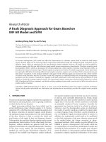
which allows users to solve PDEs for linear and nonlinear field and flow problems. Figure 1 depicts a user’s view of
the PELLPACK system in terms of the tools and libraries needed to specify and solve a PDE problem on a target
computational platform and to visualize the solution. Figure 1 is further illustrated by a PDE solving scenario in sec-
tion 2.4.2. PELLPACK provides an interactive graphical user interface for specifying the PDE model, its solution
method and post-processing, supported by the Maxima symbolic system and well known libraries. In addition, it pro-
vides an intermediate high level facility for composing new algorithms from existing parts and it supports a program-
ming-in-the large environment with a language which is an extension of the ELLPACK language [40]. The user
interface and programming environment of PELLPACK is independent of the target machine architecture and its
native programming environment. PELLPACK is supported by a library of parallel PDE modules for the numerical
solution of stationary and time dependent single equation PDE models on two and three dimensional regions. A num-
ber of well known “foreign” PDE systems have been integrated into PELLPACK which are listed in Table 1. PELL-
PACK can simulate structural mechanics, semi-conductors, heat transfer, flow, electromagnetic, microelectronics, and
many other scientific and engineering phenomena. Five different implementation languages have been used to build
the system. The current size of PELLPACK is 1,900,000 lines of code. The parallel codes of PELLPACK currently
use the PICL, PARMACS 5.1, MPI, PVM, NX and Vertex communication libraries. The size of the parallel library is
128,000 lines of Fortran code for each implementation and consists of finite element and difference modules for dis-
cretizating elliptic PDEs, a parallelization of the ITPACK library [28], [30], [32] and the MP-PCG (parallel precondi-
tioning conjugate gradient) package [44]. The parallel library is based on the discrete domain decomposition
approach and it is implemented in both the host-node and hostless programming paradigms. A number of tools and
libraries exist to support the domain decomposition methodology and estimate (specify) its parameters. For the reuse
of existing “legacy” sequential PDE software we have implemented two domain decomposition based reuse method-
ologies described in [33].
The paper is organized in nine sections. Section 2 describes the exact applicability of the system in terms of the exist-
ing PDE libraries and pre-defined frameworks. We list several standard solution frameworks for various PDE models,
and we describe the frameworks needed to use one of the integrated “foreign” systems. In addition we describe paral-
lel re-use frameworks for steady-state PDE software. The multi-level PELLPACK architecture is discussed in Section
3, and Section 4 describes the three level programming environment. The PELLPACK PSE allows the user to execute
June 11, 1997 3
programs in a variety of physical and virtual parallel architectures. Section 5 describes a visual scripting execution
environment that allows the user to select the computers and to direct the running of computations and the visualizing
of results. Section 6 describes an expert system methodology that can be used to implement the adaptability of the
system to user’s expertise and computational objectives. This methodology and its software has been implemented
and tested in the context of the ELLPACK library [25] whose highlights are presented in Section 6. Section 7 presents
two scenarios that demonstrate the PELLPACK design objective of reuse of high quality mathematical software, the
facility for development of new PDE software, and the integration of “foreign” software. The future scenario for
usage and maintenance of high quality mathematical software calls for remote “net-centered” servers and networked
software that will allows users to compute over the “network” as they compute in the world of front-end workstation
to an intranet computer system. We have created a Web server for PELLPACK that allow users to experiment with the
system and get answers, instead of downloading software and addressing issues of local installation, maintenance,
and licensing. This server and its accessibility is described in Section 8 and its Web location is -
due.edu.
FIGURE 1. A user’s view of the PELLPACK system depicting the tools and libraries
supported. The diagram is organized in terms of the four solution phases involved in
PDE computing: problem specification, solution specification, problem execution,
and solution post-processing.
PDE ProblemPDE SolutionExecution
Post-processing
MAXIMA
System
Symbolic
Environment Environment Specification Specification
PDE
Specification
Framework
Boundary
Editors
Conditions
Geometry
Editors
Machine
Facilities
Configuration
Initial
Editors
Conditions
Geometry
Decomposers
Geometry
Discretizers
Algorithm
Editors
Output
Specification
Knowledge
Bases
S
o
f
t
w
a
r
e
b
u
s
i
n
t
e
r
f
a
c
e
E
L
L
P
A
C
K
S
E
S
S
I
O
N
Language
Processor
Execute
Tool
Performance
Tools
Analysis
Visualization
Tools
Data Analysis
Tools
Output
Tool
Foreign
Libraries
Solver
//ELLACK
Libraries
Solver
P
June 11, 1997 4
This work is the result of a significantly large group of people and the support of many government and industrial
organizations listed in alphabetical order in Section 9.
2. DOMAIN OF APPLICABILITY
The applicability of the PELLPACK system is defined in terms of the types of PDE software libraries integrated into
the system, and the pre-defined algorithm skeletons and frameworks directly supported at the PELLPACK very high
language and graphical user interface levels. An algorithm skeleton is a “solution driver”, i.e., a specification of the
methods which are to be used in the solution of a PDE problem. A PELLPACK framework is a customized solution
driver, requiring a specialized form of PDE problem and solution specification. The form of this specification is deter-
mined by the user-selected PDE software library to be used in the solution process. The framework includes the
solver system selection, the mathematical representation of the PDE model (which often depends upon the selected
solver), and the interfaces between the solver library and the PELLPACK runtime system. Most frameworks in PEL-
LACK handle general (systems of) PDEs. A PELLPACK template is a framework for a specific PDE model, such as
the Navier-Stokes equations. The PDE specification in this case is a set of parameter values.
2.1 PDE SOFTWARE LIBRARIES
The PDE libraries currently integrated in PELLPACK are listed in Table 1. They allow the numerical solution of field
and flow PDE problems in various geometric regions. The integration of these simulation libraries is done at the PDE
language, graphical interface, and data interface levels. The PELLPACK programming environment allows differen-
tial, variational, and template forms for specifying the PDE and auxiliary operators. The PELLPACK PDE problem
specification and its “derivatives” (i.e., Jacobian, linearization transformations, forcing functions) are computed and
converted symbolically to the pre-defined Fortran interface format assumed by the selected PDE library. The 3-D
PDE domain geometry can be specified only in terms of files in well established geometry data formats (e.g., polyfile)
that PELLPACK recognizes. The system provides a 2-D geometry specification tool.
TABLE 1. PDE systems integrated in PELLPACK, their applicability, and major characteristics
Solver Name PDE Model Type Mathematical Representa-
tion and Mesh Restrictions
Dimensionality
and Geometry
References
ELLPACK single elliptic
equation
Differential
e.g.
2-D general,
3-D box geometry
[40]
PELLPACK single elliptic
equation
Differential 2-D and 3-D
general geometry
[21], [22],
[23], [29],
[57]
VECFEM non-linear, elliptic,
parabolic systems,
eigenvalue
problems
Variational
e.g.
1-D, 2-D, 3-D
general geometry
[17]
FIDSOL nonlinear, elliptic,
parabolic systems
Differential 2-D and 3-D
box geometry
[43]
CADSOL nonlinear, elliptic,
parabolic systems
Differential 2-D general geometry [42]
PDECOL nonlinear, parabolic
systems
Differential 1-D interval [31]
uxx uyy+
f=
u
x
v
x
u
y
v
y
+
(
) ωd
Ω
∫
fv ωd
Ω
∫
=
June 11, 1997 5
2.2 FRAMEWORKS FOR PELLPACK PDE SOLVERS
The design of the PELLPACK programming environment (i.e., a very high level PDE language and interactive edit-
ing tools) has been influenced by the requirements of its current solving capabilities and the structure of the solution
skeletons (i.e., drivers) that the user is allowed to specify and run. Other solution frameworks, can be easily created in
the PELLPACK system by utilizing the pre-defined fixed interfaces among the PDE solution phases, existing or new
PDE software parts, and Fortran code. For example, the parallel time-stepping methodology described in [53] has
been implemented in PELLPACK utilizing a variety of PELLPACK iterative solvers and its performance was mea-
sured on a variety of platforms [48]. In this section we describe the various pre-defined solution frameworks that
PELLPACK currently supports.
2.2.1 ELLIPTIC AND PARABOLIC PDE SOLUTION FRAMEWORKS
PELLPACK allows the solution of single linear and non-linear elliptic and parabolic PDE equations defined on 2-D
and 3-D domains. In this framework, the user can specify a solution method by naming (referencing) selected library
modules (discretization, indexing, solution) corresponding to the phases of the PDE solution pro-
cess [40] (see Figure 2 for an example). In the case of coupled or single-phase solvers the name of the triple mod-
ule is specified. Framework 1 below lists the segments of this framework. The parallel elliptic framework currently
supported in PELLPACK is based on geometric partitioning of the grid or mesh data. Thus, the user is required to
specify the decomposition data in the form of a file with appropriate format and parameters. This segment can be gen-
erated by an interactive editor which allows the visualization and editing of mesh/grid decomposition data and uses a
library of semi-optimal partitioning algorithms for their automatic generation [7], [9], [54]. In the case of parallel
elliptic solvers, the parallel versions of the library modules specified have been implemented using several virtual
(e.g., PVM, MPI) and machine native (e.g., Vertex, NX) communication libraries [28],[29],[32].
FRAMEWORK 1. Module based linear elliptic solution
ITGFS 2-D Navier-Stokes Template,
structured meshes
e.g. transonic turbulence flow
parameter values
2-D general geometry [57]
NSC2KE 2-D Navier-Stokes Template,
structured meshes
2-D general geometry [3]
NPARC3-D 3-D Navier-Stokes Template,
multi-block structured meshes
3-D general geometry [10]
PDEONE nonlinear, parabolic
systems
Differential 1-D interval [19]
Segment Description Options
Declarations, Options Space for saving solution, parallel machine configuration
and model
sequential, parallel
Equation, BCs PDE problem definition differential
Grid/Mesh Domain discretization sequential, parallel
Decomposition Grid/Mesh partitioning file needed for the parallel solution sequential, parallel
Multi-phase PDE solver
Discretization PDE problem discretization sequential, parallel
TABLE 1. PDE systems integrated in PELLPACK, their applicability, and major characteristics
June 11, 1997 6
For non-linear elliptic PDEs, a linearization procedure is applied at the continuous PDE problem level which is
described in [51]. This framework is generated symbolically using the Maxima-based PDE framework specification
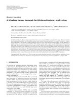
editor of the PELLPACK graphical interface, which is described in Section 4.2. Framework 2 describes the segments
of this framework.
FIGURE 2. An instance of PELLPACK user interface for an elliptic framework
Indexing Discrete equations ordering scheme sequential, parallel
Solution Linear solver sequential, parallel
Single-phase PDE solver
Triple Integrated discretization, indexing, solution phases sequential
Output Format for solution output
FRAMEWORK 2. Nonlinear sequential elliptic PDE solution
Segment Description
Declarations, Options Space for saving solution(s)
Equation, BCs PDE problem definition
Grid/Mesh Domain discretization
Triple Initial guess
Fortran Newton loop start
Linearized Elliptic Solver Elliptic problem discretization, indexing, solution
June 11, 1997 7
Similarly, there is a framework for implementing semi-discrete parabolic PDE solvers which utilizes the available
PELLPACK elliptic PDE solvers. In this case users can select pre-defined time discretization schemes or specify their
own and reduce the parabolic PDE problem to a set of elliptic PDEs defined at each time-step. The framework for
these solvers is described in Framework 3 and [51].
2.2.2 MPLUS (MATRIX PARTITIONING) STEADY-STATE SOLUTION FRAMEWORK
This framework is applicable to any non-time dependent PDE computation and is designed to re-use existing sequen-
tial PDE discretization software in a parallel solution scheme. It assumes that the discrete equations are generated
sequentially with any of the existing libraries. It uses mesh/grid decomposition data or user defined partitions for the
algebraic data structures associated with the selected PDE solver. The partitioned discrete PDE (i.e., algebraic) equa-
tions are loaded into the targeted multicomputer platform and solved in parallel by the available parallel solvers.
Framework 4 displays the skeleton of this framework. The methodology and its performance evaluation described in
[33].
FRAMEWORK 4. Parallel matrix solution
Output Format for solution output
Fortran Convergence test
Fortran Newton loop end
Subprograms Initial guess, Jacobian and other support functions
FRAMEWORK 3. Parabolic sequential PDE solution
Segment Description
Declarations, Options Space for saving solution(s)
Equation, BCs PDE problem definition
Grid/Mesh Domain discretization
Triple Initial condition
Fortran Time stepping loop start
Elliptic PDE solver Elliptic problem discretization, indexing, solution
Output Format for solution output
Fortran Convergence test
Fortran Time stepping loop end
Subprograms Initial condition and other support functions
Segment Description
Sequential solution
framework
The PDE problem, its discretization, and sequential solver
Partition Discrete geometric or user defined algebraic data partitioning strategy
Load Loads partitioned algebraic system
FRAMEWORK 2. Nonlinear sequential elliptic PDE solution
June 11, 1997 8
2.2.3 DPLUS (DOMAIN PARTITIONING) STEADY-STATE SOLUTION FRAMEWORK
This framework is currently applicable to steady-state PDE models and their derivatives (i.e., implicit parabolic solv-
ers) defined on 2-D and 3-D domains. It is also based on a methodology to reuse sequential PDE discretization soft-
ware in a parallel computation [33]. It involves a decomposition of the model based on a balanced partitioning of the
PDE domain with appropriate artificial interface conditions that allow the uncoupled generation of the discrete equa-
tions in each subdomain. The decomposition of the domain is obtained via the partitioning of a relative course grid or
mesh [7]. Unlike MPlus, DPlus runs the sequential discretization code in parallel (i.e., each processor runs sequential
code on its assigned subdomain). Framework 5 lists the segments of this framework.
2.3 FRAMEWORKS FOR “FOREIGN” PDE SYSTEMS
Most general PDE solving systems require users to define PDE problems by writing Fortran functions with fixed
argument lists and data structures for the PDE equation, boundary, and initial conditions. Users write driver programs
to allocate space, initialize variables and call the solver routines with appropriate parameters and control variables.
Often, Jacobians or other symbolic computations are also required, and the results of these computations must be
written as additional Fortran functions. The functions and driver are compiled and linked with the solver library to
produce the program. PELLPACK generates these functions and drivers symbolically for the PDE solving systems of
Table 1 and the frameworks presented in the previous sections. This is the result of the integration at several PELL-
PACK levels.
A “foreign” PDE system can be integrated in PELLPACK at the PDE language level, the graphical interface level,
and the data level. Each level of integration provides a further level of abstraction by placing an additional software
interface layer between the user and the foreign system, thus simplifying the input required for defining a PDE prob-
lem. To support the language level integration, a specialized interface library is developed for each system. The inter-
face code defines the required data structures, allocates space, initializes variables, and calls the appropriate system
solver routines with appropriate values for the parameters. Users still specify the PDE problem and symbolic compu-
tations via Fortran functions that are similar (or identical) to those required by the original system, and these func-
tions are placed in the subprograms segment of the PELLPACK problem definition. Users name the solver in a
high level way and identify various high level problem characteristics such as number of equations, non-linearity, and
Display Display the structure of partitioning system
Solve Apply a parallel solver
Output Format for solution output
FRAMEWORK 5. Parallel stationary PDE solution
Segment Description
Declarations, Options Space for saving solution, parallel machine configuration and
model
Equation, BCs PDE problem definition
Mesh generation and
decomposition
Parallel multiphase mesh generation and decomposition
Interior interface condi-
tions
Interior interface BCs definition so that the generation of glo-
bal discrete equations among sub-domains is decoupled
PDE discretization Local PDE problem discretization in parallel
Solve Parallel solution of distributed discrete PDE equations
Output Format for solution output
June 11, 1997 9
time-dependence. The language integration supplies default parameter values when needed. Interface routines for all
systems generate PELLPACK format output which is used for visualization and animation of solution data with
PELLPACK’s output tool (see Section 4.3 ). The PELLPACK execution environment identifies the selected system
solver so that it can link automatically with the correct library to generate the program. The language interface simpli-
fies the specification of the PDE problem and sets the foundation for integration at the graphical level.
At the graphical interface level, users can define PDE problems using a graphical editor. To simplify the process of
specifying the PDE system, the interfaces are tailored to the representation of the equation(s) used in the selected sys-
tem. After a user enters the equations, the editor determines what symbolic manipulations are needed for defining the
problem with the selected framework, and accesses the Maxima symbolic system to perform the computations. The
editor generates the Fortran functions in the format required by the solver, and places them in the subprograms
segment. High level problem characteristics are identified symbolically, and the editor assigns appropriate values to
solver parameters. Users can later view and modify these parameters via a graphical algorithm editor. At this level of
integration, users must still be familiar with the applicability and functionality of the PDE solving system, but the
intrinsic details of problem specification are completely hidden from them.
The native data structures of the “foreign” PDE system are integrated at the Fortran level using appropriate subrou-
tines specified at the PDE language interface.
We now describe the frameworks of the integrated “foreign” PDE systems at the PELLPACK PDE language level and
depict instances of their graphical user interface.
2.3.1 VECFEM FRAMEWORK
VECFEM [17] solves non-linear, time-dependent 1-D, 2-D, and 3-D systems of equations on general domains using
mixed finite element methods. Framework 6 lists the segments of the VECFEM framework in the PELLPACK sys-
tem. Some of the PDE problem input data for VECFEM are generated by the PDE framework specification editor
(see Section 4.2.1 ). For VECFEM elliptic problems, this editor supports a variational template for specifying the
coefficients of bi-linear and linear forms and a functional template for entering the PDE in differential form. For the
stress analysis of isotropic materials, a stress template is available for entering only the elasticity modulus and Pois-
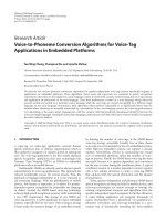
son’s number of the material. The differential form of the PDE equations is symbolically transformed to a variational
form. Figure 3 displays an instance of the PELLPACK graphical interface for VECFEM.
FIGURE 3. An instance of the PELLPACK interface for the VECFEM structural analysis framework
June 11, 1997 10
FRAMEWORK 6. VECFEM
2.3.2 FIDISOL FRAMEWORK
FIDISOL [43] solves non-linear, time-dependent 2-D and 3-D PDE systems on rectangular domains using finite dif-
ference methods. Framework 7 describes the framework for this library. Jacobians are required for the nonlinear
equations and boundary conditions; these are computed symbolically by the PDE framework specification editor.
Figure 4 displays an instance of the PELLPACK interface for FIDISOL.
FIGURE 4. An instance of the PELLPACK interface for the FIDISOL framework
FRAMEWORK 7. FIDISOL
Segment Description of language interface
Options VECFEM id, tags indicating the type of PDE (i.e., non-linear, parabolic), number
of PDE equations in the system
Equation, BCs, IC VECFEM tag for all equations indicating that the equations are defined by Fortran
subroutines in the subprogram segment
Mesh a triangular or tetrahedral mesh file generated by PELLPACK’s native mesh genera-
tors, or a neutral file generated by a “foreign” mesh generator
Triple VECFEM solver and associated parameters, output specification parameters
Subprograms Fortran functions describing the PDE equations, boundary conditions, and initial
conditions. These functions are interfaces to the functions used by VECFEM to
describe the equations.
Segment Description of language interface
Options FIDISOL id, tags indicating the type of PDE (i.e., non-linear, parabolic), number of
equations in the system
Equation, BCs, IC FIDISOL tag for all equations indicating that the equations are defined by Fortran
subroutines in the subprograms segment
Boundary 2-D, 3-D box geometry
Grid Domain discretization (uniform, non-uniform grid)
June 11, 1997 11
2.3.3 CADSOL FRAMEWORK
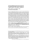
CADSOL [42] solves non-linear, time-dependent 2-D systems of equations on general domains using finite differ-
ence methods. Framework 8 describes the framework for CADSOL. The required Jacobians are computed by the
PDE framework specification editor. Figure 5 displays an instance of the PELLPACK interface for CADSOL.
FIGURE 5. An instance of the PELLPACK interface for the CADSOL framework
FRAMEWORK 8. CADSOL
Triple FIDISOL solver and associated parameter, output specification parameters
Subprograms Fortran functions describing the PDE equations, boundary conditions, initial condi-
tions. These functions are identical to the functions used by FIDISOL to describe
the equations. Functions describing the Jacobians for the PDE equations and
boundary conditions are also placed here.
Segment Description of language interface
Options CADSOL id, tags indicating the type of PDE (non-linear, parabolic), number of
equations in the system
Equation, BCs, IC CADSOL tag for all equations indicating that the equations are defined by Fortran
subroutines in the subprograms segment
Boundary domain definition (can be specified by the PELLPACK domain editor)
Mesh or Grid specify a body-oriented grid (can be generated by PELLPACK’s structured mesh
generator) or a uniform or non-uniform grid and include a user-written routine that
generates the body-oriented grid in the subprogram segment.
Triple CADSOL solver and associated parameter, output specification parameters
Subprograms Fortran functions describing the PDE equations, boundary conditions, initial condi-
tions. These functions are identical to the functions used by CADSOL to describe
the equations. Functions describing the Jacobians for the PDE equations and
boundary conditions are also placed here.
June 11, 1997 12
2.3.4 PDECOL FRAMEWORK
PDECOL [31] solves time-dependent coupled systems of 1-D non-linear equations using the method of lines. For the
space discretization a spline collocation scheme is employed. The user can select the time discretization scheme and
integration method from several options. Jacobians are symbolically generated by the PDE framework specification
editor when they are required for the problem definition.
FRAMEWORK 9. PDECOL
FIGURE 6. An instance of the PELLPACK interface for the PDECOL framework
2.4 TEMPLATES FOR “FOREIGN” PDE SYSTEMS
There are PDE systems whose mathematical model and numerical solver is specified through a set of physical and
numerical parameters (usually numerical data). These systems are usually associated with flow problems. In these
cases the PELLPACK interface consists of a hierarchical set of templates corresponding to various models the “for-
eign” system supports. In general, these solvers do not require symbolic processing or Fortran code generation. Three
such solvers (NPARC3-D, ITGFS, NSC2KE) have been integrated into PELLPACK. NPARC3-D is a general purpose
Segment Description of language interface
Options PDECOL id, tags indicating the type of PDE (linear, non-linear), number of equa-
tions in the system
Equation, BCs, IC PDECOL tag for all equations indicating that the equations are defined by Fortran
subroutines in the SUBPROGRAMS segment
Domain interval endpoints defined in the PELLPACK domain editor
Grid points in the interval are specified with the 1-D grid editor
Triple PDECOL solver and parameter specification, output specification parameters
Subprograms Fortran functions describing the PDE equations, boundary conditions, initial condi-
tions. These functions are identical to the functions used by PDECOL to describe
the equations. Functions describing the Jacobians for the PDE equations and
boundary conditions are also placed here.
June 11, 1997 13
CFD simulator for three dimensional fluid problems. ITGFS and NSC2KE are two turbulence solvers for 2-D prob-
lems. ITGFS is only applicable for internal flows, however it is expected to be more efficient than the others.
2.4.1 NPARC3-D TEMPLATE
NPARC3-D [10] is a general purpose CFD simulator, which can be used for most gas flow computations, such as 2-D
axisymmetric, or 3-D for states of inviscid, laminar, or turbulent, and steady or transient with complex geometry flow.
The original NPARC system requires the fluid problems to be defined through the NPARC standard input text-file
and the initial solution file. This case can involve very tedious work, especially for complex geometries. NPARC pro-
vides some utility tools that assist the user in the pre-processing phase. In addition, the original solver must be recom-
piled when the mesh sizes changes. We have created PELLPACK templates for the NPARC system that support a
graphical user interface to allow direct access to the NPARC utilities for redefinition of global parameters, including
memory allocation options. The memory space for the solver is automatically allocated without recompiling the
NPARC library. Further work is necessary for this solver to fully utilize the pre- and post-processing capability of the
PELLPACK environment. Template 1 depicts the items of the NPARC template.
TEMPLATE 1. NPARC3-D
2.4.2 ITGFS TEMPLATE
The internal turbulence gas-flow solver ITGFS [57] is designed for the simulations of transonic turbulence flow in an
internal flow field. The equations governing the flow consist of two-dimensional, compressible, time-dependent, Rey-
nolds averaged Navier-Stokes equations, supplemented by an equation of state together with the constant total tem-
perature assumption. Template 2 describes the items of this template.
TEMPLATE 2. ITGFS
We now use the PELLPACK problem solving environment to solve a separated, transonic diffuser flow problem. We
will illustrate how each PELLPACK subsystem is used in the solution process, and indicate how the components of
Figure 1 are used.
The user scenario within the PDE Problem Specification Subsystem is depicted in Figure 7 using snapshots from the
PELLPACK system along with a brief commentary for each of the editors.
Segment Description of language interface
Options NPARC id
Equation NPARC tag indicate model specific equations
Domain, BC NPARC tag indicates model specific boundary conditions
Mesh uses blocked structured meshes specified in PLOT3D or GRIDGEN format [10],
and an initial NPARC solution file in binary format
Triple NPARC solver and associated parameter, output specification parameters
Segment Description of language interface
Options ITGFS id
Equation ITGFS tag identifies model specific equations
Domain, BC specified graphically by the 2-D domain editor or textually by boundary parametri-
zation; boundary conditions are model-specific tags: inflow, outflow, wall
Mesh generated by PELLPACK’s structured mesh generator
Triple ITGFS-turbulent solver and associated parameters, output specification parameters
June 11, 1997 14
FIGURE 7. PDE Problem Specification
The user scenario within the PDE Solution Specification Subsystem is illustrated in Figure 8. Since we have already
specified the PDE solver library via the framework selection, we need only to generate the appropriate domain dis-
cretization and specify the solver parameters.
The PDE Framework Specification Editor
entering parameters for
governing equations
entering parameters for
the boundary conditions
selecting the CFD Template for ITGFS
The 2D Geometry Editor and
the Boundary Conditions Editor
The domain can be drawn with the
Geometry Editor, or the boundary
can be parameterized by the user
and dynamically loaded into the
editor. Note that the upper and
lower wall of the boundary have
been divided into 3 pieces. This
allows the specification of a varying
grid density across the domain.
Specialized boundary conditions
such as inflow, outflow, wall, and
slipping are recognized within this
framework, and can be assigned to
the boundary pieces.
June 11, 1997 15
FIGURE 8. PDE Solution Specification
A PELLPACK language description of this PDE problem (.e file) is generated by the editors and written to the PELL-
PACK session. The language processor within the Execution Environment Subsystem converts the “.e file” to a For-
tran driver program. The driver is linked with the PELLPACK CFD libraries, and then executed. Below are snapshots
from the Execution Environment.
FIGURE 9. Execution Environment
PELLPACK format output is generated during execution, and can be loaded into the OutputTool within the Post-pro-
cessing Subsystem for solution visualization. Figure 10 contains snapshots from several visualizers available from the
OutputTool.
The 2D Structured Grid Generator
The ITGFS solver requires a structured grid. We can
define our own mapping of a general boundary to a rect-
angle or let the system determine one. We can also spec-
ify the number of grid points to use at each boundary
piece so that the solution is more accurately computed.
The Algorithm
The parameters of
the ITGFS solver can
be displayed or mod-
ified via this editor.
Editor
ExecuteTool accesses Compile window
Language Processor and PDE Libraries for Target Platform selection
June 11, 1997 16
FIGURE 10. Post-processing Environment
2.4.3 NSC2KE TEMPLATE
NSC2KE [3] is a 2-D axisymmetric fluid flow solver applied on unstructured meshes. It solves the Euler equations
using a Roe, Osher, and a Kinetic solvers and the Navier-Stokes equations using a k-epsilon method with two
approaches of wall-laws and a two-layer model of the near wall turbulence. Template 3 describes the items of this
template.
TEMPLATE 3. NSC2KE
3. SOFTWARE ARCHITECTURE
In this section, we present the architecture of PELLPACK in terms of (i) the level of programming supported, (ii) the
software subsystems involved, and (iii) the software layers used to implement PELLPACK.
3.1 THE PROGRAMMING VIEW
In order to realize the PELLPACK computational environment, we have adopted three levels of programming with
standardized data structures and interfaces among the various PDE objects involved in the solution process. At the
highest level, the graphical user interface provides application users with knowledge-based, object-oriented editors to
define problem components, specify the solution process and perform various post-processing analyses. The problem
and solution specifications are expressed in terms of a high level PDE language, which is used to represent the PDE
Segment Description of language interface
Options NSC2KE id
Equation NSC2KE tag identifies model specific equations
Domain, BC specified graphically by the 2-D domain editor or textually by boundary parametri-
zation; boundary conditions are model-specific tags: inflow, outflow, wall
Mesh generated by PELLPACK’s structured mesh generator
Triple NSC2KE solver and associated parameters, output specification
parameters
Vector plot of velocities in the x and y directions.
Turbulence occurs in the mid upper and lower walls.
velocity in the
velocity in the
pressure
temperature
density
2-D Contour Plots
x-direction
y-direction
2-D Flow Plot
June 11, 1997 17
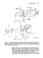
objects produced by the graphical editors. At the second level, the PELLPACK language processor compiles this high
level problem and solution specification into a procedural driver program. In the third level, the driver program
invokes various library modules to realize the user’s solution process. These three programming levels are illustrated
in Figure 11.
FIGURE 11. Three level programming view of PELLPACK
TABLE 2. PELLPACK Subsystems
3.2 THE SUBSYSTEM VIEW
The functionality of PELLPACK is organized into four subsystems. These subsystems represent the solution process
that application users follow. The PDE Problem Specification Subsystem, PDE Solution Specification Subsystem and
Post-processing Environment Subsystem provide users with graphical editors, “foreign” system templates, the PELL-
PACK language and a facility for embedding Fortran code. The Execution Environment Subsystem provides a frame-
Subsystems Components
PDE problem specification Editors, foreign templates, PDE language and embedded fortran
PDE solution specification Editors, foreign templates, PDE language and embedded Fortran
Execution environment Language processor:
Solver module database, program templates and preprocessor
PDE libraries:
ELLPACK, PELLPACK, foreign solvers
ExecuteTool:
Target platform properties database, libraries and editor
Post-processing environment Visualization tools, performance analyzers and editor
BLAS
framework
equation
domain
algorithm
mesh/grid
output
decomposition
bc
FORTRAN
PELLPACK Language
Parallel Tools
Visual System
Expert System
Geometry Modeler
MAXIMA
Scientific
//Macros
&
Comm
Machine
Abstractions
Libraries
Knowledge-based Editor
Very High Level
Procedural Programming
PDE Language Layer
program
Module
Language
Processor
Database
Layer
Layer
June 11, 1997 18
work for processing, compiling, and executing PELLPACK programs. It consists of a language processor, PDE
libraries, and the ExecuteTool. The language processor uses the high level PDE language specification produced by
the graphical editors of the problem and solution specification subsystems to generate a driver program. It can also be
used to integrate new PDE solver components to the PELLPACK system.The PDE libraries implement sequential
and parallel solver components that are available to users via the solution specification subsystem. They include the
ELLPACK solver library, the PELLPACK solver library and “foreign” solver libraries such as FIDISOL, VECFEM,
PDECOL and PDEONE. The ExecuteTool helps users compile and execute programs on all the hardware and soft-
ware platforms that PELLPACK supports by managing the complexities associated with sequential and multi-plat-
form parallel execution Table 2 summarizes the subsystems. This subsystem view of PELLPACK is illustrated by the
vertical layers of Figure 12. Contained in each vertical layer are the PELLPACK programs and libraries that support
the subsystem represented by that layer.
FIGURE 12. The subsystem (vertical) view and the software layered (horizontal) view of PELLPACK
Performance
Analysis Tools
PDE
Specification
Problem
Initial &Boundary
Condition Editors
Algorithm
Editors
Knowledge
Bases
Pellpack Solver
Libraries
Execution
Environment
Visualization
Tools
Post-processing
Environment
PELLPACK
Programming
Environment
PDE
Specification
Solution
PDE Framework
Specification
Data Analysis
Tools
Geometry
PELLPACK
Infrastructure
System
Infrastructure
Execute
Tool
X Toolkit, Motif, Mesa Libraries
Geometry
Editrors
Solution
Specification
Framework
Domain
Libraries
Discretization
Very High Level PDE Language Layer
Procedural Language Layer
Language
Infrastructure
PYTHIA
Geometry
Libraries
Decomposition
Equation
Editor
MAXIMA
“Foreign”
Libraries
System
Modeling
Libraries
Data
Visualization
Libraries
Parallel
Libraries
Communication
Foreign Interface
Libraries
June 11, 1997 19
3.3 THE SOFTWARE LAYERED VIEW
The software is implemented in five layers: the Programming Environment layer, the PELLPACK Very High Level
Language (VHLL) layer, the Procedural Language (Fortran) layer, the PELLPACK Infrastructure layer and the Sys-
tem Infrastructure layer. This view of the PELLPACK architecture and the specific programs and libraries contained
in each layer are illustrated in Figure 12. Notice that the Language Infrastructure layer consists of two software layers
supporting the VHLL layer and the procedural (code generation) language layer. Figure 12 shows the software view
as horizontal layers which span the (vertical) subsystem layers. This figure illustrates how the PELLPACK architec-
ture can be viewed from the standpoint of functionality and from the standpoint of system design.
The implementation language and code size for each software layer are listed in Table 3. Table entries for the System
Infrastructure layer do not include generic system utilities such as X, Motif, etc.
TABLE 3. PELLPACK software layers, implementation languages, and lines of code
The next four subsections discuss the architecture of the top four software layers in more detail.
3.3.1 PROGRAMMING ENVIRONMENT (GRAPHICAL USER INTERFACE)
The GUI of PELLPACK serves two main purposes: PELLPACK program building and solution/performance visual-
ization/analysis. The GUI supports multiple problem sessions within the same process. Each session represents a sin-
gle problem to be solved. The tools that are made available to the user within a session are dependent on the type of
session: 1-D, 2-D, 3-D and finite difference / finite element. Different tools support a different part of the problem
specification or the solution specification. As the problem and solution are being defined, the session editor reflects
the current status by displaying the specification in the PELLPACK language. The user may choose to edit the lan-
guage directly as well, but in order to maintain consistency the user must not be running any of the graphical tools at
the same time. For solution and performance visualization and analysis, the user specifies where to save the appropri-
ate data at problem specification time and the visualization environment loads this data at postprocessing time to visu-
alize the results.
While the graphical tools are active, the current PELLPACK program is internally represented in a set of data struc-
tures in a parsed form. In addition, it is textually represented within the session editor for the user’s benefit and com-
fort. Each tool manipulates one or more pieces of this data structure and is responsible for leaving them in a
consistent state. In some cases, a tool is actually a separate process. Then, the appropriate data structures are commu-
nicated to the other process via inter-process communication and made consistent when the changes are “committed.”
The tools also have a dependency relationship; for example, the mesh tool cannot be invoked until a domain has been
specified. This is supported by having the tools themselves be aware of their position in the chain of operation and
having them do the appropriate tests to ensure that the proper order is maintained.
Layer Implementation language Lines of Code
Programming environment
(Graphical user interface)
C, C++, Tcl/Tk, Perl, lisp, mac, flex,
bison
172,000
Language infrastructure:
Very high level language interface
Fortran, custom parser generator (tp, pg) 80,000
Language infrastructure:
Procedural language (Fortran) interface
PELLPACK infrastructure: PELLPACK
and “foreign” system interface libraries
Fortran, C 175,000
System infrastructure: MAXIMA, “for-
eign” PDE libraries, parallel communica-
tion libraries, visualization libraries/tools.
Fortran, C,C++, lisp, mac 1,500,000
June 11, 1997 20
3.3.2 VERY HIGH LEVEL LANGUAGE INTERFACE
The PELLPACK language interface gives full flexibility to the user to specify their PDE problems and solution
framework using a convenient, high level PDE-specific language. The language uses segments based on the natural
components of the PDE problem and the solution process. The user may write a program in this language directly or
use the graphical user interface to automatically generate the program.
The language processor translates the PELLPACK program into a FORTRAN control program that invokes the
appropriate library components to solve the problem according to the user’s specifications. Each problem component
is transformed into the PELLPACK standard representation for it. Each solution step is converted to the call(s) to the
appropriate solver library using the standard interfaces described earlier. The resulting control program is then linked
with the appropriate libraries to build the program for solving the problem. If the problem is to be solved in parallel,
then there may be more than one control program based on the model of execution selected (see Section 5).
In order for the language processor to be able to generate the control program, information about the top-level calls
for each library module must be given to the system at the time a library is integrated into the system. In addition,
memory requirements of the module must be explicitly stated here so that the control program can allocate memory
before calling the module. This information is kept in a module database and looked up at language translation time.
3.3.3 PROCEDURAL LANGUAGE (FORTRAN) INTERFACE
The Fortran interface of PELLPACK is defined based on a decomposition of the PDE problem and the solution
framework into their constituent parts: domain, interior equation, boundary conditions and initial conditions for the
problem, domain discretization, domain decomposition, operator discretization and algebraic system solution for the
solution framework. Each problem part is represented at run-time using a set of standard data structures and/or func-
tions. Each solution framework part (e.g., an operator discretizer) uses a set of well-defined data structures (inter-
faces) and/or functions for input and output. In addition, each such part may use and/or set certain global conditions
which imply some properties about that part of the problem at hand. For example, if an operator discretizer notices
that the resulting matrix is symmetric, it may set the “matrix is symmetric” flag and then use a more efficient data
structure for storing the matrix. Solvers are expected to first check the symmetricity flag and then select the appropri-
ate data structures. These definitions extend those of the ELLPACK system [40].
3.4 PELLPACK INFRASTRUCTURE
From a run-time view of the architecture the PELLPACK infrastructure, consisting mainly of PDE system libraries, is
below the Fortran interface (Figure 12), but the libraries themselves are integrated to the PELLPACK system based
on their compliance with the component interfaces. The entire PELLPACK collection of solvers is composed in this
manner, i.e., there is no intrinsic or built-in set of libraries. Some libraries (most notably, the ELLPACK libraries of
sequential solvers and the PELLPACK libraries of parallel solvers) natively support the PELLPACK component
interface standards and hence can be “plugged-in” to the system immediately. However, many other libraries (for
example, VECFEM, FIDISOL, PDECOL and MGGHAT) use their own interfaces and representations internally. To
integrate such libraries, one must develop an interface library that transforms the PELLPACK representations pro-
duced by higher levels of the system to the internal representations assumed by the solver library. It is important to
note that due to the structured nature of PDE components and PDE solution frameworks, this is a feasible task; we
have so far not encountered any solver library that could not be integrated in PELLPACK in this manner.
The result of this integrated framework is that components from different libraries can easily be mixed-and-matched
to form interesting and powerful PDE solvers. There is no doubt a performance cost with having a layer of software
that allows this flexibility, but it should be clear that the advantages of having standard interfaces to widely differing
software packages easily outweighs the cost.
June 11, 1997 21
4. THE PELLPACK PROGRAMMING ENVIRONMENT
The implementation of PDE frameworks in PELLPACK provides a three level programming environment depicted in
Figure 11. In this section we give a brief description of PELLPACK programming-in-the-large environment starting
with the PDE language.
4.1 VERY HIGH LEVEL PDE LANGUAGE
In the PELLPACK problem solving environment, a PDE problem is defined in terms of the PDE objects involved:
PDE equations, domain of definition, boundary and initial conditions, solution strategy, output requirements, and
option parameters. The textual representation of the PDE objects and its syntax comprise the PELLPACK language,
which is a significant extension of the ELLPACK language defined in [40]. This language layer is the foundation of
the PELLPACK environment and underlies all levels and components. It defines the intrinsic objects which are
needed to specify a PDE problem and its solution strategy. It is parsed and generated by special editors, and it is
loaded by the execution environment and processed by the language translator into Fortran control program(s) which
are compiled and executed. All PELLPACK system functionality is represented in some way by the PDE language.
In the ELLPACK language, the PDE objects are defined by language segments which either specify the PDE problem
(equation, boundary and associated boundary and initial conditions) or name the module to be used in the solu-
tion process (grid, discretization, indexing, solution, triple
,
output). To support the inser-
tion of arbitrary Fortran code for control and assignment statements, the ELLPACK language uses the
declarations, global, procedure, and Fortran segments. The number and types of segments and
modules which have been added to the original ELLPACK have greatly increased the types of problems that can be
solved and the methods for solving them. The extensions to the ELLPACK language which were defined by PELL-
PACK follow.
PELLPACK introduced a mesh segment to support solution schemes using finite element methods. The integration
of “foreign” solvers required the introduction of tags and specialized identifiers in the option segment for relaying
information about the system solver and its interface requirements to the language processor. The triple segment
is the standard which was adopted to specify the numerical solver associated with a foreign system. The save seg-
ment allows persistent storage of solutions, linear system matrices, and performance data for visualization and/or ani-
mation. Finally, the ELLPACK language and system was extended to support a domain decomposition strategy [21]
to solve PDE problems in parallel on multicomputer platforms. Specifically, the decomposition and paral-
lelsolution segments define the geometry partitioning of the discrete domain and handle the assembly of the
partitioned solutions from the parallel processors. The existence of several parallel execution models necessitates the
use of tags in the option segment (i.e., hostless, Mplus) to identify the parallel model selection.
The language definition of existing segments, modules and module parameters was amplified to contain information
related to the graphical environment. In this way, the language, the graphical interface, and the execution layers work
smoothly together to provide a unified PDE problem solving environment.
4.2 PDE OBJECT BASED GRAPHICAL USER INTERFACE
The process of specifying, solving, and analyzing a PDE problem occurs within a PELLPACK session editor This
editor consists of a text window and an attached toolbox of editors. Figure 13 displays an instance of this editor. The
toolbox editors are used to create or modify the PDE objects which specify the PDE problem and describe how to
solve it. Each toolbox editor is a graphical, interactive tool that generates a textual representation of the object and the
associated PELLPACK language segment in the main session editor window. Editors in the toolbox are able to reload
a PDE object by reading its PELLPACK language representation, and then displaying the object for viewing or mod-
ification. PDE objects are communicated between editors or between an editor and the PELLPACK session editor.
Moreover, these editors may transform objects when needed. For example, domain objects are transported to mesh
editors, where any generator requiring a piecewise-linearization of the boundary will transform the domain object
appropriately. Table 4 lists the editors and their design objective in PELLPACK.
June 11, 1997 22
TABLE 4. The PDE object based editors in PELLPACK
4.2.1 PDE FRAMEWORK SPECIFICATION EDITOR
This editor is used to specify the PDE equations and generate the program framework used for solving the PDE prob-
lem. The format of the framework generated depends upon the PDE-solving system selected by the user. For each of
these systems, certain forms of the equation are valid. For example, PELLPACK solvers allow differential and self-
adjoint forms of the equation; VECFEM allows differential and variational forms. PDE equations are specified via a
graphical interface which has been tailored to the representation of the chosen form of the equation. The editor then
performs the specialized symbolic processing and code generation required for the definition of PDE problems in the
format required by the selected system solver. It generates by default a boundary segment for a rectangular region
with Dirichlet boundary conditions and zero initial condition. Toolbox editors are used to define the actual values of
these PDE objects.
To implement the PELLPACK framework generation, the PDE system is sent in string form to the Maxima computer
algebra system. Depending on the framework, different symbolic transformations are performed. If non-linear equa-
tions are entered for the PELLPACK system solver, these equations are linearized by computing their Frechet deriva-
tives. If FIDISOL or CADSOL is the selected system solver, Jacobians are computed for the specified system of
equations and boundary conditions. A symbolic representation of the PELLPACK template is then developed inside
Maxima. This representation is communicated to the PDE framework specification editor which converts it to a
PELLPACK template using the GENCRAY system [49]. Finally, this template is written in the PELLPACK session
window. All symbolic operations of this editor are provided by Maxima [12].
Editor Design objective
PELLPACK session editable textual representation of the PELLPACK problem and solu-
tion specification
PDE framework specification symbolic PDE operators definition, input functions transformation in
Fortran, linearization, Jacobian, and default framework generation
for each PDE library
Domain and boundary conditions CAD tools for 1-D, 2-D, 3-D domain boundary specification and
auxiliary conditions, or file in some standard format
Mesh generators 2-D, 3-D mesh generators using PELLPACK domain (or other stan-
dard format) as input.
Grid generators 1-D, 2-D, 3-D uniform/non-uniform grid generators
Domain decomposers 2-D, 3-D geometry decomposition using a library of partitioning
heuristics
Discretizers
Linear system solvers
Triples / Foreign system solvers
algorithm specification, where choices for the solution scheme are
controlled by a knowledge base to provide numerical method mod-
ules from the data base (using dimension, domain discretization,
sequential vs. parallel, etc.)
Output specification solution or performance data output format specification
Output visualization visualization and animation of all possible output data produced by
solution (solutions, error analysis, performance data), including nec-
essary data conversion when accessing “integrated” visualizers
June 11, 1997 23
FIGURE 13. An instance of the PELLPACK session editor
In addition to the general PDE frameworks generated by this editor, there are several model specific templates that are
supported. In these cases, users enter the crucial pieces of information that define the problem parameters. These tem-
plates are implemented without support from a computer algebra system. User input is inserted in the appropriate
locations in the template for the selected model, and the result is written in the PELLPACK session window.
4.2.2 DOMAIN AND BOUNDARY CONDITIONS EDITORS
These editors are used to generate the boundary segment and define the PDE domain and boundary conditions. For 1-
D and 2-D domains, PELLPACK provides its own geometry editors. For 3-D cases, PELLPACK supports well estab-
lished geometry interfaces and the XXoX CAD editor [55] for the geometry modeling library XoX Shapes [46].
With the 1-D domain editor, users can define the interval endpoints and assign a boundary condition to each endpoint.
Boundary conditions for 1-D problems which are solved by PDECOL use a foreign system tag to identify the bound-
ary equations in the boundary segment, since the equations are defined in the subprograms segment by Fortran rou-
tines as described in previous sections.
For 2-D domains, PELLPACK provides a 2-D drawing tool where users can draw the boundary piece by piece, and
then assign boundary conditions to each piece. Users may instead define any 2-D boundary parametrically, using the
session editor and following the PELLPACK language syntax. This includes using complicated Fortran functions to
describes boundary pieces, holes and slits. These parameterized functions are then dynamically loaded into the
domain editor so that the domain can be displayed and boundary conditions assigned. Any of these domain defini-
tions can be used as input to the PELLPACK grid and mesh generators. Boundary conditions for foreign systems
either follow the ELLPACK language syntax, or they are tags to foreign system or model-specific identifiers indicat-
ing specialized conditions such as inflow, outflow, wall, etc. All identifiers are handled by the language processor and
the PELLPACK foreign system interface so that the appropriate boundary conditions are applied.
In the 3-D case, box geometries with associated boundary conditions per face can be specified using a 3-D domain
editor. More complicated domains are defined using constructive solid geometry in the XXoX geometry editor.
June 11, 1997 24
XXoX generates surface triangulations which can be used to define the geometry for PELLPACK’s 3-D mesh gener-
ators. Boundary conditions are generally applied discretely on groups of surface nodes (called patches) resulting from
the mesh generating process. PELLPACK provides a 3-D boundary conditions editor which allows users to apply
boundary conditions on surface patches of nodes. Tags or model-specific identifiers may be used to specify the
boundary conditions for foreign system solvers.
For many solvers integrated into PELLPACK, the domain and boundary conditions may be defined outside of PELL-
PACK and saved in files which are then accessed by PELLPACK during the solution process. Packages such as True-
Grid [56] and Patran [2] can be used to define the domain (or subsequent mesh) and boundary conditions.
4.2.3 GRID GENERATION EDITORS
PELLPACK supports both uniform and non-uniform grid generation for 1-D, 2-D, and 3-D domains. For uniform
grids, the number of grid lines in any direction can be specified. Non-uniform grids are specified by point-and-click
(to add, move or delete grid lines) or by listing coordinates. Grids can be uniform in one direction and non-uniform in
another. For collocation methods based on tensor product spline basis functions, the 2-D grid editor and the corre-
sponding overlay grid to a domain can be used to generate and display the collocation meshes and points. In addition,
PELLPACK supports a body-oriented grid generator. It allows users to define the mapping of an arbitrary domain to a
four-sided domain, and allows the specification of an arbitrary number of grid lines per piece of the original domain
definition. The body-oriented grid generator supports systems such as CADSOL, which require a body-oriented grid
for the solution method.
4.2.4 MESH GENERATION EDITOR
This editor is the driver and graphical interface to the finite element mesh generators integrated in PELLPACK. The
available mesh generators are listed in Table 5. For 2-D mesh generators, boundary conditions which have been
defined on the original domain boundary pieces are maintained throughout the mesh generation process. Thus, the
element edges on the domain boundary inherit the conditions of the original boundary piece. These meshes can be
graphically modified by moving appropriate nodes. In the 3-D case, boundary conditions defined on the surface trian-
gulations are maintained throughout the mesh generation process, so that additional faces on the surface inherit the
appropriate boundary condition. A 3-D mesh editor is also available to display or modify 3-D meshes and boundary
condition assignments.
TABLE 5. PELLPACK supported mesh generators and their applicability
Mesh generator Domain definition Description
2-D triangular PELLPACK domain editor
for given edge length, generates a uniform,
triangular mesh and outputs a PELLPACK
mesh format file
2-D adaptive
piece-wise linear approximation
of domain from PELLPACK
domain editor
uses quadtree method to generate a first-cut
mesh which users refine by point-and-click,
outputs a PELLPACK mesh format file
2-D structured
arbitrary domain from
PELLPACK domain editor is
mapped to 4-sided figure
user specifies any number of “points” per side
on original domain then structured mesh is
generated, outputs a PELLPACK mesh format
file
2-D QMG [37]
piece-wise linear approximation
of domain from PELLPACK
domain editor
user specifies maximum edge length which is
used to generate a mesh using the quadtree
algorithm and the mesh is refined by
subsequent applications of algorithm, outputs a
neutral [2] format file.
June 11, 1997 25
4.2.5 DOMAIN DECOMPOSITION EDITOR
The decomposition editor supports the decomposition of meshes/grids into “balanced” subdomains. These data are
used to parallelize the underlying PDE computations. A library of partitioning algorithms is provided to automati-
cally generate the decomposition. These algorithms produce decompositions that balance the load among processors
and minimize communication between processors. Users may choose from many automatic partioning heuristics,
such as Inertia Axis, Neighborhood Search, Recursive Spectral Bisection, and others. These algorithms allow users to
specify numerous input parameters which control the partitioning process. In addition, decompositions can be modi-
fied manually. The decomposition data is written to file(s) used uniformly across all supported target parallel plat-
forms, communication libraries, and execution models (hosted, hostless, Mplus, Dplus). Extensive parallel processing
performance data has been collected using the PELLPACK environment, comparing and analyzing algorithms, plat-
forms, communication libraries, and execution models [29],[32],[33].
4.2.6 ALGORITHM AND OUTPUT SPECIFICATION EDITORS
These editors help the user to specify the solution and output segments by visualizing in a menu form the options that
currently exist in various PDE libraries. The ELLPACK and PELLPACK modules which are available for the solution
process depend on the problem description in the session. The problem dimension and selected method (finite differ-
ence or finite element) are used by internal filters to identify the applicable modules displayed in the discretization
and triple menus of the algorithm editor. If the problem language specification has parallel information, only the par-
allel modules are listed in the menus. Any controlling parameters are accessible through the algorithm editor, where
they can be viewed, modified and saved.
For a solution process which uses foreign system solvers, users must specify the appropriate triple module identified
by the framework they selected when defining the problem (e.g., VECFEM, NSC2KE). As in the case of a PELL-
PACK triple, the foreign system triple module represents the entire numerical solution process. Selecting the triple
module and specifying the values of the required parameters is done within the algorithm editor.
To specify output requirements, the output editor may be used for any ELLPACK or PELLPACK solution process.
Foreign system output requirements are identified directly in the triple module as one of the parameters.
4.3 POST-PROCESSING TOOLS
This software layer includes the output tool which is an interactive environment used to analyze and visualize scien-
tific data generated by PELLPACK solvers. It consists of customized and public domain visualization tools used to
visualize and/or animate 1-D, 2-D, and 3-D PDE solution data. Every solver available in PELLPACK including the
integrated foreign systems supports the PELLPACK output file format. In addition, some solvers generate “solution
component” data files, which together with a mesh file describe the problem solution. Any of these file formats can be
loaded into the output tool. Once the data is loaded, all tools that can load the data (or a transformation thereof) are
made available for selection. Tool applicability is based on problem dimension, domain discretization type (grid vs.
mesh), and the possibility for animation (time-dependent solution). When a visualization tool is selected, the output
tool handles all conversions and data transformation required by the visualization tool.
In addition, it contains performance tools that use timing and trace files generated by sequential or parallel PELL-
PACK programs to evaluate the performance of pre-processing and solution modules (the algorithms) and the perfor-
mance of execution models.
3-D Geompack [27]
surface triangulation from 3-D
domain editor (e.g. XXoX)
users specify a set of parameters controlling
edges, angles, etc., and a tetrahedral mesh is
generated, outputs a neutral format file.
3-D QMG [36]
surface triangulation from 3-D
domain editor (e.g. XXoX)
generates a tetrahedral mesh and outputs a
neutral format file