Đo nhiệt độ P9 pps
Bạn đang xem bản rút gọn của tài liệu. Xem và tải ngay bản đầy đủ của tài liệu tại đây (1.84 MB, 32 trang )
10
Automatic
Pyrometers
10
.1
Optical
Systems
All
of
the
types
of
automatic
pyrometers,
listed in
Section
8
.1
and
shown
in
Figure
8 .2
are
considered
in this
chapter
.
To
reach
a
sufficiently
high
measurement
precision,
the
radiation
emitted
by
the
body
under
measurement
is
concentrated
on
the
radiation
detector
by
lenses,
light-guides
or
mirrors
.
Thus,
they
also
reduce
the
pyrometer
viewing
angle
and
consequently
the
necessary
object
diameter
.
It
its
also
essential that
the
pyrometer
optical
system
should
be
able to
aim
properly
at
the
target
.
10
.1 .1
Lenses
Lenses
should
be
made
of
materials characterised
by
:
"
high
transmission
factor
over
a
wide
wavelength
range,
"
high mechanical
strength,
"
possibly
high
working
temperature,
"
good
resistance
to
atmospheric
and
chemical
influences,
"
good
resistance
to
abrasion,
"
good
resistance
to
rapid
temperature
variations
.
As
it
passes
through
the
lens,
as
illustrated
in
Figure
8
.2,
incident
thermal
radiation
is
attenuated
by
absorption
and
reflection
at
both
lens surfaces
.
The same
effects
occur
at
the
sighting
window
.
It
is
normally
enough
to
take
only
one
internal
reflection
into
account
.
Hackforth
(1960)
points
out
that
coated
lenses
are
used
to
reduce
the surface
reflection
factor
.
He
also
notes
that
the
overall
lens
transmission
may
be even
doubled
by
correctly
choosing
the lens
coating
and
its
thickness
.
Materials
such
as
SiO,
ZnS,
Ce0
2
,
MgF
2
and
so
on,
each with
a thickness
equal
to
one
quarter
of
the
wavelength of
the incident
radiation,
are
suitable
.
The
application
range
of
different
optical
materials
depends
upon
their
transmission
factors
as a function
of
the
wavelength
and
on
the
thickness
of
the
lens
or
window
.
In
pyrometry,
the
upper
cut-off
wavelength of
incident infrared
radiation,
caused
by
the lens
material,
is
extremely
important
.
Following
Wien's
displacement
law,
given
in
equation
(8
.11),
this
long wavelength
transmission
limit
determines
the
lowest
temperature
which
the
pyrometer
can
measure
.
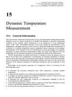
Figure
10
.1
gives
some
of
the
transmission
limits
of
the
more
popular
materials
used
for lenses
and
sighting
windows
of
radiation
pyrometers
.
Temperature Measurement Second Edition
L. Michalski, K. Eckersdorf, J. Kucharski, J. McGhee
Copyright © 2001 John Wiley & Sons Ltd
ISBNs: 0-471-86779-9 (Hardback); 0-470-84613-5 (Electronic)
178
AUTOMATIC
PYROMETERS
KRS
S
(42%Ti8r,
58%
Tl
I)
Go
Asz
S3
FLUORITE
ICaF
)
Li
F
IRTRAN
(M9F
Z
)
SYNTHETIC
SAPPHIRE
(A1
2
O
3
)
QUARTZ
PYREX
GLASS
1
2
3
4
5 6
8
10
20 30 40
WAVELENGTH
X
jim
Figure
10
.1
Transmission
limits
of
some
materials
used
for
pyrometer
lenses
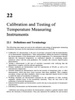
Different
plates
of
known
thickness,
made
of
materials
used
for
pyrometer
lenses,
have
their
relative
spectral
transmission,
zA
,
displayed
as a function
of
the
wavelength
in
Figure
10
.2
(Warnke,
1972,
Baker
et
al
.
1953,
Hackforth, 1960,
Harrison
1960)
.
Commonly
used
lens
materials
are
now
described
.
Pyrex
glass,
transparent
from
0
.3
to
3
pm,
is
used
when
high
mechanical
and
chemical
resistance
is
necessary
.
Quartz
(Si02),
transparent
from
0
.2
to
4
pm,
can
withstand
temperatures
higher
than
those
of
glass,
has
high
mechanical
and
chemical
resistance
and
may
also
withstand
rapid
temperature
variations
.
Synthetic
sapphire
(A1
2
0
3
),
transparent
from
0
.3
to
5
pm,
is
hard
and
abrasion
resistant
.
As
it
can
be
applied
up
to
about
1000
°C
it
is
also
used
for
light
guides
.
Unfortunately
it is
easily
broken
and
cannot
stand
rapid
temperature
variations
.
Fluorite
(calcium
fluoride,
CaF
2
),
transparent
from
0
.1
to
9
.5
[um,
can
be used
for
measuring
temperatures
as
low
as
+50
°C
.
Its
applications
are
limited
by
low
mechanical
strength,
100
v
Asp
5
3
aR
80
E
1
1
i
\
z
60
+
r
o
`^
SC
1
z
t
<c
30
KBr
Si
Go!
OjARTZ
`A
.3
n
.
20
4mm
1mm
1mm
;S10,)
i
5mm
w
20
mro
s
jG
:F,
KR5S
+
IRTRAN
AS
.
'a
1mm
'ntn
1,7smm
1
\
t
0,1
0,2
0
.3
0,5
0,7
1
2 3 5
7
10
20
40
WAVELENGTH
"k
,
PM
Figure
10
.2
Spectral transmission,
ra,
of
plates
of
given
thickness
used
for
pyrometer
lenses
OPTICAL
SYSTEMS
179
softness
and
poor
workability
.
KRS-5
(42
%
TlBr,
58
%
T1I), transparent
from
0
.5
to
36
Nrrt
is
now
the
most
commonly
used
material
for
the
lenses
of
low
temperature
pyrometers,
starting
from
-50
°C,
where
its
mechanical
strength
is
adequate
.
Silicon,
transparent
from
8
to
14
pm,
sometimes
replaces
KRS-5,
for
low
temperature
pyrometers
.
The
Ardometer
pyrometer
from
Siemens
AG
(Germany)
uses
this
material
.
Hackforth
(1960)
gives
more
detailed
information
on
lens
and
window
materials
.
Although
most
automatic
pyrometers
are
equipped
with
a
constant
focus
lens,
focusable
optical
systems
are
more
rarely
used
.
Some
pyrometers,
such
as
Cyclops
300
AF, by
Land
Infrared
Ltd, are also
equipped
with
autofocus
systems
.
With
each
pyrometer, producers supply
a
diagram
of
target
diameter,
d,
versus
target
distance,
l,
similar
to
that
shown
in
Figure
10
.3
for a
MiniView
pyrometer
of
the
Cyclops
Series
by
Land
Infrared
Ltd
UK
.
An
approximate
distance
ratio,
l/d,
which
is
sometimes
given,
is
very
useful
in
the
comparison
of
different
pyrometers
.
The
value
of
the distance
ratio
also
enables
a rapid
estimation
of
maximum
necessary
target
diameter,
d,
for a
given
target
distance,
l
.
In
modern
pyrometers
the
optical
system
is
often
equipped
with
a
laser
aiming
device
.
This
permits
that
part
of
the
target,
whose
temperature
is
to
be
measured,
to
be
determined
correctly
.
It
may
be
either
a point
at
the centre
of
the
target
area or a
circular
light
with
a centre
spot
.
10
.1 .2
Light
guides
When
the
objects,
whose
temperature
is
to
be
measured,
are
too
small
or not
easily
accessible,
as
well
as
in
those cases
when
the
pyrometer
would
be
endangered
by
excessive
temperatures,
light
guides
(optical
fibres)
may
successfully
replace
lenses
.
The
operating
principle
of
optical
fibres
is
given
in
Section
6
.1
.
Figure
10
.4
illustrates
the
working
principle
of
a
fibreoptic
pyrometer
.
The
end
of
the
light
guide
is
placed
near
the
object
which
emits
thermal
radiation
.
This
radiation arrives
at
the radiation detector
after
multiple
internal
reflections
from
the
inner
polished
rod
surface
.
Owing
to
absorption
along
the
rod,
imperfect
reflection
from
the
rod
walls
and
reflection
losses
at
the
entrance
and
exit
ends
of
the
rod,
some
of
the
transmitted
energy
is
lost
.
The
efficiency
of
the
energy
transmission
depends
on
the
radiation
entrance
angle,
and
so,
on
the
distances
between
the
object
and
rod
as
well
as
between
the
rod
and
the detector
.
It
is
also
affected
by
the length
and
design
of
the
light
guide
.
Light
guides
are
made
of
artificial
sapphire
(A
1
203)
or
quartz
(Si0
2
)
as a
solid
rod
.
or as a
flexible
stranded
ftbreoptic
cable
of
thin
fibres,
up
to
2
m
long
.
As
described
in
Section
6
.1,
light
guides
can
be
bent,
provided
m
1
3
2,5
2,1
2
1,5
12111
0
0
45
30
30
30
74 70
,
95
6V"
120
Figure
10
.3
Example
of
target
diameter,
d,
versus
target
distance,
l,
for the
optical
system of a
pyrometer
180
AUTOMATICPYROMETERS
FURNACE
OBJECT
~
DETECTOR
LIGHT GUIDE
p
a
PYROMETER
Figure
10
.4
Working
principle
of
fibreoptic
pyrometer
that
the
angle
of
incidence
at
the side
wall
is
always
greater
than
the
critical
angle
.
The
end
of
a
light
guide
facing the
body
under
measurement
is
usually
equipped
with
an
optical
head
having
a
small
diameter,
concentrating
lens
.
10
.1
.3
Mirrors
At
the
lowest
measured
temperatures,
where
no
lenses
may
be
applied,
mirrors
can
be
used
.
As
described
in
Section
8
.2,
they
are
made
of
metals
with
good
electrical
conductivity,
which
are
characterised
by
a
high
reflection factor
at
low
temperatures
and
long
wavelengths
.
Although
mirrors
absorb
less
infrared
radiation
than
lenses,
this
advantage
is
partially
cancelled
by
the
need
to
use
a
protecting
window
.
They
are
made
mainly of
polished
gold,
silver
or
aluminium
of high
reflectivity
.
Gold
has
good
resistance
to
atmospheric
and
chemical
influences,
while
the
other
metals
have
to
be
covered
by
a
protective
coating,
which
is
transparent
to
infrared
.
This
coating
cannot
be
too
thin,
otherwise
it
will
not
act
as a
reflection
reducing
layer
.
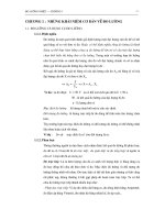
Figure
10
.5
gives
the
specific spectral
reflectivities,
pa,
of
different
metals
as
a function
of
radiation
wavelengths
as
reported
by
Harrison
(1960)
.
Mirror
type pyrometers,
which
are
no
longer
popular, are
only
used
in
some
exceptional
cases
.
1,0
I
.
W
0,6
I .
ALUMINIUM
0,4
SILVER
,4
I
.
-
._
GOLD
COPPER
a
I
I
-
STEEL
0
.2
I
0
0
1
2
3
4
5
WAVELENGTH
R
,
pm
Figure
10
.5
Specific spectral
reflectivities,
pa,
of
metals
for
pyrometer
mirrors
RADIATION
DETECTORS
181
10
.2
Radiation
Detectors
Thermal
radiation
detectors
are
used
in
automatic
total
radiation
pyrometers
.
Photoelectric
detectors
are
used
in
automatic
photoelectric,
two-wavelength
and
multi-wavelength
pyrometers
.
10
.2
.1
Thermal
detectors
Total
radiation
pyrometers
use
thermal
radiation
detectors,
which
are
heated
by
incident
radiation
.
These
detectors
should
have
the
following
properties
:
"
high
sensitivity,
defined
as the
ratio
of
output
signal
to
the incident radiation
power,
"
time
stable properties,
"
high
resistance
to
shocks
and
vibrations,
"
low
thermal
inertia,
"
output
signal
independent
of
the
pyrometer
position,
"
high
output
signal-to-noise
ratio,
"
high
emissivity,
"
sensitivity
independent
of
wavelength
.
Thermopiles,
which
are
the
most
commonly
used
thermoelectric
detectors,
possess
all
these
properties,
together
with
an
easily
measurableor
transformable
output
signal
.
These
detectors are
miniaturised
elements
in
which
the
measuring
junctions
of
a
number
of
series
connected
thermocouples
are
exposed
to
the
incident
radiation
from
the
object,
whose
temperature
is
to
be
measured
.
The
reference junctions
of
the detector are
kept
at
the
pyrometer
housing
temperature
.
Lieneweg
(1975)
asserts
that
a
good
solution
to
the
problem
is
the
enclosure
of
the
thermopile
in
an
air
evacuated
glass
bulb
.
As
well
as
increasing
the
detector
sensitivity
this
eliminates
convective
heat
exchange,
making
the
pyrometer
output
signal
totally
independent
of
the
pyrometer
position
.
Thermopile
types
are
now
described
.
Wire
thermopiles
made
of
thin
thermocouple
wires
of
diameter
0
.1
to 0
.15
mm
with
thin
blackened
plates,
are
used
as
radiation receivers
.
Ribbon
thermopiles
consist
of
thin
thermocouple
ribbons
which
are
0.025
mm
thick
and
0
.5
mm
wide
.
They
are
soldered
or
welded
together
with
one
surface
blackened
to
form
the
radiation
receiver
.
Thin film
thermopiles
are
deposited
on
a
non-metallic
plate,
which
is
the
radiation
receiver
.
These
types
of
thermopile
have
extremely
low
thermal
inertia,
having
a
time
constant
even
as
low
as 15
ms
.
Hair
pin
thermopiles
are
similar
to
wire
thermopiles
but
have
much
larger cross-sections,
thus
preventing
brittle
effect
breakage
.
They
are
made
of
R-tellur-bismuth
with
a
really
high
sensitivity
,
of
600
pV/K
.
The
larger
cross-sections
are
possible
due
to
the
low
thermal
conductivity
of
both
metals
.
Thermistor
and
metal
bolometerN
which
are
also used, are
constructed
in
thin film
technology,
with
a
resistance
of
1
to
5
MO
.
In
most
cases
they
are
used
in ac
bridge
circuits
to
allow
easy
amplification
of
the
output
signals
.
Sometimes
a
do
bridge
circuit,
with
modulationof
incident
radiation,
is
used
.
Baker
et
al
.
(1953)
report
that
the
time
constants
of
bolometers
are
from
1
to 16
ms
.
182
AUTOMATIC
PYROMETERS
Pyroelectric
detectors
are
also
used
in
low
temperature
radiation
pyrometers
(Lang,
1972)
.
They
are
based
on
the
phenomenon
that
the
dipole
moments
of
the
charges
in
pyroelectric
crystals,
such
as triglicine
sulphate
(TGS)
change
their
orientation
as
a
function
of
temperature
.
As
the
temperature
varies,
a
temporary
imbalance
of
charges appears
so
that
an
easily
amplified
alternating
voltage
which
is
modulated
by
the
incident
radiation
flux,
is
generated
.
Despite
their
very high
sensitivity,
pyroelectric detectors are
rarely
used,
because
of
the
complicated
construction
ofpyrometers
with
modulationof
incident
radiation
.
10
.2 .2
Photoelectric
detectors
Photoconductors,
photodiodes,
photovoltaic
cells
and
vacuum
photocells
all
belong
to
this
group
of
detectors
.
Photoconductors
(also
called photoresistors) are
built
from
glass plates
with
thin
film
coatings
of
thickness
1
pm,
from
the materials
PbS,
CdS,
PbSe
or
PbTe
.
When
the incident
radiation
has
the
same
wavelength
as
the
materials
are able
to
absorb,
the
captured
incident
photons
free
photoelectrons,
which
are then able
to
form
a
conducting
electric
current
.
As
the
resistance
of
a
photoconductor,
which
decreases
with
increasing
radiation
intensity,
also
depends
on
its
temperature,
this
phenomenon
has
to
be
considered
in
the construction
of
a
pyrometer
.
If not
irradiated
the
`dark'
resistance
of
a
photoconductor
is
from
10
¢
to 10
,
S2
.
Considering
that
the
photoconductor
sensitivity
depends
on
the
radiation
wavelength,
the
concept
of
the
operating
wavelength
band,
can
be
introduced
.
Since
the
sensitivity
and
spectral
response
of
photoconductors
undergo
some
changes
with
ambient
temperature
and
time,
they
are
applied
in
most
cases
as
a
null
detector
.
This
may
be
achieved
by
comparing,
for
instance,
two
radiation
intensities,
falling
alternatively
upon
its
surface
.
In
most
cases
the surface
of
a
photoconductor
has
to
be
protected
against
atmospheric
influences
by
covering
it
with
a protective
varnish
layer
of
materials
like
polystyrene
.
Photodiodes,
in
germanium
or
silicon,
are
operated
under
a reverse
bias
voltage
.
Their
conductivity
as
well
as
their
reverse
saturation
current,
under
the influence
of
incident
radiation,
is
proportional
to
the
intensity
of
the
radiation
within
the
spectral
response
band
from
0
.4 to
1
.7
hum
for
Ge
and
0
.6
to
1
.1
pm
for
Si
.
The
high
sensitivity
of
photodiodes
permits
the
construction
of pyrometerswith
high
distance
ratios
.
To
compensate
for the
dark
current,
which
occurs
in
the
non-irradiated
state,
a
second
identical
diode, protected
from
radiation,
is
used
.
Photovoltaic
cells,
which
generate
a
voltage
depending
upon
incident
radiation,
are
constructed
with
a
thin
semiconductor
film
deposited
on
a
metal
plate
.
Under
no-load
conditions,
this
generated
voltage
is
a
logarithmic
function
of
the
incident
radiation
intensity
.
They
are
simple
and
robust
in
construction
.
As
photovoltaic
cells
generate
strong
output
signals
that
can
be
utilised
without
any
further
amplification,
there
is
no need
to
apply
any
external
voltage
.
However,
because
their sensitivity
is
low
in
the
infrared
range,
they
can
only
be
used
for
higher
temperatures
.
Materials
used
for
photovoltaic
detectors
are
selenium,
silicon,
indium
antimonide
(InSb)
andindium
arsenide
(InAs)
.
Vacuum
photocells
operate
on
the
principle
that
the
incident infrared
radiation
causes
the
emission
of
electrons
from
a
metallic
photocathode,
which
is
placed
in
a
vacuum
glass
bulb
with
an
anode
.
Ata
given
do
voltage
between
cathode
and
anode,
the
electric
current
is
a
I
~
1
.
"
.
MEN
m
III
I
184
AUTOMATIC
PYROMETERS
Table
10
.1
Commonly
used
photoelectric
radiation
detectors
(Wamke,
1972)
.
Wavelength,
A
Corresponding
to
Maximum
maximum
detector
operating
value,
sensitivity
ANBX
(Pm)
Resistance
Time
constant,
Detector
(pm)
(S2)
(lIs)
Ge
1 .2
1 .8
1
Si
0
.9
1
.2
10
7
=1
PbS
2-2
.4
2
.3-3
.1
10
6
-10
7
150-500
InAs
3
.4
3
.7
20
2
InSb
6
.0
7
.0
4
.5-9
<1
the
monochromatic
radiation
wavelength
and
at
the
applied
frequency,
f
o
,
of
the
optical
modulation
up
to
about
1
kHz
.
10
.3
Total
Radiation
Pyrometers
10
.3 .1
General
information
In
total
radiation
pyrometers
the
temperature
of
a
body
is
determined
by
the
thermal
radiation,
which
it
emits
over
a
large
range
of
wavelengths
.
This
radiation
is
concentrated
onto
a
thermal
radiation detector
by
a
lightguide
as
shown
previously
in
Figure
10
.4
or
by
a
lens
or
mirror
system
as
shown
in
Figure
10
.7
.
Heating
of
the
thermal
detector
by
the
concentrated
incident
thermal
radiation
gives
a detector
output
signal,
which
is
proportional
to
its
temperature
and
thus
at
the
same
time
to
the
value
of
the
measured
temperature
.
A
total
radiation
pyrometer
using
a
lens,
was
first
constructed
by
Fery
(1902)
who
later
(Fery,
1908)
also
used
a
concave
mirror
in
1904
.
Pyrometers
may
have
an
optical
system
with
fixed or adjustable
focal
length
.
The
former
type
is
now
more
popular
.
TARGET
LENS
THERMAL
DETECTOR
OBSERVER
/EYE
I
I
I
______
-
_ J
MEASURING
OKULAR
INSTRUMENT
LENS
SYSTEM
°C
M
Im
PROTECTING
WINDOW
MIRROR
I
I
r
I
MIRRORSYSTEM
M
Figure
10
.7
Basic diagrams of
total
radiation
pyrometers
TOTAL
RADIATION
PYROMETERS
185
10
.3 .2
Scale
defining
equation
for
black
bodies
Consider
a
pyrometer
shown
in
a simplified
way
in
Figure
10
.8
.
The
thermal
radiation,
emitted
by
a
black
body,
1,
whose
temperature,
T
t
,
is
to
be
measured,
passes
through
a
window
before
falling
onto
a
thermal
detector
plate,
2
.
The
window
side
of
this
plate
is
blackened
to
give as
highan
emissivity
as
possible
while
its
other
side
should
have
as
low
an
emissivity
as
possible
.
The
incident
thermal
radiation heats
the
plate
up
to a
certain
temperature,
Tp,
which
is
measured
by
a
thermocouple
or a
thermopile
.
A
reference
junction
temperature
for
this
thermopile
is
provided
by
the
temperature,
T
H
,
of
the
pyrometer
housing
.
Although
there
is
no
concentrating
optical
system
in
the
form
of
a
lens
or
mirror
in
the
vastly simplified
Figure
10
.8,
neither
the
working
principle
nor
the
sensitivity
of
the
pyrometer
are
altered
.
This
is
apparent
as the existence
of
a
concentrating
optical
system
only
reduces
the
necessary
area
of
the
radiating
body
.
On
the surface
of
the
detector
plate,
the
heat
flux
density
of
the
flux,
emitted
by
the
body
and
absorbed
by
the
plate,
is
given
by
:
Rl
)
2
-_
6,E2
K
t
sin
g
tp(T
t
4
-
T
p
)
(10
.2)
where
6
o
is
the
radiation
constant
from
equation
(8
.16),
E2
is
the
total
emissivity
of
the
blackened
side
of
the detector
plate,
K
i
is
a
coefficient
depending
on
the
construction
of
the
pyrometer
and
the
absorption
of
the
optical
system,
T
t
is
the
true,
measured
temperature
of
the
blackbody,
T
p
is
the
plate
temperature
and
(p is
the
viewing
angle
given
in
Figure
10
.8
.
Instead
of
the
viewing
angle
some
producers
give the
ratio
of
working
distance,
l,
to
the
minimum
target
diameter,
d,
(Figure
10
.8)
or
simply the
distance
ratio
.
An
increasing
number
of
producers
now
supply
more
precise
and
more
convenient
diagramsof
the
target
diameter
versus
working
distance
.
Figure
10
.3 is
a
typical
example
of
such
diagrams
.
In
practice,
when
the detector
plate
has
very
,
small
dimensions,
its
viewing
angle,
(fi ,
is
the
same
all
over
its
surface
.
Thus
the
thermal
flux,
or
heating
power
absorbed
by
the
plate
is
given
by
:
(D1
-)
2
°
CV
2K,
A
p
sin
e
!p(T
4
-
TP)
(10
.3)
where
A
p
is
the
one
side plate area
and
the
other
symbols
are as
in
equation
(10
.2)
.
THERMAL
DETECTOR
PLATE
HOUSING
WINDOW
T
2
T
H
T
P
BLACK
BODY
THERMOPILE
I
Figure
10
.8
Total
radiation
pyrometer
-
simplified
design
186
AUTOMATIC
PYROMETERS
As
the
area
of
the
plate,
A
P
,
is
much
smaller
than
the
inner area
of
the
pyrometer
housing,
and
neglecting
the radiant
heat
exchange
at
the
unblackened
back
side
of the
plate,
the
total
heat
flux
transmitted
from
the
plate
to
the
pyrometer
housing
is
expressed
as
:
'D2
I
x
=6oE2KtAP(Tp-TH)+K2(Tp-TH)
(10
.4)
where
K
2
is
the
heat
transfer
coefficient
by
convection
and
conduction
from
the
plate
to
the
housing
and
the
other
symbols
are
as in
equation
(10
.3)
.
When
the
plate
is
in
the
thermal
steady-state,
the
received
radiant
heat
flux
(D
I
,
2
equals
the heat flux
(D2
,
H
transferred
to
the
pyrometer
housing
so
that
:
4
4
6o
E2
K,Apsin2cp(Tt4-Tp
)
=6
.E2KIAp(Tp
-TH)+K2(Tp-TH)
(10
.5)
The
output
signal
of
the
pyrometer,
which
is
the
thermal emf,
E,
of
the
thermocouple or
thermopile
of
Figure
10
.8 is
a nearly
linear
function
of
the
temperature
difference
between
the
plate
temperature,
T
p
,
and
that
of
the
housing,
T
H
,
is
thus
given
by
:
E=
Ke(TP-TH)
(10
.6)
where
K
e
is
the
thermocouple
gain,
mV/K
.
The
gain
of
a
thermopile,
composed
of
n
thermocouples
is,
nK
e
.
Calculation
of
the
characteristic
T
p
-
TH
=
f(Tt)
(10
.7)
of
a
pyrometer
is
based
on
the solution
of
equation
(10
.5),
whose
complicated
form
as
well
as
the
temperature
dependence
of E
2
,
K
t
and
K
2
,
excludes
the
possibility
for
a
practical
analytical
solution
.
In
practice,
the
pyrometer
characteristic,
which
is
always
determined
experimentally,
has
the
approximate
form
(Ribaud
et
al
.
1959)
:
E
=
K(T
b
- Tp)
(10
.8)
in
which
the
exponent,
b,
with
a
value
between
3 .5
and
4
.5,
and
the
constant,
K,
depend
on
the
construction
of
the
pyrometer
.
Equation
(10
.8)
concerns
thermocouple
and
thermopile
detectors
.
For
resistance
and
semiconductor
bolometers
other
formulae
are
used
.
10
.3 .3
Temperature
measurement
of
non-black
bodies
Total
radiation
pyrometers
are
calibrated
under
the
assumption
that
the
measuring
target
is
a
black
body
.
From
equation
(10
.3),
the
radiant heat
flux
emitted
by
the
target
at
the
temperature
T
t
and
absorbed
by
the detector
plate
is
given
by
:
TOTAL
RADIATION
PYROMETERS
187
'D1
1
2
=
6
.E2
K
1
A
p
sin
2
(P(Tt4
-
Tp
)
or
introducing
the
coefficient,
K',
it
will
be
:
(
D1,
2
=
Kl
(Lrt4
-
T
p )
(10
.9)
In
practice,
as
usually
T
t
>>
T
p
,
equation
(10
.9)
becomes
:
('112
=
KiTt4
(10
.10)
where
K'
is
a
constructional
constant
.
For
example,
for
T
t
=
2000
K
and
T
p
=
400
K,
Tp = 0
.0016T
4
.
For
non-black
bodies,
having
emissivity
s,
the
radiant
flux
absorbed
by
the detector
plate
will
be
:
(D1/
-,2
=
A
.I'ET
a
(10
.11)
As
a
total
radiation
pyrometer
is
calibrated
for
black
bodies, for
use
in
measuring
the
temperature
of
non-black
bodies, the
indicated
temperature
value,
T
;
,
called
the
black
temperature
is
lower
then
T
t
.
Since
T
;
is
the
temperature,
at
which
the
detector
would
get
the
same
radiant
flux
from
a
blackbody,
then
:
V
1
,
2
=
KiT4
(10
.12)
Equating
(10
.11)
to
(10
.
12),
shows
that
:
T
t
=T°
.
(10
.13)
E
Numericalexample
When
the
temperature
ofa
body
of
E
=
0
.6
was
measured
by
a
total
radiation
pyrometer,
the
indicated
temperature
was
T
t
=
1200
K
.
Calculate the
true
temperature
of
the
body
.
Solution
:
From
equation
(10
.
13)
.
T
t
=1200
4'
-
1
=1370K
V
0
.6
i
1
"
m-
.wo
w
1
m
o
"""""""
~E
""""""
""""""
.
"""""""
_i%
""""
i
"""
""""
PM
"""""
PIrd/
""""
i
oil
off
- .
'
TOTAL
RADIATION
PYROMETERS
189
10
.3 .4
Influence
of
housing
temperature
The
readings
of
a
total
radiation
pyrometer
with
thermocouple
or
thermopile
detectors
depend
on
the
difference
between
the
measuring
junction
or
plate
temperature,
T
p
,
and
the
reference
junction
temperature,
which
equals
the
pyrometer
housing
temperature,
TH
.
To
make
the
readings
independent
of
the
housing
;
temperature,
T
H
,
whose
variations
would
affect
the
pyrometer
readings, the
thermoelectric
radiation
detector
should
be
designed
in
such
a
way,
that
its
heat
losses
to
the
housing
are
a
linear
function
of
the
temperature
difference
T
p
-
TH
.
This
can
be
explained
by
considering
what
happens
if
the
housing
temperature
increases
from
T
H
to
TH
.
This
increased
housing
temperature
will
cause
a
decrease
in
the
emf
of
the
detector
owing
to
the
lower
value
of
the
difference,
T
p
-
T
H
.
A
simultaneous
decrease
in
the
heat
loss
of
the detector also
results
from
the
increase
in
housing
temperature,
which
subsequently
gives
rise
to
an
increase
in
T
p
to
Tp
.
Properly
designed
pyrometers
should
meet
the
condition
:
T
p
-
T
H
=
:Tp
-
TH
(10
.15)
So
that
the
pyrometer
readings
are
independent
of
the
housing
temperature
.
The
compensation
method
described,
sometimes
causes
an
increase
of
the
heat
loss
by
the
detector,
which
results
in
a
decrease
of
the detector
sensitivity
.
Effective
pyrometer
design should
be
a
compromise
between
the
ability
to
compensate
and
pyrometer
sensitivity
.
Other
compensation
methods
will
be
discussed
later,
when
the
various
construction
details
of
some
total
radiation
pyrometers
are
described
.
10
.3 .5
Influence
of
target
distance
For
pyrometer
readings
to
be
correct,
the
whole
field
of
view
should
be
filled
by
the target
area,
so
that
the
whole
detector
plate
is
irradiated
by
the
source
radiation
.
This
also
means
that
the
rotational
cone
base
of
Figure
10
.8 is
fully
covered
by
the
measured
target
surface
.
In
this
case,
the
total
radiation
energy
received
by
the
detector
plate
is
the
same
for
any
target
distance
.
No
absorption
of the
radiant
flux
during
its
transit
between
the
target
and
pyrometer
has
been
considered
so
far
.
10
.3
.6
Extension
of
measurement
range
Extension
of
the
measurement
rangetowards
higher
temperatures
is
possible
by
weakening
the
radiant
flux
coming
from
the
object
.
Grey
filters
are
used
for
this
purpose
.
The
radiant
flux
absorbed
by
the
detector
plate
is
given
by
equation
(10
.10)
as
:
4
'DI
-~
2
'"
K1Tt
190
AUTOMATIC
PYROMETERS
Let
the
corresponding
pyrometer
indication,
Ti,
remain
the
same,
while
assuming
that
a
grey
filter
with
the
transmission
factor,
z1,
is
used
.
Of
course
this
is
possible
at
another
higher
object
temperature,
Tt,
at
which
the
radiant
flux
is
:
`f1 >
2
=
Kizl(Tt~
4
(10
.16)
where
zl
is
the
filter
transmission
factor
and
Tt
is
the
new
object
temperature
.
By
equating
equations
(10
.10)
and
(10
.16)
it
is
apparent
that
:
Tt4
=
z1(Tt74
(10
.17)
As
the indicated
and
true
temperature
for
black
bodies
and
for
a
pyrometer
without
filter
are
equal,
it
follows
that
:
T
i
=T
t
(10
.19)
so
that
eventually
:
T
=
Tt4
zl
(10
.19a)
whereT
is
the
reading
of
pyrometer
with
grey
filter
and
Tt
is
the
measured
temperature
.
The
grey
filter,
used
for
extension
of
the
temperature
range,
may
be
pushed
in
and
out
so
that
the
pyrometer
has
two
temperature
scales
.
One
is
the
lower
temperature
range
and
the
other
used
with
a
grey
filter,
is
the
higher
temperature
range
.
In
many
pyrometers,
exchangeable
optics
are also
used
for
changing
the
temperature
range
.
10
.3 .7
Review
of
construction
A
total
radiation
pyrometer
called
an
Ardometer
has
been produced
by
Siemens
AG
(Germany)
since
1920
.
Figure
10.10
shows
a
stationary
ARDOMETER
MPZ
in
its
present
form
and
Figure
10
.11
its
block
diagram
(Siemens
AG,
1998)
.
i
Figure
10
.10
Stationary
total
radiation
pyrometer
ARDOMETER
MPZ
(Courtesy
of
Siemens
AG)
TOTAL
RADIATION
PYROMETERS
191
TARGET
THERMOPILE
E
N
0
0
o=20MA
.
-
D
A
t'
P
A
1
4
20mA
jJ
LENS
HOUSING
TEMPERATURE
SENSOR
RS232
INTERFACE
Figure
10
.11
Simplified
block
diagram
of
ARDOMETER
MPZ
(Courtesy
of
Siemens
AG)
The
lens
concentrates
the incident
radiation
on
a
thin-film
thermopile,
heated
up
to
a
temperature
proportional
to
the
measured
temperature
.
The
thermopile
output
signal
is
also
a
function
of
the
pyrometer
housing
temperature,
being
at
the
same
time
the
thermopile
reference
temperature
.
This
influence
is
compensated
by
a
Ni
resistor
in
the
temperature
range
0
to
60 °C
.
The main
technical
parameters
of
the
pyrometer
are
as
follows
:
"
measuring
range
:
adjustable
from
0
to
1000
°C,
"
spectral
response
:
8 to
14
gym,
"
distance
ratio
:
38
:1,
min
target
distance
:
0
.15
to
0
.3
m,
"
output
signal
:
-
analogue
:
0-20
mA
or 4-20
mA,
-
digital
:
periodical,
RS232,
"
response
time
:
<100
ms
"
linearisation
:
digital
by
microprocessor,
"
accuracy
:
±1
%
of
reading
(min
±2
°C),
"
focusing
:
through
the
lens
with
marked
target
area,
"
measuring
mode
:
normal,
peak
and
valley
picker,
"
emissivity
adjustable
:
0
.100
to
0
.999,
"
weight
:
0
.75
kg,
dimensions
:
d=80,1=220
mm,
"
microprocessor
based
electronics
.
The
pyrometer
also
enables
the
measurement
of
average
value
with
corresponding
time
constant
adjustable
from
0
to
10
s
.
An
example
of
a
portable
total
radiation
pyrometer
is
the Portix
D
pyrometer
made
by
Keller
GmbH,
shown
in
Figure
10
.12
.
This
microprocessor based
pyrometer,
which
has
a
measuring
range
of
0-600
°C,
operates
in
the
wavelength
range
of
8-16
ltm
.
With
a
distance
ratio
of
1/d
;
t
11,
the
pyrometer
can
measure
targets
with
diameters
bigger
than
55
nun
from
a distance
of
about
0
.6
m
using
a
thin-film,
thermopile
detector
.
It is
also
equipped
with
a
microprocessor based
peak
and
valley picker
as well as a
facility
to
store
64
readings,
which
can
be
displayed
on
a
3'/z
digit
LCD
.
The
emissivity
may
be
set
between
0
.2 to
1
.0
in
0
.001
steps
.
As
an
option
a special
Adaptix
C
module
allows connection
to
a
PC
using
an
RS232
interface
.
Keller
GmbH
also
offers
a
whole
family
of
Cellatemp
PS
small
total
radiation
pyrometers,
equipped
with
thin
film
thermopile
detectors
.
The
dimension
of
this
pyrometer
head
is
d = 30
mm,
1=
190
mm
.
The
linear
output
signal
of
this
pyrometer
is
0(4)-20
mA
do
and
the
response
time
is
about
80
ms
to
200
ms
for
different
temperature
192
AUTOMATIC
PYROMETERS
i
Figure
10
.12
Small
portable
radiation
pyrometer
-
Portix
D
(Courtesy
of
Keller
GmbH)
ranges
.
The
pyrometer
heads
are
delivered
with
the
read-out
instrument
recorder
or
controller
.
The
measuring
range
of
these
pyrometers
is
between
-30
°C
and
+2500
°C,
divided
into
seven
sub-ranges
for
different
types
.
It
is,
for
example,
-30
°C
to
+70
°C
for type
PS
12,
0
°C
to
+500
°C
for
type
PS
13
and
up
to
+300
°C
to
2500
°C
for
type
PS4142
.
The
operating
wavelength
is
8
to
14
pm
and
the distance
ratio
is,
1/d
of
10
to
30
.
Air
or
water
cooled
mountings
for
pyrometer
heads
and
lens
protection devices
are
also
available
.
Raytek
Corp
.
produces
miniature
radiation
sensors type
MI
and
ET,
with
thermopile
detectors,
having
a
98
%
response
time
of
300
to
500
ms
(Raytek,
1995,
1996)
.
They
have
the
output
signal
versus
temperature
dependence
conforming
with
that
of
standard
type
J,
K
and
R
thermocouples
or
having
a
4-20
mA
output
.
Being
extremely
small
and
robust
they
are
installed
in
many
industrial
plants for
temperature
measurement,
recording
and
control
.
The
technical
data
of
these
sensors
are
given
in
Table
10
.2
10
.4
Photoelectric
Pyrometers
10
.4 .1
General
information
The
thermal
inertia
of
these
thermal
radiation
detectors
described
in
Section
10
.3
permits
the
measurement
of
rapidly
changing
temperatures
.
For
example,
whereas
the
smallest
time
constant
of
a
thermal
detector
such
as
a
bolometer
is
about
1
ms
or
of
a
thermopile
is
15
ms,
the
smallest
time
constant
of
photoelectric detectors
can
be
about
1
or
2
Ps
.
It
has
been
pointed
out
by
Larsen
and
Shenk
(1941)
that
although
H
.
E
.
Ives
proposed
the
use
of
photoelements
for
temperature
measurement
as
early
as
1923,
the
first
industrial
photoelectric
pyrometers
did
not
appear
on
the
market
until
1932
.
PHOTOELECTRIC
PYROMETERS
193
Table
10
.2
Technical
data
of
miniature
radiation
sensors
types
MI
and
ET
(Raytek
Corp
.
1995,
1996
.)
Technical
Typ
e
parameters
M120 M140
M1100
ET
2
LT*
Temperature
range
(°C)
for
outputs
:
type
J
thermocouple
0-180
0-180
0-180
-18-760
type
K
thermocouple
0-500
0-500
0-500
0-870
0-5
V
0-500
0-500
0-500
-
Wavelength
range
(pm)
7
.6-18
7
.6-18
7
.6-18
8-14
Distance
ratio
2
4
10
33
Dimensions
(mm)
d
=
1
4
;
1= 28
d
=
57
;
1= 180
*
emissivity
adjustable
from
0
.1-1 .0
LENS
°C
M
D
N
TARGET
DETECTOR
INDICATOR
Figure
10
.13
Basic
diagram
of
a
photoelectric
pyrometer
with
direct
radiant
flux
In
pyrometers
with
modulated
radiant
flux
other
less
stable
photoelectric
detectors
such
as a
PbS
photoconductor
or a
InSb
or
InAs
photovoltaic
cell,
can
be used
.
Modulation
of
the
incident radiant
flux,
as
shown
in
Figure
10
.14,
is
obtained
either
by
a
rotating
disk
with
apertures or
by
using
a
vibrating
fork
.
In
order
to
prevent
any
disturbances
which
may
be
synchronous
with
the
mains
frequency
the
modulation
frequency
has
to
be
different
from
the
mains
frequency
or
its
harmonics
.
The
working
wavelength
band
of
a photoelectric
pyrometer
depends
upon
the
spectral
sensitivity
of
the
photoelement
(Figure
10
.6,
Table
10
.1),
upon
the
spectral
transmission
of
the
lens
(Figure
10
.1
and
10
.2)
and
upon
the
filter
used
if
any
.
Pyrometers
with
very narrow
operating
wavelength
band
are
called
monochromatic
pyrometers
and
others are called
band
pyrometers
.
The
correct
choice
of
pyrometer
working
band
enables
its
properties
to
be
adapted
to
different
operating conditions
and
applications
.
This
problem
will
be
discussed
in
Section
10
.4 .3
dealing
with temperature
measurement
of
non-black bodies and
in
TARGET
ROTATING
DISK
LENS
MOTOR
°C
D
-ru-
/
M
'v_
PHOTOCONDUCTOR
INDICATOR
Figure
10
.14
Basic
diagram
of
a
photoelectric
pyrometer
with
modulated
radiant
flux
194
AUTOMATIC
PYROMETERS
Chapter
11
.
The
factor
deciding
on
the
choice
of wavelength
or
the
wavelength
band
in
which
the
photoelectric
pyrometer
has
to
operate
is
the
atmospheric
absorption
.
Figure
10
.15,
which shows
the
spectral
transmission,
z~,,
of
the
atmosphere
and
also the
absorption
free
atmospheric
windows,
is
based
upon
information
presented
in
Lotzer (1976)
and
Warnke
(1972)
.
Many
contemporary
pyrometers
operate
in these
wavelength
ranges
.
The
disturbing influences
of
sunlight
can
be
avoided
by
choosing
the 8
to
141tm
wavelength
range
.
A
photoelectric
pyrometer
is
characterised
by
a
feature
called
its
reference
wavelength,
at
which
the
temperature
is
being
measured
.
When
the
response
band
is
not
too
wide,
its
weighted
mean
value
or
effective
wavelength,
~,,
can
be used
.
This
wavelength
is
such
that
the
calibration
of
the
pyrometer
over
a
certain
range
of
temperatures
is
the
same
as
that
of
a
spectral
(monochromatic)
pyrometer
responding
to
the
radiation
of
that
wavelength
.
Righini
et
al
.
(1972)
show
that
the
effective
wavelength,
A
e
,
at
temperature,
T,
satisfies
the
equation
:
f
o
x-5
e
-C21
,~T
a
~
A
dA
=
Xe
5
e
-
°
2
14T
T~~
S
ee
(10
.20)
where
CZ
is
Planck's
constant
from
equation
(8
.7),
r ;
is
the
relative
spectral
transmissivity
of
the
optical
system with
a
filter,
S,1
is
the
relative
spectral
detector
sensitivity,
A
e
is
the
effective
wavelength
and
T
is
the
temperature
in
K
.
Based
on
equation
(10
.20)
the
expression
for
effective
wavelength
can
be
derived
as
x
e
f0
rkS
;L
d
A,
=
(10
.21)
fo
ABSORPTION
BANDS
H
2
0
H
2
0
H
2
0
C0
2
H
2
0
~"
03
2s`
100
z
0
n
80
E
~a
60
40
ATMOSPHERIC
WINDOWS
0,3e1,2ym 1,8+2,5ym
3+4,2Pm
4,5
"
5,6ym
8+13ym
F1
1
2 3
4
S
6
7
8
9
10
WAVELENGTH
X,
yam
Figure
10
.15
Spectral
transmission,
r
b
of8
m
atmosphere
layer
.
Marked
on
the
diagram
are
the
atmospheric
windows
used
in
the
design of
photoelectric
pyrometers
and
the
absorption
bands
of
some
gases
PHOTOELECTRIC
PYROMETERS
195
In
practice,
the
integration
limits
include
only
those
wavelengths
for
which
rX
#
0
.
Engel
(1974)
and
McGee
(1988)
give
the
effective
wavelength of
a
band
pyrometer
as
:
~e
-
c
2
1
-
In
BI
(10
.22)
(T2
T1)/
B2
where
C
is
Planck's
constant
from
equation
(8
.7),
TI
and
T2
are the
lower
and
upper
limits
of
the
measurement
range
and
B1
and
B2
correspond
to
the
output
signals
at
the
temperatures
TI
and
T2
.
The
effective
wavelength
is
a function
of
the
measured
temperature,
T,
decreasing
a
little
as this
temperature
increases
.
These
changes
are
bigger
for
a
larger
pyrometer
temperature
range
.
Precise
knowledge
of
the
effective
wavelength,
Ae,
of
a
pyrometer
is
especially
important
in
determining
the
true
temperature
of
non-black
bodies
.
Their
emissivity,
"X,
as
a
function
of
the
wavelength
and
the indicated
value
of
the
temperature
should
be
known
.
Righini
et
al
.
(1972)
present a detailed
discussion
of
the
dependence
of
;
.
e
upon
the
temperature
.
In
practice,
the
effective
wavelength
is
very
often
determined
as
a
median
value
of
the
working
wavelength
band
of
pyrometer
.
The
precision
of
this
assumption
is
greater
if
the
wavelength
band
is
narrower
.
10
.4
.2
Scale
defining
equation
for
black
bodies
The
output
signal
of
the photoelectric radiation
detectors
in photoelectric
pyrometers
is
proportional
to
the
number
of
photons,
N
in
a
wavelength
range
from
AI
to
X
2
per
unit
time,
falling
on
the
detector
with
a
unit
surface
area
.
Using
Planck's
law
given
in
equation
(8
.8),
Warnke
(1972)
expresses
this
number
by
the
equation
:
_
~
c]
"
A
-4
1
-'~
-
f
A
,
eC
z
%
"T
-1
d~sm2
(10
.23)
where
c'
=
c
I
/
he =
1
.88
x
10
15
ms
-1
,
cl
=
3
.7415x
10
-I6
Wm
2
,
c2
=
14
388
gm
K,
h
is
Planck's
constant,
h
=
6
.6253x10
-34 Js,
c
is
the velocity
of
light
in
vacuum,
and
A
is
the
wavelength
in
pm
.
With
increasing
bandwidth
(At
to
A2),
the
output
signal
of
the
radiation
detector
also
increases
.
However,
considering
the
wavelength
dependence
of
the
target emissivity,
the
transmission
of
the
atmosphere
and
of
the
pyrometer
optical
system,
as
well
as the
sensitivity
of
the detector
it
is
advisable
to
use
wavelength
bands
which
are as
narrow
as
possible
.
In
this
way
repeatable
pyrometer
readings
may
be
obtained
in
an
industrial
environment
.
In a
narrow
temperature
range
equation
(10
.23)
can
be
replaced
by
the
simpler
relation
:
N
=B
I
T"
(10
.24)
196
AUTOMATIC
PYROMETERS
where
B1
and
n
are
constructional
constants
.
In
most
photoelectric
pyrometers,
the
photoconductive
radiation
detectors
which
are
used,
are
connected
in
series
with
a
voltage
source
and
the
loop
resistance
of
the
measuring
circuit
.
Assuming
that
the
voltage
and
loop
resistance
are
both
constant,
the
output
current,
IT,
of
the
pyrometer,
while
measuring
a
black
body
at
temperature,
T,
can
be
expressed
as
:
I
T
=
B
2
T
n
(10
.25)
where
B2
is
a constructional
constant,
and
n
is
a
coefficient
with
a
practical
value
between
5
and
12
.
The
above
constants
B1,
B2
and
n
depend
on
the
utilised
wavelength
band,
(A]
to
/12)
.
In
the
case
of
a
narrower
band,
n increases
and
B1
and
B2
decrease,
while
in
the
extreme
case,
when
the
wavelength
band,
A2
-
A1,
tends
to
zero,
the
pyrometer
properties
approach
the
properties
of
a
spectral
(monochromatic)
pyrometer
and
n
>
12
.
As
the
value
of
n
increases,
the
measuring
range
of
a
pyrometer
is
narrower
.
10
.4 .3
Temperaturemeasurement
of
non-black
bodies
To
measure
the
temperature
of
non-black
bodies,
Reynolds
(1961)
has
proved
an
analogous
equation
corresponding
to
equation
(10
.
13)
.
For
calculation
of the
true
target
temperature,
Tt,
when
using
a photoelectric
pyrometer,
this
relation
is
:
T
t
=
T
n
1
(10
.26)
where
T
is
the
true,
measured
temperature,
T
is
the indicated
temperature,
E,~
_,~
is
the
band
emissivity,
expressed
as a
mean
value
in
the
range
from
At
to
A2
and
n
is
the
coefficient
given
in
equation
(10
.25)
.
Calculation
of
the corrections
is
rather
difficult,
because
the
band
emissivity
is
never
precisely
known
.
In
practice,
in
the
case
of
measurements
in a
continuous production
process,
it is
advisable
to
measure
the
true
temperature
of
the object
by
another
method
.
In
this
case
the
pyrometer
readings
serve
to
ensure
the
repeatability
of
the
process
especially
for
limiting
or
controlling
temperature
.
Similarly to
total
radiation
pyrometers,
by
comparing
the
readings with
those
of
another instrument
and
setting
the
corresponding
emissivity
value,
a
possibility
of
optical
or
electrical
correcting
of
readings
exists in
some
photoelectric
pyrometers
.
From
equation
(10
.26)
the
relative
emissivity
errors
can
be
calculated as
:
T
-
T
t
=
n
E
1
(10
.27)
T
t
Thus
the
relative
error
in
the
measurement
of non-black-body
temperatures
decreases
as
the
value
of
n increases
.
This
conclusion
holds
true
for
all
those
pyrometers,
whose
scale
is
defined
by
equation
(10
.25)
.
The
influence
of
both
the
exponent,
n,
and
the
steepness
of
the
PHOTOELECTRIC
PYROMETERS
197
scale
characteristic
on
the
emissivity
errors
is
explained
in
Figure
10
.16,
where
the
relative
values
iT
=f(T) of the photoelectric detector
current,
IT,
are
displayed
against the
measured
temperature,
T
.
This
relative
current,
iT, is
the
ratio
of
the
detector
current,
IT
,
at
the
temperature,
T, to
the
detector
current
at
the
arbitrarily
taken
reference
temperature,
say
T=
1300
K
.
For two
different
pyrometers,
having
respectively n1
=
5
and
n2
=
10,
at
the
measured
true
temperature,
T
t
=
1260K,
the
relative
currents
iTr
and
iT2
havebeen
determined
.
Then
for the
band
emissivity
E,~
the
new
relative
;
currents
have
been
calculated
as
:
iTe
=iTE'~_
;~
(10
.28)
In
equation
(10
.28),
iT
is
the
relative
value
of
the current
of
the
pyrometer
measuring
the
temperature
of
a
black
body
(E,~
_
;~
=1)
that
is
in
normal
calibration
conditions
.
The
indicated
temperatures,
Tit
and
Tit,
as well
as
the
measurement
errors
ATI
and
AT2
have
been
found
in
a
graphical
way,
based
on
the calculated
values
of
iTr,
and
iT2,
as
given
in
Figure
10.16
.
It is
evident
that
the
error
AT2
of
the
pyrometer
with
a
higher
value
of
n1,
is
smaller
than
ATl
of
the
other
pyrometer
with
a
lower
value
of
n1 (n
r
<
n2,
AT>
>
AT2)
.
Reynolds
(1961)observed
that
high
values
of
n
can
be
achieved
by
correctly
choosing
the
spectral
sensitivity
of
the detector
and
the
spectral
transmissivity
of
the
pyrometer
optics
.
iT_
r'r
T
300
-
(1
T
-3-
1!
/
1,0
T
r
-TRUE
TEMPERATURE
in
~
J'
T
i2
rNOICATEO
VALUES
/
'rz
.r
inE
Ea~
.az=0
.
8
0,6
Lrz
s-
\13
n,
:=5
0'4
,o
AT
z
0
>
0
.2
a
ti
AT,
i
n,=10
1
T
T
=1260K
0
T
1
1000
1100
1200
1300
TEMPERATURE
T
,
K
Figure
10
.16
Influence
of
the
exponent,
n,
from
equation
(10
.25),
on
the
emissivity
errors,
AT,
in
photoelectric
pyrometers
198
AUTOMATIC
PYROMETERS
In
most
practical
applications
Leclerc
(1976)
has
advised
the
use
of pyrometers
with
as
short
an
effective
wavelength,
Ae,
as
possible
.
He
gives
the
following
reasons
:
1
.
A
photoelectric
pyrometer
of
a
narrow
wavelength
range
according
to
Worthing
(1941)
can
be
regarded
as a
spectral
pyrometer
of
a
given
Ae
.
In
that
case,
from
equation
(10
.21)
as the indicated
temperature,
T,
is
given
by
:
T=
1
(10
.29)
(I
/
T
t
)
-
(Ae
l
c
2
)
In
e~e
at
the
given
measured
temperature,
T
t
,
and
with
the
emissivity,
E,k
,
with
decreasing
i1
.
e
,
the
temperature,
T,
comes
closer
to
the
true
measured
value
T
t
.
For
example,
at
T
=
1300
K,
a
pyrometer
calibrated
for
a
black
body
will
have
the
measurement
errors
AT=
T
-
T
t
(10
.30)
as a
function
of
Ae
and
e~, as
given
below
:
AT
(K)
at
'Ie
e,1
e
= 0
.5
e
ye
= 0
.8
0
.8
-63
-21
2
.3
-164
-58
5
.2
-320 -124
2
.
Following
the
Drude
theory
(Engel,
1974),
most
metals
exhibit
a
higher
emissivity
at
shorter
wavelengths
.
3
.
Pyrometers
operating
at
shorter
wavelengths
are simpler,
less
expensive,
do
not
need
any
special optical
materials
and
mostly use
radiation
detectors
with
a greater
output
signal
.
10
.4 .4
Review
of
construction
Photoelectric
pyrometers
are
the
most
popular
of
all
manufactured
pyrometers
.
Their
main
benefits are
:
"
possibility
of choosing
the
most
convenient
pyrometer
for different
applications,
with
different
operating
conditions,
"
high
accuracy,
"
short
response
time,
"
possibility
for
analogue
or
digital
output
or
both,
"
possibility
of
combined
operation
with
computers,
recorders
and
controllers,
PHOTOELECTRIC
PYROMETERS
199
" additional
equipment
for
output
signal
conditioning
as
described
in
Chapter
12,
"
easy
choice
ofaiming
system,
which
may
be
through
a
lens,
by
laser
etc
.,
The
majority
of
large
manufacturers
offer
both
stationary
and
portable
photoelectric
pyrometers
.
Stationary
photoelectric
pyrometers
are
used
for
continuous
temperature
measurement
in
a
wide
variety
of
technological
processes,
which
may
require the
indicating
instrument
to
be
located
some
distance
away
from
the
measurement
location
.
The
family
of
SYSTEM
4
stationary
pyrometers
by
Land
Infrared
Ltd
(1997b)
has
the
following
technical
parameters
for
different
members
of
the
family
:
"
measuring
ranges
:
50-200
°C
to
800-2600
°C,
"
accuracy
(for
s
=
1)
:
±0
.12
%
of
reading,
"
effective
wavelengths
:
1
pm,
1
.6
pm,
2
.4
pm,
,
.,
5
gm,
"
95
%
response
time
:
5
to
100 ms,
"
distance
ratio
:
1/d
,,
z~
25
to
200,
"
minimum
target
diameter
:
-
for
lens
types
:
1
.8
to 11
.7
mm,
-
for
light
guide
types
:
from
1
.3
mm
at
l
=
100
mm
to
23
mm
at
l
=
500
mm,
"
output
signal
:
analogue 0-20
mA,
4-20
mA
or
RS-232
interface,
"
lens or
flexible
fibre
optic
version,
"
detectors
:
Si,
Ge
or
PbS,
"
emissivity
setting
:
0
.2 to
1,
"
weight
:
1
.7
kg
for
lens
type,
2
.05
kg
for
fibre
optic
type,
dimensions
:
as
shown
in
Figure
10
.17,
"
aimingsystem
:
through
a
lens
or
by
a
laser
spot
.
The
built-in
microprocessor
has
all
of
the
usually
available
output
signal
functions as
described
in
Chapter
12
.
Stationary
pyrometer
heads,
which
may
be
air
or
water
cooled,
are
intended
for
industrial
environment
.
The
permissible
ambient
operating
temperatures,
which
depend
upon
the
type
of
head
cooling,
are
50-60
°C
for
no
cooling,
120
°C
for
air
cooling
and
150-170
°C
for
water
cooling
.
If
operation
in
environments
containing
smoke
or
dust
are
anticipated,
the
pyrometer
heads
are
equipped
with
a
pure
air
screen
.
Fibre
optic
optical
heads, as
shown
in
Figure
10
.17
can
operate
in
ambient
temperatures
up
to
200
°C
.
All currently
produced
total
radiation,
photoelectric
and
ratio
pyrometers,
although
all
different
in
operating
principle,
are offered
in
the proprietary
style
housing
of each
manufacturer
.
The
ARDOMETER
MPZ
is
a stationary
photoelectric
pyrometer
produced
by
Siemens
AG
(1998)
.
It
is
supplied
in
exactly the
same
housing
as
that
for
the
total
radiation
pyrometer
shown
in
Figure
10
.10
.
This
pyrometer
withan
InGaAs
or
Si
photodetector
and
microprocessor
based
electronics,
operates
in
the
temperature
range
adjustable
from
250
°C
to
2500
°C
.
Its
spectral
operating
range
is
1
.1
to
1
.7
pm
and
its
response time
is
below
2
ms,
whereas
the
total
radiation
pyrometer
MPZ
by
Siemens
AG
has
a
response
time
up
to
100
ms
.
The
distance
ratio
of
the photoelectric
pyrometer
MPZ
may
attain
even
140
to
240
for
tele-type
optical
system
as
compared
with
about
40
for
the
similar
total
radiation
pyrometer
.
The
ARDOPTIX
BG/BS,
shown
in
Figure
10
.18,
is
an almost
identical
but
portable
photoelectric
pyrometer
.
It
weighs
1
.5
kg,
with
an
overall
size
of
l50x7Ox174
mm
and
200
AUTOMATIC
PYROMETERS
ta)
LENS
PYROMETER
F
25
4b
MOUNTING
HOLE
M8
BO
157
(b)
LIGHT
GUIDE
PYROMETER
OPTIC
HEAD
d
~
LIGHT GUIDE
1m,2m,3,5
115
46
MOUNTING
HOLE
MB
I
.
157
80
Figure
10
.17
Dimensions
of
SYSTEM
4
pyrometer
(Courtesy
of
Land
Infrared
Ltd)
supplied
either
from
an
internal
battery or
from
mains
.
Its
RS-232
interface
allows
continuous
communication
with
a
PC
.
External
or
internal
readings
are
taken
on
a
LCD
with
the
internal
being taken through
the
eyepiece
.
Another
very
popular
form
of
microprocessor
based
portable
photoelectric
pyrometer,
which
is
shown
in
Figure
10
.19, is
supplied
by Land
Infrared
Ltd
(UK)
for
operation
in the
wavelength
range
of
1
.1
to
1
.71tm
over
temperatures
between
250
°C
and 800
°C
.
The
optical
aiming
system,
which
is
through
a
lens
Reflex,
makes
the
pyrometer
highly
suitable
for
use
in glass
and
metal
production
industries
.
Readings
are
taken
from
a
4
digit
LCD
in
the
viewfinder
.
Most
currently
produced
stationary
or portable photoelectric
pyrometers
are
either
specialised
or
application
dedicated
types
.
The
choice
of
the
best
type
for
a
given
application
mainly
clearly
depends
upon
the
required temperature
range
and
operating
wavelength
range
.
Emissivity
of
non-transparent
solid
bodies
and
the
transmissivity
of
transparent bodies,
like
glass or
plastics,
are the
primary
factors
in
determining
the
wavelength
range
.
This
problem
is
discussed
in
Sections
11 .6
and
18
.1
.A
clear
example
of
M
Figure
10
.18
ARDOPTIX
BGBS
portable
Figure
10
.19
Cyclops
Series
of
portable
photoelectric
pyrometer
photoelectric
pyrometer
(Courtesy
of
Siemens
AG)
(Courtesy
of
Land
Infrared)
TWO-WAVELENGTH
PYROMETERS
201
perfect
matching
between
the
operating
pyrometer
wavelength
range
and
the
relative
transmissivity
of
the material
under
measurement
is
provided
by
the
measurement
of
1
mm
thick
polyethylene
film
and
the
Series
43
photoelectric
pyrometer
by
Ircon
Inc
.
(1997b),
which
is
shown
in
Figure
10.20
.
More
details
of
this
problem
are
provided
in
Table
11
.3
.
10
.5
Two-Wavelength
Pyrometers
10
.5
.1
General
information
The
operating
principle
of
the
two-wavelength
pyrometer
is
identical
to
that
of manually
operated
two-colour
pyrometers,
which
are
described
in
Section
9
.2 .1
.
However,
to
eliminate
the
subjectivity
of
the
measurementsand
the necessity
of
relying
on
the
human
observer,
the
eye
of
the
observer
is
replaced
by
a photoelectric detector
.
The
wavelength
bands
used
are
predominantly
very
narrow
so
that
referring
to
the
effective
wavelengths
they
could
be
regarded
as
two-wavelength
pyrometers
.
Sometimes
they
are also referred
to
as
automatic
two-colour
or
ratio
pyrometers
.
It is
interesting
to
note
that
the
first
automatic
two-colour
pyrometer
was
described
as
early
as
1939
by
Russel,
Lucks
and
Turnbull
(Russel
et
al
.,
1941)
.
Two
vacuum
photoelectric
cells,
Cs-O-Ag,were
used
as
radiation detectors
in
conjunction with
red and
green
filters
.
The
photocell
output
signals
were
amplified
by
vacuum
tubes,
type
57,
with
the
ratio
being
formed
by
an
electro-mechanical
self-balancing
recorder
.
The
measurement
range
of
this
pyrometer
was
above
1000
°C
with
an
error
of
about
±10°C
.
The
authors
stated
that
the
main
source
of
the
errors
was
due
to the
temperature
dependent
variation
of
the
transmissivity
of
the
red
filter
.
Automatic
two-colour
pyrometer
equipped
with
optical
fibre
is
described
by
Watari
et
al
.
(1992)
.
The
principles
of
automatic
two-wavelength
pyrometers
are
displayed
in
Figure
10
.21
.
As shown
in
Figure
10
.21(a)
a
single
photoelectric
detector,
D,
is
irradiated
alternately
through
a
rotating
disk
having
filters
F1
and
F2
of
effective
wavelengths
.l
e
l
and
/1e2
.
Applying
a
single
detector
for
the
comparison
of
the
two
radiant
intensities,
helps to
achieve
a
high
stability
of
the
readings
.
The
system
is
based
on
a
null
balance
principle,
where
one
of
the
two
radiant
intensities
is
attenuated
by
the additional
filter
F3,
moved
into
the
view-
100
(a)
(b)
o
w
60
i
/
%43
an
z
40-40-
20-
/J
3
4
WAVELENGTH
,
ym
Figure
10
.20
Transmission,
in
%,
of
1
mm
thick
polyethylene
film
(a)
and
operation
range
(b)
of
the
Ircon
Inc
.
Series
43
pyrometer
(Ircon Inc
.,
1997b)