Introduction to AutoCAD 2011- P2 pot
Bạn đang xem bản rút gọn của tài liệu. Xem và tải ngay bản đầy đủ của tài liệu tại đây (1.62 MB, 30 trang )
27
AIMS OF THIS CHAPTER
The aims of this chapter are:
1. To introduce the construction of 2D drawing in the 2D Drafting & Annotation
workspace.
2. The drawing of outlines using the Line, Circle and Polyline tools from the Home/Draw
panel.
3. Drawing to snap points.
4. Drawing to absolute coordinate points.
5. Drawing to relative coordinate points.
6. Drawing using the ‘tracking’ method.
7. The use of the Erase, Undo and Redo tools.
Chapter 2
Introducing drawing
Introduction to AutoCAD 2011
chapter 2
28
The 2D Drafting & Annotation workspace
Illustrations throughout this chapter will be shown as working in the 2D
Drafting & Annotation workspace. In this workspace the Home/Draw
panel is at the left-hand end of the Ribbon, and Draw tools can be selected
from the panel as indicated by a click on the Line tool (Fig. 2.1). In this
chapter all examples will show tools as selected from the Home/Draw
panel. However, methods of construction will be the same if the reader
wishes to work by calling tools from the Draw drop-down menu. In order
to bring drop-down menus on screen, first click the small arrow button on
the right-hand end of the Quick Access toolbar, then click Show Menu
Bar in the menu which appears. Menu titles appear above the Ribbon.
Click Draw in this menu bar. From the drop-down menu which appears
tools from the Draw list in the menu can be selected. Fig. 2.2 shows the
Line tool being selected.
Fig. 2.1 The Line tool from the Home/Draw
Panel with its tooltip
Fig. 2.2 Selecting the Line tool in the 2D Drafting & Annotation workspace
Introducing drawing
chapter 2
29
Drawing with the Line tool
First example – Line tool (Fig. 1.3)
1. Open AutoCAD. The drawing area will show the settings of the
acadiso.dwt template – Limits set to 420,297, Grid set to 10, Snap set
to 5 and Units set to 0.
2. Left-click on the Line tool in the Home/Draw panel (Fig. 2.1), or click
Line in the Draw drop-down menu (Fig. 2.2), or enter line or l at the
command line.
Notes
a. The tooltip which appears when the tool icon is clicked in the Draw
panel.
b. The prompt Command:_line Specify first point which appears in
the command window at the command line (Fig. 2.3).
Fig. 2.3 The prompt appearing at the command line in the Command palette when Line is
‘called’
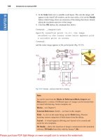
3. Make sure Snap is on by either pressing the F9 key or the Snap Mode
button in the status bar.
<Snap on> will show in the command palette.
4. Move the mouse around the drawing area. The cursors pick box will
jump from point to point at 5 unit intervals. The position of the pick
box will show as coordinate numbers in the status bar (left-hand end).
5. Move the mouse until the coordinate numbers show 60,240,0 and press
the pick button of the mouse (left-click).
6. Move the mouse until the coordinate numbers show 260,240,0 and
left-click.
7. Move the mouse until the coordinate numbers show 260,110,0 and
left-click.
8. Move the mouse until the coordinate numbers show 60,110,0 and
left-click.
9. Move the mouse until the coordinate numbers show 60,240,0 and
left-click. Then press the Return button of the mouse (right-click).
The line rectangle Fig. 2.4 appears in the drawing area.
Introduction to AutoCAD 2011
chapter 2
30
Second example – Line tool (Fig. 2.6)
1. Clear the drawing from the screen with a click on the Close button of
the AutoCAD drawing area. Make sure it is not the AutoCAD 2011
window button.
2. The warning window Fig. 2.5 appears in the centre of the screen. Click
its No button.
60,240,0
60,110,0
260,240,0
260,110,0
Fig. 2.4 First example – Line tool
Fig. 2.5 The AutoCAD warning window
3. Left-click New… button in the File drop-down menu and from the
Select template dialog which appears double-click on acadiso.dwt.
4. Left-click on the Line tool icon and enter figures as follows at each
prompt of the command line sequence:
Command:_line Specify first point: enter 80,235
right-click
Specify next point or [Undo]: enter 275,235
right-click
Specify next point or [Undo]: enter 295,210
right-click
Introducing drawing
chapter 2
31
Specify next point or [Close/Undo]: enter 295,100
right-click
Specify next point or [Close/Undo]: enter 230,100
right-click
Specify next point or [Close/Undo]: enter 230,70
right-click
Specify next point or [Close/Undo]: enter 120,70
right-click
Specify next point or [Close/Undo]: enter 120,100
right-click
Specify next point or [Close/Undo]: enter 55,100
right-click
Specify next point or [Close/Undo]: enter 55,210
right-click
Specify next point or [Close/Undo]: enter c
(Close) right-click
Command:
The result is as shown in Fig. 2.6.
80,235 275,235
55,210 295,210
295,10055,100
120,100
120,70
230,100
230,70
Fig. 2.6 Second example – Line tool
Third example – Line tool (Fig. 2.7)
1. Close the drawing and open a new acadiso.dwt window.
2. Left-click on the Line tool icon and enter figures as follows at each
prompt of the command line sequence:
Command:_line Specify first point: enter 60,210
right-click
Introduction to AutoCAD 2011
chapter 2
32
Specify next point or [Undo]: enter @50,0
right-click
Specify next point or [Undo]: enter @0,20
right-click
Specify next point or [Close/Undo]: enter @130,0
right-click
Specify next point or [Close/Undo]: enter @0,-20
right-click
Third example – Line tool (Fig. 2.7)
1. Close the drawing and open a new acadiso.dwt window.
2. Left-click on the Line tool icon and enter figures as follows at each
prompt of the command line sequence:
Command:_line Specify first point: enter 60,210
right-click
Specify next point or [Undo]: enter @50,0
right-click
Specify next point or [Undo]: enter @0,20
right-click
Specify next point or [Undo/Undo]: enter @130,0
right-click
Specify next point or [Undo/Undo]: enter @0,-20
right-click
Specify next point or [Undo/Undo]: enter @50,0
right-click
Specify next point or [Close/Undo]: enter @0,-105
right-click
Specify next point or [Close/Undo]: enter @-50,0
right-click
Specify next point or [Close/Undo]: enter @0,-20
right-click
Specify next point or [Close/Undo]: enter @-130,0
right-click
Specify next point or [Close/Undo]: enter @0,20
right-click
Specify next point or [Close/Undo]: enter @-50,0
right-click
Specify next point or [Close/Undo]: enter c
(Close) right-click
Command:
The result is as shown in Fig. 2.7.
Introducing drawing
chapter 2
33
60,210
@50,0
@�50,0
@50,0
@�50,0
@0,20
@0,20
@0,�20
@0,�20
@130,0
@�130,0
c (Close) @0,�105
Fig. 2.7 Third example – Line tool
Notes
1. The figures typed at the keyboard determining the corners of the
outlines in the above examples are two-dimensional (2D) x,y
coordinate points. When working in 2D, coordinates are expressed in
terms of two numbers separated by a comma.
2. Coordinate points can be shown in positive or negative numbers.
3. The method of constructing an outline as shown in the first two
examples above is known as the absolute coordinate entry method,
where the x,y coordinates of each corner of the outlines are entered
at the command line as required.
4. The method of constructing an outline as in the third example is
known as the relative coordinate entry method – coordinate points
are entered relative to the previous entry. In relative coordinate entry,
the @ symbol is entered before each set of coordinates with the
following rules in mind:
ve x entry is to the right.
ve x entry is to the left.
ve y entry is upwards.
ve y entry is downwards.
5. The next example (the fourth) shows how lines at angles can
be drawn taking advantage of the relative coordinate entry
method. Angles in AutoCAD are measured in 360 degrees in a
Introduction to AutoCAD 2011
chapter 2
34
counterclockwise (anticlockwise) direction (Fig. 2.8). The symbol
precedes the angle.
Fourth example – Line tool (Fig. 2.9)
1. Close the drawing and open a new acadiso.dwt window.
2. Left-click on the Line tool icon and enter figures as follows at each
prompt of the command line sequence:
Command:_line Specify first point: 70,230
Specify next point: @220,0
Specify next point: @0,-70
Specify next point or [Undo]: @115<225
Specify next point or [Undo]: @-60,0
Specify next point or [Close/Undo]: @115<135
Specify next point or [Close/Undo]: @0,70
Specify next point or [Close/Undo]: c (Close)
Command:
The result is as shown in Fig. 2.9.
180�
135� 45�
225� 315�
0�
90�
270�
Fig. 2.8 The counterclockwise direction of measuring angles in AutoCAD
Introducing drawing
chapter 2
35
Fifth example – Line tool (Fig. 2.10)
Another method of constructing accurate drawings is by using a method
known as tracking. When Line is in use, as each Specify next point:
appears at the command line, a rubber-banded line appears from the last
point entered. Drag the rubber-band line in any direction and enter a
number at the keyboard, followed by a right-click. The line is drawn in the
dragged direction of a length in units equal to the entered number.
In this example because all lines are drawn in vertical or horizontal
directions, either press the F8 key or click the ORTHO button in the status
bar which will only allow drawing horizontally or vertically.
1. Close the drawing and open a new acadiso.dwt window.
2. Left-click on the Line tool icon and enter figures as follows at each
prompt of the command line sequence:
Command:_line Specify first point: enter 65,220
right-click
Specify next point: drag to right enter 240
right-click
Specify next point: drag down enter 145 right-click
Specify next point or [Undo]: drag left enter 65
right-click
Specify next point or [Undo]: drag upwards enter 25
right-click
Specify next point or [Close/Undo]: drag left
enter 120 right-click
Specify next point or [Close/Undo]: drag upwards
enter 25 right-click
@220,0
@60,0
@0,70@0,70
70,230
c(Close)
@115225
@115135
Fig. 2.9 Fourth example – Line tool
Introduction to AutoCAD 2011
chapter 2
36
Specify next point or [Close/Undo]: drag left
enter 55 right-click
Specify next point or [Close/Undo]: c (Close)
right-click
Command:
The result is as shown in Fig. 2.10.
Fig. 2.11 The Circle tool from the Home/Draw panel
240
145
25
120
65
65,220
c (Close)
25
55
Fig. 2.10 Fifth example – Line tool
Drawing with the Circle tool
First example – Circle tool (Fig. 2.13)
1. Close the drawing just completed and open the acadiso.dwt template.
2. Left-click on the Circle tool icon in the Home/Draw panel (Fig. 2.11).
Introducing drawing
chapter 2
37
3. Enter a coordinate and a radius against the prompts appearing in the
command window as shown in Fig. 2.12, followed by right-clicks. The
circle (Fig. 2.13) appears on screen.
180,160
R55
Fig. 2.13 First
example – Circle tool
Fig. 2.12 First example – Circle. The command line prompts when Circle is called
100,160 240,160
R40
R50
R55
Fig. 2.15 Second example
Second example – Circle tool (Fig. 2.15)
1. Close the drawing and open the acadiso.dwt screen.
2. Left-click on the Circle tool icon and construct two circles as shown in
the drawing Fig. 2.14 in the positions and radii shown in Fig. 2.15.
Fig. 2.14 Second example – Circle tool – the two circles of radius 50
Introduction to AutoCAD 2011
chapter 2
38
3. Click the Circle tool again and against the first prompt enter t (the
abbreviation for the prompt tan tan radius), followed by a right-click.
Command_circle Specify center point for circle or
[3P/2P/Ttr (tan tan radius]: enter t right-click
Specify point on object for first tangent of
circle: pick
Specify point on object for second tangent of
circle: pick
Specify radius of circle (50): enter 40 right-
click
Command:
The circle of radius 40 tangential to the two circles already drawn then
appears (Fig. 2.15).
Fig. 2.16 The Erase tool icon from the Home/Modify panel
Notes
1. When a point on either circle is picked a tip (Deferred Tangent)
appears. This tip will only appear when the Object Snap button is
set on with a click on its button in the status bar, or the F3 key of the
keyboard is pressed.
2. Circles can be drawn through 3 points or through 2 points entered at
the command line in response to prompts brought to the command line
by using 3P and 2P in answer to the circle command line prompts.
The Erase tool
If an error has been made when using any of the AutoCAD 2011 tools,
the object or objects which have been incorrectly drawn can be deleted
with the Erase tool. The Erase tool icon can be selected from the Home/
Modify panel (Fig. 2.16) or by entering e at the command line.
Introducing drawing
chapter 2
39
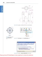
First example – Erase (Fig. 2.18)
1. With Line construct the outline Fig. 2.17.
Select objects Result after Erase
Fig. 2.18 First example – Erase
130
90,255
40
3535 90
Fig. 2.17 First example – Erase. An incorrect outline
2. Assuming two lines of the outline have been incorrectly drawn,
left-click the Erase tool icon. The command line shows:
Command:_erase
Select objects: pick one of the lines 1 found
Select objects: pick the other line 2 total
Select objects: right-click
Command:
And the two lines are deleted (right-hand drawing of Fig. 2.18).
Introduction to AutoCAD 2011
chapter 2
40
Second example – Erase (Fig. 2.19)
The two lines could also have been deleted by the following method:
1. Left-click the Erase tool icon. The command line shows:
Command:_erase
Select objects: enter c (Crossing)
Specify first corner: pick Specify opposite corner:
pick 2 found
Select objects: right-click
Command:
And the two lines are deleted as in the right-hand drawing Fig. 2.19.
opposite corner
first corner
Result after Erase
Fig. 2.19 Second example – Erase
Fig. 2.20 The Undo tool in the Quick Access toolbar
Undo and Redo tools
Two other tools of value when errors have been made are the Undo and
Redo tools. To undo any last action when constructing a drawing, either
left-click the Undo tool in the Quick Access toolbar (Fig. 2.20) or enter
u at the command line. No matter which method is adopted the error is
deleted from the drawing.
Introducing drawing
chapter 2
41
Everything constructed during a session of drawing can be undone by
repeated clicking on the Undo tool icon or by repeatedly entering u’s at
the command line.
To bring back objects that have just been removed by the use of Undo’s,
left-click the Redo tool icon in the Quick Access toolbar (Fig. 2.21) or
enter redo at the command line.
Fig. 2.21 The Redo tool icon in the Quick Access toolbar
Drawing with the Polyline tool
When drawing lines with the Line tool, each line drawn is an object.
A rectangle drawn with the Line tool is four objects. A rectangle drawn
with the Polyline tool is a single object. Lines of different thickness, arcs,
arrows and circles can all be drawn using this tool. Constructions resulting
from using the tool are known as polylines or plines. The tool can be
called from the Home/Draw panel (Fig. 2.22) or by entering pl at the
command line.
Fig. 2.22 The Polyline tool icon in the Home/Draw panel
Introduction to AutoCAD 2011
chapter 2
42
First example – Polyline tool (Fig. 2.23)
In this example enter and right-click have not been included (Fig. 2.23).
Left-click the Polyline tool icon. The command line shows:
Command:_pline Specify start point: 30,250
Current line width is 0
Specify next point or [Arc/Halfwidth/Length/Undo/
Width]: 230,250
Specify next point or [Arc/Close/Halfwidth/Length/
Undo/Width]: 230,120
Specify next point or [Arc/Close/Halfwidth/Length/
Undo/Width]: 30,120
Specify next point or [Arc/Close/Halfwidth/Length/
Undo/Width]: c (Close)
Command:
30,250 230,250
30,120 230,120
Fig. 2.23 First example – Polyline tool
Notes
1. Note the prompts – Arc for constructing pline arcs, Close to close
an outline, Halfwidth to halve the width of a wide pline, Length
to enter the required length of a pline, Undo to undo the last pline
constructed Width to change the width of the pline.
2. Only the capital letter(s) of a prompt needs to be entered in upper or
lower case to make that prompt effective.
3. Other prompts will appear when the Polyline tool is in use as will be
shown in later examples.
Introducing drawing
chapter 2
43
Second example – Polyline tool (Fig. 2.24)
This will be a long sequence, but it is typical of a reasonably complex
drawing using the Polyline tool. In the following sequences, when a
prompt line is to be repeated, the prompts in square brackets ([]) will be
replaced by [prompts] (Fig. 2.24).
40,250 160,250 260,250
260,120
160,120
40,120
260,180
Fig. 2.24 Second example – Polyline tool
Left-click the Polyline tool icon. The command line shows:
Command:_pline Specify start point: 40,250
Current line width is 0
Specify next point or [Arc/Halfwidth/Length/Undo/
Width]: w (Width)
Specify starting width <0>: 5
Specify ending width <5>: right-click
Specify next point or [Arc/Close/Halfwidth/Length/
Undo/Width]: 160,250
Specify next point or [prompts]: h (Halfwidth)
Specify starting half-width <2.5>: 1
Specify ending half-width <1>: right-click
Specify next point or [prompts]: 260,250
Specify next point or [prompts]: 260,180
Specify next point or [prompts]: w (Width)
Specify starting width <1>: 10
Specify ending width <10>: right-click
Specify next point or [prompts]: 260,120
Specify next point or [prompts]: h (Halfwidth)
Specify starting half-width <5>: 2
Specify ending half-width <2>: right-click
Specify next point or [prompts]: 160,120
Specify next point or [prompts]: w (Width)
Introduction to AutoCAD 2011
chapter 2
44
Specify starting width <4>: 20
Specify ending width <20>: right-click
Specify next point or [prompts]: 40,120
Specify starting width <20>: 5
Specify ending width <5>: right-click
Specify next point or [prompts]: c (Close)
Command:
Third example – Polyline tool (Fig. 2.25)
Left-click the Polyline tool icon. The command line shows:
Command:_pline Specify start point: 50,220
Current line width is 0
[prompts]: w (Width)
Specify starting width <0>: 0.5
Specify ending width <0.5>: right-click
Specify next point or [prompts]: 120,220
Specify next point or [prompts]: a (Arc)
Specify endpoint of arc or [prompts]: s (second pt)
Specify second point on arc: 150,200
Specify end point of arc: 180,220
Specify end point of arc or [prompts]: l (Line)
Specify next point or [prompts]: 250,220
Specify next point or [prompts]: 260,190
Specify next point or [prompts]: a (Arc)
Specify endpoint of arc or [prompts]: s (second pt)
Specify second point on arc: 240,170
Specify end point of arc: 250,160
Specify end point of arc or [prompts]: l (Line)
Specify next point or [prompts]: 250,150
Specify next point or [prompts]: 250,120
And so on until the outline Fig. 2.25 is completed.
50,220 120,220 180,220 250,220
50,120
50,190
50,150
250,190
250,150
120,120 180,120
150,200
150,140
240,17060,170
250,120
Fig. 2.25 Third example – Polyline tool
Introducing drawing
chapter 2
45
Fourth example – Polyline tool (Fig. 2.26)
Left-click the Polyline tool icon. The command line shows:
Command:_pline Specify start point: 80,170
Current line width is 0
Specify next point or [prompts]: w (Width)
Specify starting width <0>: 1
Specify ending width <1>: right-click
Specify next point or [prompts]: a (Arc)
Specify endpoint of arc or [prompts]: s (second pt)
Specify second point on arc: 160,250
Specify end point of arc: 240,170
Specify end point of arc or [prompts]: cl (CLose)
Command:
And the circle Fig. 2.26 is formed.
80,170 240,170
160,250
Fig. 2.26 Fourth example – Polyline tool
Fifth example – Polyline tool (Fig. 2.27)
Left-click the Polyline tool icon. The command line shows:
Command:_pline Specify start point: 60,180
Current line width is 0
Specify next point or [prompts]: w (Width)
Specify starting width <0>: 1
Specify ending width <1>: right-click
Specify next point or [prompts]: 190,180
Specify next point or [prompts]: w (Width)
Specify starting width <1>: 20
Specify ending width <20>: 0
Specify next point or [prompts]: 265,180
Specify next point or [prompts]: right-click
Command:
Introduction to AutoCAD 2011
chapter 2
46
And the arrow Fig. 2.27 is formed.
60,180
190,180
265,180
Width=1
Width=20
Width=0
Fig. 2.27 Fifth example – Polyline tool
REVISION NOTES
1. The following terms have been used in this chapter:
Left-click – press the left-hand button of the mouse.
Click – same meaning as left-click.
Double-click – press the left-hand button of the mouse twice.
Right-click – press the right-hand button of the mouse – has the same result as pressing
the Return key of the keyboard.
Drag – move the cursor on to a feature, and holding down the left-hand button of the
mouse pull the object to a new position. Only applies to features such as dialogs and
palettes, not to parts of drawings.
Enter – type the letters of numbers which follow at the keyboard.
Pick – move the cursor on to an item on screen and press the left-hand button of the
mouse.
Return – press the Enter key of the keyboard. This key may also marked with a left facing
arrow. In most cases (but not always) has the same result as a right-click.
Dialog – a window appearing in the AutoCAD window in which settings may be made.
Drop-down menu – a menu appearing when one of the names in the menu bar is clicked.
Tooltip – the name of a tool appearing when the cursor is placed over a tool icon.
Prompts – text appearing in the command window when a tool is selected, which advise
the operator as to which operation is required.
2. Three methods of coordinate entry have been used in this chapter:
Absolute method – the coordinates of points on an outline are entered at the command
line in response to prompts.
Relative method – the distances in coordinate units are entered preceded by @ from the
last point which has been determined on an outline. Angles, which are measured in a
counterclockwise direction, are preceded by .
Tracking – the rubber band of the line is dragged in the direction in which the line is to be
drawn and its distance in units is entered at the command line followed by a right-
click.
Line and Polyline tools – an outline drawn using the Line tool consists of a number of
objects – the number of lines in the outline. An outline drawn using the Polyline is a
single object.
Introducing AutoCAD 2010
chapter 1
47
Introducing drawing
chapter 2
47
Exercises
Methods of constructing answers to the following exercises can be found in the free website:
/>40,250
40,100
270,250
270,100
Fig. 2.28 Exercise 1
7−
"
5
8
4−
"
3
4
Fig. 2.29 Exercise 2
1. Using the Line tool, construct the rectangle
Fig. 2.28.
2. Construct the outline Fig. 2.29 using the Line
tool. The coordinate points of each corner of
the rectangle will need to be calculated from
the lengths of the lines between the corners.
3. Using the Line tool, construct the outline
Fig. 2.30.
140
60
60
60
45�
315�
225�
135�
60
90
Fig. 2.30 Exercise 3
4. Using the Circle tool, construct the two circles
of radius 50 and 30. Then using the Ttr prompt
add the circle of radius 25 (Fig. 2.31).
R50
100,170 200,170
R25
R30
Fig. 2.31 Exercise 4
Introduction to AutoCAD 2010
chapter 1
48
Introduction to AutoCAD 2011
chapter 2
48
5. In an acadiso.dwt screen and using the Circle
and Line tools, construct the line and circle of
radius 40 shown in Fig. 2.32. Then using the
Ttr prompt add the circle of radius 25.
185
R25
50,130
200,190
R40
Fig. 2.32 Exercise 5
R1−
"
5
8
5−
"
1
8
120�
3−
"
7
8
Fig. 2.33 Exercise 6
30 20
260
Polyline width�1.5
80
120 20
20
20
20 20 20
30
Fig. 2.34 Exercise 7
50,210
50,105 250,105
110,105 180,105
250,210
Width�2
Width�10
Width�2
Width�10
Width�2 Width�10
Width�20
Width�30
110,210 180,210
Fig. 2.35 Exercise 8
6. Using the Line tool, construct the two lines
at the length and angle as given in Fig. 2.33.
Then with the Ttr prompt of the Circle tool,
add the circle as shown.
7. Using the Polyline tool, construct the outline given in Fig. 2.34.
8. Construct the outline Fig. 2.35 using the
Polyline tool.
9. With the Polyline tool construct the arrows
shown in Fig. 2.36.
60,200
60,95
295,70
170,140
Endpoint of arc 225, 130
200,200
255,200
Width 20
and 0
Width 25
and 0
Fig. 2.36 Exercise 9
49
AIMS OF THIS CHAPTER
The aims of this chapter are:
1. To give examples of the use of the Arc, Ellipse, Polygon, Rectangle, tools from the
Home/Draw panel.
2. To give examples of the uses of the Polyline Edit (pedit) tool.
3. To introduce the Object Snaps (osnap) and their uses.
4. To introduce the Dynamic Input (DYN) system and its uses.
Chapter 3
Draw tools, Object Snap
and Dynamic Input
Introduction to AutoCAD 2011
chapter 3
50
Introduction
The majority of tools in AutoCAD 2011 can be called into use by any one
of the following six methods:
1. By clicking on the tool’s icon in the appropriate panel. Fig. 3.1 shows
the Polygon tool called from the Home/Draw panel.
Fig. 3.1 The Polygon tool and its tooltip selected from the Home/Draw panel
Fig. 3.2 The tool icons
in the Draw toolbar
2. By clicking on a tool icon in a drop-down menu. Fig. 3.2 shows the
tool names and icons displayed in the Draw drop-down menu. It is
necessary to first bring the menu bar to screen with a click on Show
Menu Bar in the left-click menu of the Quick Access toolbar (Fig. 3.3)
if the menu bar is not already on screen.
3. By entering an abbreviation for the tool name at the command line. For
example, the abbreviation for the Line tool is l, for the Polyline tool it
is pl and for the Circle tool it is c.
4. By entering the full name of the tool at the command line.
5. By making use of the Dynamic Input method of construction.
6. If working in the AutoCAD Classic workspace by selection of tools
from toolbars.
In practice operators constructing drawings in AutoCAD 2011 may well
use a combination of these six methods.
Draw tools, Object Snap and Dynamic Input
chapter 3
51
The Arc tool
In AutoCAD 2011, arcs can be constructed using any three of the
following characteristics of an arc – its Start point, a point on the arc
(Second point), its Center, its End, its Radius, the Length of the arc, the
Direction in which the arc is to be constructed, the Angle between lines of
the arc.
These characteristics are shown in the menu appearing with a click on the
arrow to the right of the Arc tool icon in the Home/Draw panel (Fig. 3.4).
To call the Arc tool click on the flyout of its tool icon in the Home/Draw
panel, click on Arc in the Draw drop-down menu or enter a or arc at the
command line. In the following examples, initials of prompts will be
shown instead of selection from the menu as shown in Fig. 3.5.
Fig. 3.3 Selecting Show Menu Bar from the left-click menu in the Quick Access toolbar