Introduction to AutoCAD 2011- P3 pot
Bạn đang xem bản rút gọn của tài liệu. Xem và tải ngay bản đầy đủ của tài liệu tại đây (2.04 MB, 30 trang )
Draw tools, Object Snap and Dynamic Input
chapter 3
57
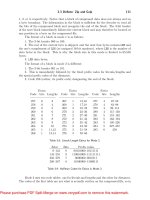
Fig. 3.11 The Drafting Settings dialog with some of the Object Snaps set on
Fig. 3.12 Three Object Snap icons and their tooltips
Introduction to AutoCAD 2011
chapter 3
58
It is sometimes advisable not to have Object Snaps set on in the
Drafting Settings dialog, but to set Object Snap off and use Object
Snap abbreviations at the command line when using tools. The following
examples show the use of some of these abbreviations. Object Snaps can
be toggled on/off by pressing the F3 key of the keyboard.
First example – Object Snap (Fig. 3.13)
Call the Polyline tool:
Command:_pline
Specify start point: 50,230
[prompts]: w (Width)
Specify starting width: 1
Specify ending width <1>: right-click
Specify next point: 260,230
Specify next point: right-click
Command: right-click
PLINE
Specify start point: pick the right-hand end of
the pline
Specify next point: 50,120
Specify next point: right-click
Command: right-click
PLINE
Specify start point: pick near the middle of first
pline
Specify next point: 155,120
Specify next point: right-click
Command: right-click
PLINE
Specify start point: pick the plines at their
intersection
Specify start point: right-click
Command:
The result is shown in Fig. 3.13. In this illustration the Object Snap
tooltips are shown as they appear when each object is added to the outline.
Second example – Object Snap abbreviations
(Fig. 3.14)
Call the Circle tool:
Command:_circle
Specify center point for circle: 180,170
Draw tools, Object Snap and Dynamic Input
chapter 3
59
Specify radius of circle: 60
Command: enter l (Line) right-click
Specify first point: enter qua right-click
of pick near the upper quadrant of the circle
Specify next point: enter cen right-click
of pick near the centre of the circle
Specify next point: enter qua right-click
of pick near right-hand side of circle
Specify next point: right-click
Command:
Fig. 3.13 First example – Osnaps
Notes
With Object Snaps off, the following abbreviations can be used:
end – endpoint;
mid – midpoint;
int – intersection;
cen – centre;
qua – quadrant;
Introduction to AutoCAD 2011
chapter 3
60
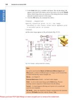
Dynamic Input (DYN)
When Dynamic Input is set on by either pressing the F12 key or with
a click on the Dynamic Input button in the status bar, dimensions,
coordinate positions and commands appear as tips when no tool is in
action (Fig. 3.15).
With a tool in action, as the cursor hairs are moved in response to movement
of the mouse, Dynamic Input tips showing the coordinate figures for the point
Fig. 3.15 The DYN tips appearing when no tool is in action and the cursor is moved
nea – nearest;
ext – extension.(Fig. 3.14)
Center
Quadrant
Quadrant
Fig. 3.14 Second example – Osnaps
Draw tools, Object Snap and Dynamic Input
chapter 3
61
of the cursor hairs will show (Fig. 3.16), together with other details. To see the
drop-down menu giving the prompts available with Dynamic Input press the
down key of the keyboard and clic k the prompt to be used. Fig. 3.16 shows
the Arc prompt as being the next to be used when the Polyline tool is in use.
Fig. 3.16 Coordinate tips when DYN is in action
Notes on the use of Dynamic Input
Although Dynamic Input can be used in any of the AutoCAD 2011
workspaces, some operators may prefer a larger working area. To achieve
this a click on the Clean Screen icon in the bottom right-hand corner
of the AutoCAD 2011 window produces an uncluttered workspace
area. The command palette can be cleared from screen by entering
commandlinehide at the command line. To bring it back press the keys
Ctrl9. These two operations produce a screen showing only title and
status bars (Fig. 3.17). Some operators may well prefer working in such a
larger than normal workspace.
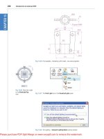
Dynamic Input settings are made in the Dynamic Input sub-dialog of the
Drafting Settings dialog (Fig. 3.18), brought to screen by entering os (or
ds) at the command line.
Introduction to AutoCAD 2011
chapter 3
62
Fig. 3.17 Example of using DYN in a clear screen
Fig. 3.18 Settings for DYN can be made in the Drafting Settings dialog
Draw tools, Object Snap and Dynamic Input
chapter 3
63
When Dynamic Input is in action, tools can be called by using any of the
methods described on page 50.
1. By entering the name of the tool at the command line.
2. By entering the abbreviation for a tool name at the command line.
3. By selecting the tool’s icon from a panel.
4. By selecting the tool’s name from a drop-down menu.
When Dynamic Input is active and a tool is called, command prompts
appear in a tooltip at the cursor position. Fig. 3.19 shows the tooltip
appearing at the cursor position when the Line tool icon in the Home/
Draw panel is clicked.
Fig. 3.19 The prompt appearing on screen when the Line tool is selected
To commence drawing a line, either move the cursor under mouse control
to the desired coordinate point and left-click as in Fig. 3.20, or enter the
required x,y coordinates at the keyboard (Fig. 3.21) and left-click. To
continue drawing with Line drag the cursor to a new position and either
left-click at the position when the coordinates appear as required (Fig. 3.21),
or enter a required length at the keyboard, which appears in the length box
followed by a left-click (Fig. 3.22).
Fig. 3.20 Drag the cursor to the required point and left-click
Fig. 3.21 Enter coordinates for the next point and left-click
Introduction to AutoCAD 2011
chapter 3
64
When using Dynamic Input the selection of a prompt can be made by
pressing the down key of the keyboard (Fig. 3.23) which causes a popup
menu to appear. A click on the required prompt in such a popup menu will
make that prompt active.
Fig. 3.22 Enter length at keyboard and right-click
The down key of the keyboard
Fig. 3.23 The down
key of the keyboard
Fig. 3.24 Selecting
Polyline from the
Home/Draw panel
Fig. 3.25 Dynamic Input – first example – Polyline – the first prompt
Dynamic Input – rst example – Polyline
1. Select Polyline from the Home/Draw panel (Fig. 3.24).
2. To start the construction click at any point on screen. The prompt for
the polyline appears with the coordinates of the selected point showing.
Left-click to start the drawing (Fig. 3.25).
3. Move the cursor and press the down key of the keyboard. A popup
menu appears from which a prompt selection can be made. In the menu
click Width (Fig. 3.26).
4. Another prompt field appears. At the keyboard enter the required width
and right-click. Then left-click and enter ending width or right-click if
the ending width is the same as the starting width (Fig. 3.27).
5. Drag the cursor to the right until the dimension shows the required
horizontal length and left-click (Fig. 3.28).
6. Drag the cursor down until the vertical distance shows and left-click
(Fig. 3.29).
7. Drag the cursor to the left until the required horizontal distance is
showing and right-click (Fig. 3.30).
8. Press the down key of the keyboard and click Close in the menu
(Fig. 3.31). The rectangle completes.
Draw tools, Object Snap and Dynamic Input
chapter 3
65
Fig. 3.26 Dynamic Input – first example – Polyline – click Width in the popup menu
Fig. 3.27 Dynamic Input – first example – Polyline – entering widths
Fig. 3.28 Dynamic Input – first example – Polyline – the horizontal length
Fig. 3.29 Dynamic Input – first example – Polyline – the vertical height
Introduction to AutoCAD 2011
chapter 3
66
Fig. 3.32 shows the completed drawing.
DYN – second example – Zoom
1. Enter Zoom or z at the command line. The first Zoom prompt appears
(Fig. 3.33).
Fig. 3.30 Dynamic Input – first example – Polyline – the horizontal distance
Fig. 3.31 Dynamic Input – first example – Polyline – selecting Close from the popup menu
chapter 3
67
Draw tools, Object Snap and Dynamic Input
2. Right-click and press the down button of the keyboard. The popup list
(Fig. 3.34) appears from which a Zoom prompt can be selected.
3. Carry on using the Zoom tool as described in Chapter 4.
Fig. 3.32 Dynamic Input – first example – Polyline
Fig. 3.33 Dynamic Input – second example – Zoom – enter Zoom at the command line. The
prompts which then appear
Fig. 3.34 Dynamic Input – second example – Zoom – the popup menu appearing with a right-
click and pressing the down keyboard button
DYN – third example – dimensioning
When using DYN, tools can equally as well be selected from a panel.
Fig. 3.35 shows the Linear tool from the Home/Annotation panel
selected when dimensioning a drawing.
Introduction to AutoCAD 2011
chapter 3
68
A prompt appears asking for the first point. Move the cursor to the second
point, another prompt appears (Fig. 3.36). Press the down button of the
keyboard and the popup list (Fig. 3.36) appears from which a selection can
be made.
Fig. 3.35 Selecting Linear from the Home/Annotation panel
Fig. 3.36 Dynamic Input – third example – dimensioning – the popup menu associated with
Linear dimensioning
The Dynamic Input method of constructing 2D drawings can equally as
well be used when constructing 3D solid models drawings (see Chapter 12
onwards).
Why use Dynamic Input?
Some operators may prefer constructing drawings without having to make
entries at the command line in response to tool prompts. By using DYN
drawings, whether in 2D or in 3D format, can be constructed purely from
operating and moving the mouse, entering coordinates at the command
line and pressing the down key of the keyboard when necessary.
Draw tools, Object Snap and Dynamic Input
chapter 3
69
Examples of using other Draw tools
Polygon tool (Fig. 3.37)
Call the Polygon tool – either with a click on its tool icon in the Home/
Draw panel (Fig. 3.1, page 69), from the Draw drop-down menu, or by
entering pol or polygon at the command line. No matter how the tool is
called, the command line shows:
Command:_polygon Enter number of sides <4>: 6
Specify center of polygon or [Edge]: 60,210
Enter an option [Inscribed in circle/Circumscribed
about circle] <I>: right-click (accept Inscribed)
Specify radius of circle: 60
Command:
1. In the same manner construct a 5-sided polygon of centre 200,210 and
of radius 60.
2. Then, construct an 8-sided polygon of centre 330,210 and radius 60.
3. Repeat to construct a 9-sided polygon circumscribed about a circle of
radius 60 and centre 60,80.
4. Construct yet another polygon with 10 sides of radius 60 and of centre
200,80.
5. Finally another polygon circumscribing a circle of radius 60, of centre
330,80 and sides 12.
The result is shown in Fig. 3.37.
Inscribing
circle
5-sided
pentagon
6-sided
hexagon
8-sided
octagon
12-sided
duodecagon
10-sided
decagon
9-sided
nonagon
Circumscribing
circle
Fig. 3.37 First example – Polygon tool
Introduction to AutoCAD 2011
chapter 3
70
Rectangle tool – rst example (Fig. 3.39)
Call the Rectangle tool – either with a click on its tool icon in the Home/
Draw panel (Fig. 3.38) by entering rec or rectangle at the command
line. The tool can be also called from the Draw drop-down menu. The
command line shows (Fig. 3.39):
Fig. 3.38 The
Rectangle tool from
the Home/Draw panel
25,240
20,120
160,30
Width�2
Fileets�R15
Width�4
Chamfers
10 and 15
160,160
200,120
200,240
300,160
315,25
Chamfers
15 and 15
Fig. 3.39 Examples – Rectangle tool
Command:_rectang
Specify first corner point or [Chamfer/
Elevation/Fillet/Thickness/Width]: 25,240
Specify other corner point or [Area/Dimensions/
Rotation]: 160,160
Command:
Rectangle tool – second example (Fig. 3.39)
Command:_rectang
[prompts]: c (Chamfer)
Specify first chamfer distance for rectangles
<0>: 15
Specify first chamfer distance for rectangles <15>:
right-click
Specify first corner point: 200,240
Specify other corner point: 300,160
Command:
Draw tools, Object Snap and Dynamic Input
chapter 3
71
Rectangle tool – third example (Fig. 3.39)
Command: _rectang
Specify first corner point or [Chamfer/Elevation/
Fillet/Thickness/Width]: f (Fillet)
Specify fillet radius for rectangles <0>: 15
Specify first corner point or [Chamfer/Elevation/
Fillet/Thickness/Width]: w (Width)
Specify line width for rectangles <0>: 1
Specify first corner point or [Chamfer/Elevation/
Fillet/Thickness/Width]: 20,120
Specify other corner point or [Area/Dimensions/
Rotation]: 160,30
Command:
Rectangle – fourth example (Fig. 3.39)
Command:_rectang
Specify first corner point or [Chamfer/Elevation/
Fillet/Thickness/Width]: w (Width)
Specify line width for rectangles <0>: 4
Specify first corner point or [Chamfer/Elevation/
Fillet/Thickness/Width]: c (Chamfer)
Specify first chamfer distance for rectangles <0>: 15
Specify second chamfer distance for rectangles
<15>: right-click
Specify first corner point: 200,120
Specify other corner point: 315,25
Command:
The Polyline Edit tool
The Polyline Edit tool is a valuable tool for the editing of polylines.
First example – Polyline Edit (Fig. 3.42)
1. With the Polyline tool construct the outlines 1 to 6 of Fig. 3.40.
2. Call the Edit Polyline tool either from the Home/Modify panel
(Fig. 3.41) or from the Modify drop-down menu, or by entering pe or
pedit at the command line, which then shows:
Command: enter pe
PEDIT Select polyline or [Multiple]: pick pline 2
Introduction to AutoCAD 2011
chapter 3
72
Enter an option [Open/Join/Width/Edit vertex/Fit/
Spline/Decurve/Ltype gen/Reverse/Undo]:
w (Width)
Specify new width for all segments: 2
Enter an option [Open/Join/Width/Edit vertex/Fit/
Spline/Decurve/Ltype gen/Reverse/Undo]: right-
click
Command:
3. Repeat with pline 3 and pedit to Width 10.
4. Repeat with line 4 and enter s (Spline) in response to the prompt line:
Enter an option [Open/Join/Width/Edit vertex/Fit/
Spline/Decurve/Ltype gen/Reverse/Undo]: enter s
5. Repeat with pline 5 and enter j in response to the prompt line:
123
456
Pline rectangel
120�80
Fig. 3.40 Examples – Edit Polyline – the plines to be edited
Fig. 3.41 Calling Edit Polyline from the Home/Modify panel
Draw tools, Object Snap and Dynamic Input
chapter 3
73
Enter an option [Open/Join/Width/Edit vertex/Fit/
Spline/Decurve/Ltype gen/Undo]: enter j
The result is shown in pline 6.
The resulting examples are shown in Fig. 3.42.
Pline 12080
of Width0
Pedit to Width2 Pedit to Width10
Pedit using the
Spline prompt
Pline with open side
Pedit drawing 5
using Close
123
456
Fig. 3.42 Examples – Polyline Edit
Example – Multiple Polyline Edit (Fig. 3.43)
1. With the Polyline tool construct the left-hand outlines of Fig. 3.43.
2. Call the Edit Polyline tool. The command line shows:
20 20 60
80
20 20
15
15
20 30 60 30 20
100
pick
Outlines using
Line and Arc
After Multiple Pedit
to Width=2
Fig. 3.43 Example – Multiple Polyline Edit
Introduction to AutoCAD 2011
chapter 3
74
Command: enter pe
PEDIT Select polyline or [Multiple]: m (Multiple)
Select objects: pick any one of the lines or arcs
of the left-hand outlines of Fig. 6.16 1 found
Select objects: pick another line or arc 1 found 2
total
Continue selecting lines and arcs as shown by the
pick boxes of the left-hand drawing of Fig. 3.45
until the command line shows:
Select objects: pick another line or arc 1 found
24 total
Select objects: right-click
[prompts]: w (Width)
Specify new width for all segments: 1.5
Convert Arcs, Lines and Splines to polylines [Yes/
No]? <Y>: right-click
[prompts]: right-click
Command:
The result is shown in the right-hand drawing of Fig. 3.43.
Transparent commands
When any tool is in operation it can be interrupted by prefixing the
interrupting command with an apostrophe (’). This is particularly useful
when wishing to zoom when constructing a drawing (see page 82). As an
example when the Line tool is being used:
Command:_line
Specify first point: 100,120
Specify next point: 190,120
Specify next point: enter ’z (Zoom)
>> Specify corner of window or [prompts]: pick
>>>> Specify opposite corner: pick
Resuming line command.
Specify next point:
And so on. The transparent command method can be used with any tool.
The set variable PELLIPSE
Many of the operations performed in AutoCAD are carried out under
settings of SET VARIABLES. Some of the numerous set variables
Draw tools, Object Snap and Dynamic Input
chapter 3
75
available in AutoCAD 2011 will be described in later pages. The variable
PELLIPSE controls whether ellipses are drawn as splines or as polylines.
It is set as follows:
Command: enter pellipse right-click
Enter new value for PELLIPSE <0>: enter 1 right-
click
Command:
And now when ellipses are drawn they are plines. If the variable is set to 0,
the ellipses will be splines. The value of changing ellipses to plines is that
they can then be edited using the Polyline Edit tool.
REvISION NOTES
The following terms have been used in this chapter:
Field – a part of a window or of a dialog in which numbers or letters are entered or which can
be read.
Popup list – a list brought in screen with a click on the arrow often found at the right-hand
end of a field.
Object – a part of a drawing which can be treated as a single object. For example, a line
constructed with the Line tool is an object, a rectangle constructed with the Polyline tool
is an object and an arc constructed with the Arc tool is an object. It will be seen in a later
chapter (Chapter 9) that several objects can be formed into a single object.
Ribbon palettes – when working in either of the 2D Drafting and Annotation or of the 3D
Modeling workspace, tool icons are held in panels in the Ribbon.
Command line – a line in the command palette which commences with the word Command.
Snap Mode, Grid Display and Object Snap can be toggled with clicks on their respective
buttons in the status bar. These functions can also be set with function keys: Snap Mode –
F9, Grid Display – F7 and Object Snap – F3.
Object Snaps ensure accurate positioning of objects in drawings.
Object Snap abbreviations can be used at the command line rather than setting in ON in the
Drafting Settings dialog.
Dynamic input allows constructions in any of the three AutoCAD 2011 workspaces or in a full
screen workspace, without having to use the command palette for entering the initials of
command line prompts.
Notes
There are two types of tooltip. When the cursor under mouse control is
paced over a tool icon, the first (a smaller) tooltip is seen. If the cursor
is held in position for a short time the second (a larger) tooltip is seen.
Settings for the tooltip may be made in the Options dialog.
Polygons constructed with the Polygon tool are regular polygons – the
edges of the polygons are all the same length and the angles are of the
same degrees.
Introduction to AutoCAD 2011
chapter 3
76
Polygons constructed with the Polygon tool are plines, so can be edited
by using the Edit Polyline tool.
The easiest method of calling the Edit Polyline tool is to enter pe at the
command line.
The Multiple prompt of the pedit tool saves considerable time when
editing a number of objects in a drawing.
Transparent commands can be used to interrupt tools in operation by
preceding the interrupting tool name with an apostrophe (’).
Ellipses drawn when the variable PELLIPSE is set to 0 are splines;
when PELLIPSE is set to 1, ellipses are polylines. When ellipses are in
polyline form they can be modified using the pedit tool.
Introducing AutoCAD 2010
chapter 1
77
chapter 3
77
Draw tool Object Snap and Dynamic Input
90,210 260,210
260,70
260,9090,90
90,70
260,19090,190
R135
R70
R70
R135
Fig. 3.45 Exercise 2
Exercises
Methods of constructing answers to the following exercises can be found in the free website:
/>1. Using the Line and Arc tools, construct the
outline given in Fig. 3.44.
2. With the Line and Arc tools, construct the
outline Fig. 3.45.
80,250 260,250
260,230
230,160
260,90
260,70
Fig. 3.44 Exercise 1
3. Using the Ellipse and Arc tools, construct the
drawing Fig. 3.46.
80,230
290,230
290,75
80,75
R130
R130
40
Fig. 3.46 Exercise 3
4. With the Line, Circle and Ellipse tools,
construct Fig. 3.47.
R−
"
3
8
−
"
7
8
−
"
3
4
9−
"
1
2
5−
"
7
8
Fig. 3.47 Exercise 4
Introduction to AutoCAD 2010
chapter 1
78
Introduction to AutoCAD 2011
chapter 3
78
250,250
250,110
110,250
110,110
Each ellipse minor axis=30
Fig. 3.48 Exercise 5
5. With the Ellipse tool, construct the drawing
Fig. 3.48.
6. Fig. 3.49 shows a rectangle in the form of a
square with hexagons along each edge. Using
the Dimensions prompt of the Rectangle
tool, construct the square. Then, using the
Edge prompt of the Polygon tool, add
the four hexagons. Use the Object Snap
endpoint to ensure the polygons are in their
exact positions.
65
65
Fig. 3.49 Exercise 6
7. Fig. 3.50 shows seven hexagons with edges
touching. Construct the inner hexagon using
the Polygon tool, then with the aid of the
Edge prompt of the tool, add the other six
hexagons.
30
Fig. 3.50 Exercise 7
8. Fig. 3.51 was constructed using only the
Rectangle tool. Make an exact copy of the
drawing using only the Rectangle tool.
4−
"
1
8
−
"
5
8
2"
2"
2−
"
3
4
Fig. 3.51 Exercise 8
Introducing AutoCAD 2010
chapter 1
79
Draw tool Object Snap and Dynamic Input
chapter 3
79
9. Construct the drawing Fig. 3.52 using the
Line and Arc tools. Then, with the aid of the
Multiple prompt of the Edit Polyline tool,
change the outlines into plines of Width1.
R60
160
120
80
60
100
60
40
Fig. 3.52 Exercise 9
10. Construct Fig. 3.53 using the Line and Arc
tools. Then change all widths of lines and arcs
to a width of 2 with Polyline Edit.
17060
40
60
50
40
10
Fig. 3.53 Exercise 10
11. Construct Fig. 3.54 using the Rectangle, Line and Edit Polyline tools.
6060
130
23060 60
Inner pline of Width10
Outer pline of Width5
Chamfers 2020
30
Fig. 3.54 Exercise 11
81
AIMS OF THIS CHAPTER
The aims of this chapter are:
1. To demonstrate the value of the Zoom tools.
2. To introduce the Pan tool.
3. To describe the value of using the Aerial View window in conjunction with the Zoom
and Pan tools.
4. To update the acadiso.dwt template.
5. To describe the construction and saving of drawing templates.
Chapter 4
Zoom, Pan and
templates
Introduction to AutoCAD 2011
chapter 4
82
Introduction
The use of the Zoom tools allows not only the close inspection of the most
minute areas of a drawing in the AutoCAD 2011 drawing area, but also the
accurate construction of very small details in a drawing.
The Zoom tools can be called by selection from the View/Navigate panel
or from the View drop-down menu (Fig. 4.1). However by far the easiest
and quickest method of calling the Zoom is to enter z at the command line
as follows:
Command: enter z right-click
ZOOM Specify corner of window, enter a scale factor
(nX or nXP) or [All/Center/Dynamic/Extents/
Previous/Scale/Window/Object] <real time>:
Fig. 4.1 Calling Zoom – from the Zoom/Navigate panel or from the View drop-down menu
This allows the different zooms:
Realtime – selects parts of a drawing within a window.
All – the screen reverts to the limits of the template.