Introduction to AutoCAD 2011- P5 ppsx
Bạn đang xem bản rút gọn của tài liệu. Xem và tải ngay bản đầy đủ của tài liệu tại đây (1.58 MB, 30 trang )
Introduction to AutoCAD 2011
chapter 5
118
The Join tool
The Join tool can be used to join plines providing their ends are touching,
to join lines which are in line with each other, and to join arcs and convert
arcs to circles.
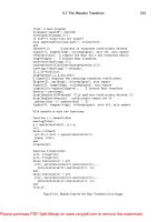
Examples – Join (Fig. 5.38)
1. Construct a rectangle from four separate plines – drawing 1 of
Fig. 5.38; construct two lines – drawing 2 of Fig. 5.38 and an arc –
drawing 3 of Fig. 5.38.
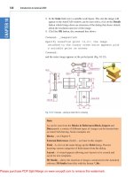
2. Call the Join tool – either click the Join tool icon in the Home/Modify
panel (Fig. 5.37), select Join from the Modify drop-down menu or
enter join or j at the command line. The command line shows:
Fig. 5.37 The Join tool icon from the Home/Modify panel
Note
Remember the default rotation of AutoCAD 2011 is counterclockwise.
This applies to the use of the Break tool.
Command: _join Select source object:
Select objects to join to source: pick a pline 1
found
Select objects to join to source: pick another 1
found, 2 total
Select objects to join to source: pick another 1
found, 3 total
Select objects to join to source: right-click
The Modify tools
chapter 5
119
3 segments added to polyline
Command: right-click
JOIN Select source object: pick one of the lines
Select lines to join to source: pick the other 1
found
Select lines to join to source: right-click
1 line joined to source
Command: right-click
JOIN Select source object: pick the arc
Select arcs to join to source or [cLose]: enter l
right-click
Arc converted to a circle.
Command:
The results are shown in Fig. 5.38.
1
2
3
Result 1
a closed polyline
Result 2
Result 3
4 separate plines
Fig. 5.38 Examples – Join
The Extend tool
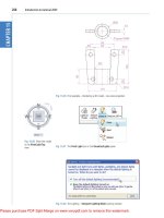
Examples – Extend (Fig. 5.40)
1. Construct plines and a circle as shown in the left-hand drawings of Fig.
5.40.
2. Call Extend – either click the Extend tool icon in the Home/Modify
panel (Fig. 5.39), pick Extend from the Modify drop-down menu or
enter ex or extend at the command line which then shows:
Command:_extend
Current settings: Projection=UCS Edge=Extend
Select
boundary edges . . .
Introduction to AutoCAD 2011
chapter 5
120
Select objects or <select all>: pick 1 found
Select objects: right-click
Select object to extend or shift-select to trim
or[Fence/Crossing/Project/Edge/Undo]: pick
Repeat for each object to be extended. Then:
Select object to extend or shift-select to trim or
[Fence/Crossing/Project/Edge/Undo]: right-click
Command:
The results are shown in Fig. 5.40.
Fig. 5.39 The Extend tool icon from the Home/Modify panel
Results
boundary edge
objects to
extend
objects to
extend
Fig. 5.40 Examples – Extend
The Modify tools
chapter 5
121
The Fillet and Chamfer tools
These two tools can be called from the Home/Modify panel. There
are similarities in the prompt sequences for these two tools. The major
differences are that only one (Radius) setting is required for a fillet, but
two (Dist1 and Dist2) are required for a chamfer. The basic prompts for
both are:
Fillet
Command:_fillet
Current
settings: Mode = TRIM, Radius = 1
Select first object or [Polyline/Radius/Trim/
mUltiple]: enter r (Radius)right-click
Specify fillet radius <1>: 15
Chamfer
Command:_chamfer
(TRIM mode) Current chamfer Dist1 = 1, Dist2 = 1
Select first line or [Undo/Polyline/Distance/Angle/
Trim/mEthod/Multiple]: enter d (Distance)
right-click
Specify first chamfer distance <1>: 10
Specify second chamfer distance <10>: right-click
Examples – Fillet (Fig. 5.42)
1. Construct three rectangles 100 by 60 using either the Line or the
Polyline tool (Fig. 5.42).
2. Call Fillet – click the arrow to the right of the tool icon in the Home/
Modify panel and select Fillet from the menu which appears
(Fig. 5.41), pick Fillet from the Modify drop-down menu or enter f or
fillet at the command line which then shows:
Command:_fillet
Current
settings: Mode = TRIM, Radius = 1
Note
Observe the similarity of the Extend and No extend prompts with those
of the Trim tool.
Introduction to AutoCAD 2011
chapter 5
122
Select first object or [Polyline/Radius/Trim/
mUltiple]: r (Radius)
Specify fillet radius <0>: 15
Select first object or [Undo/Polyline/Radius/Trim/
Multiple]: pick
Select second object or shift-select to apply
corner: pick
Command:
Three examples are given in Fig. 5.42.
Original
rectangle
10060
Radius10
Radius20
Radius15
No trim
Fig. 5.42 Examples – Fillet
Fig. 5.41 Select Fillet from the menu in the Home/Modify panel
Examples – Chamfer (Fig. 5.44)
1. Construct three rectangles 100 by 60 using either the Line or the
Polyline tool.
2. Call Chamfer – click the arrow to the right of the tool icon in the
Home/Modify panel and select Chamfer from the menu which appears
The Modify tools
chapter 5
123
(Fig. 5.43), pick Chamfer from the Modify drop-down menu or enter
cha or chamfer at the command line which then shows:
Fig. 5.43 Select Chamfer from the Home/Modify panel
Dist1=10
Dist2=10
Dist1=10
Dist2=15
Dist1=20
Dist2=20
No trim
Original
rectangle
100x60
Fig. 5.44 Examples – Chamfer
Command:_chamfer
(TRIM mode) Current chamfer Dist1 = 1, Dist2 = 1
Select first line or [Undo/Polyline/Distance/Angle/
Trim/
mEthod/Multiple]: d
Specify first chamfer distance <1>: 10
Specify second chamfer distance <10>: right-click
Select first line or [Undo/Polyline/Distance/Angle/
Trim/mEthod/Multiple]:pick the first line for the
chamfer
Select second line or shift-select to apply
corner: pick
Command:
The result is shown in Fig. 5.44. The other two rectangles are chamfered in
a similar manner except that the No trim prompt is brought into operation
with the bottom left-hand example.
Introduction to AutoCAD 2011
chapter 5
124
REVISION NOTES
1. The Modify tools are among the most frequently used tools in AutoCAD 2011.
2. The abbreviations for the Modify tools are:
Copy – cp or co
Mirror – mi
Offset – o
Array – ar
Move – m
Rotate – ro
Scale – sc
Stretch – s
Trim – tr
Extend – ex
Break – br
Join – j
Chamfer – cha
Fillet – f
3. There are two other tools in the 2D Draw control panel: Erase – some examples were
given in Chapter 2 – and Explode – further details of this tools will be given in Chapter 9.
A note – selection windows and crossing windows
In the Options dialog settings can be made in the Selection sub-dialog for Visual Effects. A
click on the Visual Effects Settings… button brings up another dialog. If the Area Selection
Effect settings are set, on a normal window from top left to bottom right will colour in a
chosen colour (default blue). A crossing window from bottom left to top right, will be coloured
red. Note also that highlighting – selection Preview Effect allows objects to highlight if this
feature is on. These settings are shown in Fig. 5.45.
Fig. 5.45 Visual Setting Effects Settings sub-dialog of the Options dialog
The Modify tools
chapter 5
125
4. When using Mirror, if text is part of the area to be mirrored, the set variable Mirrtext will
require setting – to either 1 or 0.
5. With Offset the Through prompt can be answered by clicking two points in the drawing
area the distance of the desired offset distance.
6. Polar Arrays can be arrays around any angle set in the Angle of array field of the Array
dialog.
7. When using Scale, it is advisable to practise the Reference prompt.
8. The Trim tool in either its Trim or its No trim modes is among the most useful tools in
AutoCAD 2011.
9. When using Stretch circles are unaffected by the stretching.
10. There are some other tools in the Home/Modify panel not described in this book. The
reader is invited to experiment with these other tools. They are:
Bring to Front, Send to Back, Bring above Objects, Send under Objects;
Set by Layer; Change Space; Lengthen; Edit Spline, Edit Hatch; Reverse.
REVISION NOTES CONTINUED
Introduction to AutoCAD 2010
chapter 1
126
Introduction to AutoCAD 2011
chapter 5
126
Exercises
Methods of constructing answers to the following exercises can be found in the free website:
/>1. Construct the Fig. 5.46. All parts are plines of width 0.7 with corners lleted R10. The long strips have
been constructed using Circle, Polyline, Trim and Polyline Edit. Construct one strip and then copy it
using Copy.
2. Construct the drawing Fig. 5.47. All parts of the drawing are plines of width 0.7. The setting in the
Array dialog is to be 180 in the Angle of array eld.
160
2040
230120
80
10
100
R10
All fillets R10
Fig. 5.46 Exercise 1
Ø
−
"
3
4
R
−
"
3
4
9−
"
7
8
7−
"
1
2
1−
"
1
8
1−
"
1
8
Fig. 5.47 Exercise 2
Introducing AutoCAD 2010
chapter 1
127
The Modify tools
chapter 5
127
3. Using the tools Polyline, Circle, Trim,
Polyline Edit, Mirror and Fillet construct the
drawing (Fig. 5.48).
4. Construct the circles and lines (Fig. 5.49).
Using
Oset and the Ttr prompt of the Circle
tool followed by Trim, construct one of the
outlines arrayed within the outer circle. Then,
with Polyline Edit change the lines and arcs
into a pline of width 0.3. Finally array the
outline 12 times around the centre of the
circles (Fig. 5.50).
80 30
20
10
R15
Ø20
Fig. 5.51 Exercise 5
Chamfers 20x10
170
100
R7.5
10
30
25
25
Fig. 5.52 Exercise 6
5. Construct the arrow (Fig. 5.51). Array the
arrow around the centre of its circle 8 times to
produce the right-hand drawing of Fig. 5.51.
6. Construct the left-hand drawing of Fig. 5.52.
Then with Move, move the central outline to
the top left-hand corner of the outer outline.
Then with Copy make copies to the other
corners.
Ø50
Ø80
30°
Ø200
Ø220
Fig. 5.49 Exercise 4 – circles and lines on which the
exercise is based
Offset 5
R5
R10
Fig. 5.50 Exercise 4
Fig. 5.48 Exercise 3
260
160
30
R15
R20
R20
R20
10
10
140
80
Introduction to AutoCAD 2010
chapter 1
128
Introduction to AutoCAD 2011
chapter 5
128
7. Construct the drawing Fig. 5.53 and make two copies using Copy. With Rotate rotate each of the
copies to the angles as shown.
Rotated 330° Rotated 315°
−
"
3
4
R
−
"
3
4
R
−
"
3
4
R
−
"
3
8
1−
"
1
4
5−
"
1
8
Ø
1−
"
1
8
Ø
1−
"
1
8
Fig. 5.53 Exercise 7
R20
1590
35
R20
Ø60
Ø30
20
Scale 0.5
Rotate 300°
Scale 2
R20
Fig. 5.54 Exercise 8
8. Construct the dimensioned drawing of Fig. 5.54. With Copy copy the drawing. Then with Scale scale
the drawing to scale of 0.5, followed by using Rotate to rotate the drawing through an angle of as
shown. Finally scale the original drawing to a scale of 2:1.
Introducing AutoCAD 2010
chapter 1
129
The Modify tools
chapter 5
129
9. Construct the left-hand drawing of Fig. 5.55. Include the dimensions in your drawing. Then, using the Stretch
tool, stretch the drawing, including its dimensions to the sizes as shown in the right-hand. The dimensions are
said to be associative (see Chapter 6).
1
2
5−
"
7
8
1−
"
1
8
2−
"
7
8
4−
"
3
8
3−
"
7
8
5−
"
1
2
4−
"
1
2
6−
"
7
8
Fig. 5.55 Exercise 9
Polar Array
16 times in
angle 180°
R90
R10
10
Fig. 5.56 Exercise 10
10. Construct the drawing Fig. 5.56. All parts of the drawing are plines of width 0.7. The setting in the
Array dialog is to be 180 in the Angle of array eld.
131
AIMS OF THIS CHAPTER
The aims of this chapter are:
1. To describe a variety of methods of dimensioning drawings.
2. To describe methods of adding text to drawings.
Chapter 6
Dimensions and Text
Introduction to AutoCAD 2011
chapter 6
132
Introduction
The dimension style (My_style) has already been set in the acadiso.dwt
template, which means that dimensions can be added to drawings using
this dimension style.
The Dimension tools
There are several ways in which the dimensions tools can be called.
1. From the Annotate/Dimensions panel (Fig. 6.1).
Fig. 6.1 Dimension tools in the Annotate/
Dimensions panel
Fig. 6.2 Dimensions in the drop-down menu
2. Click Dimension in the menu bar. Dimension tools can be selected
from the drop-down menu which appears (Fig. 6.2).
3. By entering an abbreviation for a dimension tool at the command line.
Some operators may well decide to use a combination of the three methods.
4. In the Classic AutoCAD workspace from the Dimension toolbar.
Dimensions and Text
chapter 6
133
Adding dimensions using these tools
First example – Linear Dimension (Fig. 6.4)
1. Construct a rectangle 180 110 using the Polyline tool.
2. Make the Dimensions layer current from the Home/Layers panel
(Fig. 6.3).
Note
In general, in this book dimensions are shown in drawings in the Metric
style – mainly in millimetres, but some will be shown in Imperial
style – in inches. To see how to set a drawing template for Imperial
dimensioning see Chapter 4 (page 95).
Fig. 6.3 The Home/Layers panel – making Dimensions layer current
3. Click the Linear tool icon in the Annotate/Dimension panel (Fig. 6.1).
The command line shows:
Command: _dimlinear
Specify first extension line origin or <select
object>: pick
Specify second extension line origin: pick
Specify dimension line location or [Mtext/
Text/Angle/Horizontal/Vertical/Rotated]: pick
Dimension
text = 180
Command:
Fig. 6.4 shows the 180 dimension. Follow exactly the same procedure for
the 110 dimension.
Introduction to AutoCAD 2011
chapter 6
134
Second example – Aligned Dimension (Fig. 6.5)
1. Construct the outline Fig. 6.5 using the Line tool.
170
99
50
170
139
Fig. 6.5 Second example – Aligned dimension
180
110
First
extension
line
Second
extension
line
Dimension line location
Fig. 6.4 First example – Linear dimension
Notes
1. If necessary use Osnaps to locate the extension line locations.
2. At the prompt:
Specify first extension line origin or [select
object]:
Also allows the line being dimensioned to be picked.
3. The drop-down menu from the Line tool icon contains the following
tool icons – Angular, Linear, Aligned, Arc Length, Radius,
Diameter, Jog Line and Ordinate. Refer to Fig. 6.1 when working
through the examples below. Note – when a tool is chosen from this
menu, the icon in the panel changes to the selected tool icon.
Dimensions and Text
chapter 6
135
2. Make the Dimensions layer current (Home/Layers panel).
3. Left-click the Aligned tool icon (see Fig. 6.1) and dimension the
outline. The prompts and replies are similar to the first example.
Third example – Radius Dimension (Fig. 6.6)
1. Construct the outline Fig. 6.5 using the Line and Fillet tools.
2. Make the Dimensions layer current (Home/Layers panel).
3. Left-click the Radius tool icon (see Fig. 6.1). The command line shows:
Command:_dimradius
Select arc or circle: pick one of the arcs
Dimension
text = 30
Specify dimension line location or [Mtext/Text/
Angle]: pick
Command:
4. Continue dimensioning the outline as shown in Fig. 6.6.
R30
190
100
R20
Fig. 6.6 Third example – Radius dimension
Notes
1. At the prompt:
[Mtext/Text/Angle]:
If a t (Text) is entered, another number can be entered, but remember
if the dimension is a radius the letter R must be entered as a prefix to
the new number.
2. If the response is a (Angle), and an angle number is entered the text
for the dimension will appear at an angle.
3. If the response is m (Mtext) the Text Formatting dialog appears
together with a box in which new text can be entered. See page 147.
4. Dimensions added to a drawing using other tools from the Annotate/
Dimensions panel should be practised.
Introduction to AutoCAD 2011
chapter 6
136
Adding dimensions from the command line
From Figs 6.1 and 6.2 it will be seen that there are some dimension tools
which have not been described in examples. Some operators may prefer
entering dimensions from the command line. This involves abbreviations
for the required dimension such as:
For Linear Dimension – hor (horizontal) or ve (vertical);
For Aligned Dimension – al;
For Radius Dimension – ra;
For Diameter Dimension – d;
For Angular Dimension – an;
For Dimension Text Edit – te;
For Quick Leader – l.
And to exit from the dimension commands – e (Exit).
First example – hor and ve (horizontal and
vertical) – Fig. 6.8
1. Construct the outline Fig. 6.7 using the Line tool. Its dimensions are
shown in Fig. 6.8.
Fig. 6.7 First example – outline to dimension
2. Make the Dimensions layer current (Home/Layers panel).
3. At the command line enter dim. The command line will show:
Command: enter dim right-click
Dim: enter hor (horizontal) right-click
Specify first extension line origin or <select
object>: pick
Specify second extension line origin: pick
Non-associative dimension created.
Specify dimension line location or [Mtext/Text/
Angle]: pick
Enter dimension text <50>: right-click
Dimensions and Text
chapter 6
137
Dim: right-click
HORIZONTAL
Specify first extension line origin or <select
object>: pick
Specify second extension line origin: pick
Non-associative dimension created.
Specify dimension line location or [Mtext/Text/
Angle/Horizontal/Vertical/Rotated]: pick
Enter dimension text <140>: right-click
Dim: right-click
And the 50 and 140 horizontal dimensions are added to the outline.
4. Continue to add the right-hand 50 dimension. Then when the command
line shows:
Dim: enter ve (vertical) right-click
Specify first extension line origin or <select
object>: pick
Specify second extension line origin: pick
Specify dimension line location or [Mtext/Text/
Angle/Horizontal/Vertical/Rotated]: pick
Dimension text <20>: right-click
Dim: right-click
VERTICAL
Specify first extension line origin or <select
object>: pick
Specify second extension line origin: pick
Specify dimension line location or [Mtext/Text/
Angle/Horizontal/Vertical/Rotated]: pick
Dimension text <100>: right-click
Dim: enter e (Exit) right-click
Command:
The result is shown in Fig. 6.8.
50 140 50
100 20
Fig. 6.8 First example – horizontal and vertical dimensions
Introduction to AutoCAD 2011
chapter 6
138
Second example – an (Angular) – Fig. 6.10
1. Construct the outline Fig. 6.9 – a pline of width 1.
90
6060
290
90°
Select line Select second line
135°
135°
Fig. 6.10 Second example – an (Angular) dimension
4090
406060
290
45
Fig. 6.9 Second example – outline for dimensions
2. Make the Dimensions layer current (Home/Layers panel).
3. At the command line:
Command: enter dim right-click
Dim: enter an right-click
Select arc, circle, line or <specify vertex>: pick
Select second line: pick
Specify dimension arc line location or [Mtext/
Text/Angle/Quadrant]: pick
Enter dimension <90>: right-click
Enter text location (or press ENTER): pick
Dim:
And so on to add the other angular dimensions.
The result is given in Fig. 6.10.
Dimensions and Text
chapter 6
139
Third example – l (Leader) – Fig. 6.12
1. Construct Fig. 6.11.
125
45
70
CHA 10x10
CHA 15x15
CHA 30x30
CHA 20x20
Fig. 6.12 Third example – l (Leader) dimensions
10
1012520
30
15
45
15
30 20
70
Fig. 6.11 Third example – outline for dimensioning
2. Make the Dimensions layer current (Home/Layers panel).
3. At the command line:
Command: enter dim right-click
Dim: enter l (Leader) right-click
Leader start: enter nea (osnap nearest)
right-click to pick one of the chamfer
lines
To point: pick
To point: pick
To point: right-click
Dimension text <0>: enter
CHA 10 × 10 right-click
Dim: right-click
Continue to add the other leader dimensions – Fig. 6.12.
Introduction to AutoCAD 2011
chapter 6
140
2. Make the Dimensions layer current (Home/Layers panel).
3. At the command line:
Command: enter dim right-click
Dim: enter te (tedit) right-click
Select dimension: pick the dimension to be changed
Specify new location for text or [Left/Right/
Center/Home/Angle]: either pick or enter a prompt
capital letter
Dim:
The results as given in Fig. 6.14 show dimensions which have been moved.
The 210 dimension changed to the left-hand end of the dimension line, the
130 dimension changed to the left-hand end of the dimension line and the
30 dimension position changed.
Polygon
Ellipse 30�20
210
30
∆20
20 20
20 20
130
30
Fig. 6.14 Fourth example – dimensions amended with tedit
Polygon
20 2030
210
Ellipse 30�20
30
130
20 20
∆20
Fig. 6.13 Fourth example – dimensioned drawing
Fourth example – te (dimension text edit) – Fig. 6.14
1. Construct Fig. 6.13.
Dimensions and Text
chapter 6
141
2. Make the Dimensions layer current (Home/Layers panel).
3. Call the Arc Length tool from the Annotate/Dimensions panel (see
Fig. 6.3) or enter dimarc at the command line. The command line shows:
Command: _dimarc
Select arc or polyline arc segment: pick an arc
Specify arc length dimension location, or [Mtext/
Text/Angle/Partial/Leader]: pick a suitable
position
Dimension
text = 147
Command:
Examples on two arcs are shown in Fig. 6.15.
The Jogged tool (Fig. 6.16)
1. Draw a circle and an arc as indicated in Fig. 6.16.
147
62
213
Fig. 6.15 Examples – Arc Length tool
The Arc Length tool (Fig. 6.15)
1. Construct two arcs of different sizes as in Fig. 6.15.
R49
R60
R60
Fig. 6.16 Examples – the Jogged tool
Introduction to AutoCAD 2011
chapter 6
142
2. Make the Dimensions layer current (Home/Layers panel).
3. Call the Jogged tool, either with a left-click on its tool icon in the
Annotation/Dimension panel (see Fig. 6.1) or by entering jog at the
command line. The command line shows:
Command: _dimjogged
Select arc or circle: pick the circle or the
arc
Specify center location override:
pick
Dimension
text = 60
Specify dimension line location or [Mtext/Text/
Angle]: pick
Specify jog location: pick
Command:
The results of placing as jogged dimension on a circle and an arc are
shown in Fig. 6.16.
Dimension tolerances
Before simple tolerances can be included with dimensions, new settings
will need to be made in the Dimension Style Manager dialog as
follows:
1. Open the dialog. The quickest way of doing this is to enter d at the
command line followed by a right-click. This opens up the dialog.
2. Click the Modify… button of the dialog, followed by a left-click on
the Primary Units tab and in the resulting sub-dialog make settings
as shown in Fig. 6.17. Note the changes in the preview box of the
dialog.
Example – tolerances (Fig. 6.19)
1. Construct the outline Fig. 6.18.
2. Make the Dimensions layer current (Home/Layers panel).
3. Dimension the drawing using either tools from the Dimension panel
or by entering abbreviations at the command line. Because tolerances
have been set in the Dimension Style Manager dialog (Fig. 6.17), the
toleranced dimensions will automatically be added to the drawing
(Fig. 6.19).
Dimensions and Text
chapter 6
143
Fig. 6.17 The Tolerances sub-dialog of the Modify Dimension Style dialog
Ø40.00
0.05
0.05
65.00
0.05
0.05
55.00
0.05
0.05
245.00
0.05
0.05
115.00
0.05
0.05
The dimensions in this drawing show tolerances
Fig. 6.19 Example – tolerances
Fig. 6.18 First example – simple tolerances – outline