Introduction to AutoCAD 2011- P7 pot
Bạn đang xem bản rút gọn của tài liệu. Xem và tải ngay bản đầy đủ của tài liệu tại đây (4.47 MB, 30 trang )
Blocks and Inserts
chapter 9
179
The Block Definition dialog (Fig. 9.3) appears. To make a block from
the Compass symbol drawing.
a. Enter compass in the Name field.
b. Click the Select Objects button. The dialog disappears. Window the
drawing of the compass. The dialog reappears. Note the icon of the
compass at the top-centre of the dialog.
c. Click the Pick Point button. The dialog disappears. Click a point on
the compass drawing to determine its insertion point. The dialog
reappears.
d. If thought necessary enter a description in the Description field of
the dialog.
e. Click the OK button. The drawing is now saved as a block in the
drawing.
Fig. 9.3 The Block Definition dialog with entries for the compass block
3. Repeat items 1 and 2 to make blocks of all the other symbols in the
drawing.
4. Open the Block Definition dialog again and click the arrow on the right
of the Name field. Blocks saved in the drawing are listed (Fig. 9.4).
Inserting blocks into a drawing
There are two methods by which symbols saved as blocks can be inserted
into another drawing.
Example – rst method of inserting blocks
Ensure that all the symbols saved as blocks using the Create tool are saved
in the data of the drawing in which the symbols were constructed. Erase all
Introduction to AutoCAD 2011
chapter 9
180
of the drawings of the symbols and in their place construct the outline of
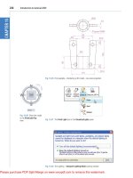
the plan of a bungalow to a scale of 1:50 (Fig. 9.5). Then:
1. Left-click the Insert tool icon in the Home/Block panel (Fig. 9.6) or
the Insert Block tool in the Draw toolbar. The Insert dialog appears
on screen (Fig. 9.7). From the Name popup list select the name of the
block which is to be inserted, in this example the 2.5 window.
2. Click the dialog’s OK button, the dialog disappears. The symbol drawing
appears on screen with its insertion point at the intersection of the cursor
hairs ready to be dragged into its position in the plan drawing.
3. Once all the block drawings are placed, their positions can be adjusted.
Blocks are single objects and can thus be dragged into new positions as
16 m
12 m
4 m
7 m
Fig. 9.5 First example – inserting blocks. Outline plan
Fig. 9.4 The popup list in the Name field of the Block Definition dialog
Blocks and Inserts
chapter 9
181
required under mouse control. Their angle of position can be amended
at the command line, which shows:
Command:_insert
Specify insertion point or [Basepoint/Scale/
Rotate]: pick
Command:
Selection from these prompts allows scaling or rotating as the block is
inserted.
4. Insert all necessary blocks and add other detail as required to the plan
outline drawing. The result is given in Fig. 9.8.
Example – second method of inserting blocks
1. Save the drawing with all the blocks to a suitable file name. Remember
this drawing includes data of the blocks in its file.
2. Left-clic k DesignCenter in the View/Palettes panel (Fig. 9.9) or press the
Ctrl2 keys. The DesignCenter palette appears on screen (Fig. 9.10).
3. With the outline plan (Fig. 9.5) on screen the symbols can all be
dragged into position from the DesignCenter.
Fig. 9.6 The Insert tool icon in the Home/Block panel
Fig. 9.7 The Insert dialog with its Name popup list showing all the blocks
Introduction to AutoCAD 2011
chapter 9
182
Fig. 9.8 Example – first method of inserting blocks
Fig. 9.9 Selecting DesignCenter from the View/Palettes panel
Fig. 9.10 The DesignCenter with the compass block dragged on screen
Blocks and Inserts
chapter 9
183
Notes about the DesignCenter palette
1. As with other palettes, the DesignCenter palette can be resized by
dragging the palette to a new size from its edges or corners.
2. Clicks on one of the three icons at the top-right corner of the palette
(Fig. 9.11) have the following results**.
Tree View Toggle – changes from showing two areas – a Folder List
and icons of the blocks within a file – to a single area showing the
block icons (Fig. 9.12).
Preview – a click on the icon opens a small area at the base of the
palette open showing an enlarged view of the selected block icon.
Description – a click on the icon opens another small area with a
description of the block.
A block is a single object no matter from how many objects it was
originally constructed. This enables a block to be dragged about the
drawing area as a single object.
Fig. 9.11 The icons at the top of the DesignCenter palette
Fig. 9.12 The results of a click on Tree View Toggle
Introduction to AutoCAD 2011
chapter 9
184
The Explode tool
A check box in the bottom left-hand corner of the Insert dialog is labelled
Explode. If a tick is in the check box, Explode will be set on and when
a block is inserted it will be exploded into the objects from which it was
constructed (Fig. 9.13).
Another way of exploding a block would be to use the Explode tool from
the Home/Modify panel (Fig. 9.14). A click on the icon or entering ex at
the command line brings prompts into the command line:
Command: _explode
Select
objects: <Object Snap Tracking on> pick a
block on screen 1 found
Select objects: right-click
Command:
And the picked object is exploded into its original objects.
Fig. 9.13 The Explode
check box in the Insert
dialog
Fig. 9.14 The Explode tool icon in the Home/Modify panel
Purge
The Purge dialog (Fig. 9.15) is called to screen by entering pu or purge at
the command line.
Purge can be used to remove data (if any is to be purged) from within a
drawing, thus saving file space when a drawing is saved to disk.
To purge a drawing of unwanted data (if any) in the dialog, click the Purge
All button and a sub-dialog appears with three suggestions – purging of a
named item, purging of all the items or skip purging a named item.
Blocks and Inserts
chapter 9
185
Taking the drawing Fig. 9.8 as an example. If all the unnecessary data is
purged from the drawing, the file will be reduced from 145 Kbytes to 67
Kbytes when the drawing is saved to disk.
Using the DesignCenter (Fig. 9.18)
1. Construct the set of electric/electronic circuit symbols shown in
Fig. 9.16 and make a series of blocks from each of the symbols.
2. Save the drawing to a file Fig16.dwg.
3. Open the acadiso.dwt template. Open the DesignCenter with a click
on its icon in the View/Palettes panel.
4. From the Folder list select the file Fig16.dwg and click on Blocks
under its file name. Then drag symbol icons from the DesignCenter
into the drawing area as shown in Fig. 9.17. Ensure they are placed
in appropriate positions in relation to each other to form a circuit. If
necessary either Move or Rotate the symbols into correct positions.
5. Close the DesignCenter palette with a click on the x in the top left-
hand corner.
6. Complete the circuit drawing as shown in Fig. 9.18.
Fig. 9.15 The Purge dialog
Introduction to AutoCAD 2011
chapter 9
186
9V
Battery
Bridge
Capacitor
Diode
Switch
Fuse
Lamp
Varcapac
Resistor
Varres2
Signal
LSR
LDR
PRswitch
NPN
PNP
INT
Varres
Fig. 9.16 Example using the DesignCenter – electric/electronic symbols
6V
Fig. 9.17 Example using the DesignCenter
Note
Fig. 9.18 does not represent an authentic electronics circuit.
Fig. 9.18 Example using the DesignCenter
6V
Blocks and Inserts
chapter 9
187
Wblocks
Wblocks or written blocks are saved as drawing files in their own right and
are not part of the drawing in which they have been saved.
Example – wblock (Fig. 9.19)
1. Construct a light emitting diode (LED) symbol and enter w at the
command line. The Write Block dialog appears (Fig. 9.19).
2. Click the button marked with three full stops (…) to the right of the File
name and path field and from the Browse for Drawing File dialog
which comes to screen select an appropriate directory. The directory
name appears in the File name and path field. Add LED.dwg at the
end of the name.
3. Make sure the Insert units is set to Millimetres in its popup list.
4. Click the Select objects button, Window the symbol drawing and when
the dialog reappears, click the Pick point button, followed by selecting
the left-hand end of the symbol.
5. Finally click the OK button of the dialog and the symbol is
saved in its selected directory as a drawing file LED.dwg in its
own right.
Fig. 9.19 Example – Wblock
Introduction to AutoCAD 2011
chapter 9
188
Note on the DesignCenter
Drawings can be inserted into the AutoCAD window from the
DesignCenter by dragging the icon representing the drawing into the
window (Fig. 9.20).
When such a drawing is dragged into the AutoCAD window, the
command line shows a sequence such as:
Command: _-INSERT Enter block name or [?]:
“C:\Acad 2011 book\Chapter11\64
Pheasant Drive\Fig04.dwg”
Units: Millimeters Conversion: 1.0000
Specify insertion point or [Basepoint/Scale/X/
Y/Z/Rotate]: pick
Enter X scale factor, specify opposite corner,
or [Corner/XYZ] <1>: right-click
Enter Y scale factor <use X scale factor>:
right-click
Specify rotation angle <0>: right-click
Command:
Fig. 9.20 An example of a drawing dragged from the DesignCenter
Blocks and Inserts
chapter 9
189
REVISION NOTES
1. Blocks become part of the drawing file in which they were constructed.
2. Wblocks become drawing files in their own right.
3. Drawings or parts of drawings can be inserted in other drawings with the Insert tool.
4. Inserted blocks or drawings are single objects unless either the Explode check box of the
Insert dialog is checked or the block or drawing is exploded with the Explode tool.
5. Drawings can be inserted into the AutoCAD drawing area using the DesignCenter.
6. Blocks within drawings can be inserted into drawings from the DesignCenter.
7. Construct drawings of the electric/electronics symbols in Fig. 9.17 and save them as
blocks in a drawing file electronics.dwg.
Introduction to AutoCAD 2010
chapter 1
190
Introduction to AutoCAD 2011
chapter 9
190
Exercises
Methods of constructing answers to the following exercises can be found in the free website:
/>compass
MH
pipe
tree02
tree01
stair
cooke
r
frig
WC
R
C
bath
sink
boiler
B
basin
wall
partition
door01
window01
draw02
window02
up_and_over
Fig. 9.21 Exercise 1
9V
Fig. 9.22 Exercise 3
Fig. 9.23 Exercise 4
1. Construct the building symbols (Fig. 9.21) in a drawing saved as symbols.dwg. Then using the
DesignCenter construct a building drawing of the rst oor of the house you are living in making
use of the symbols. Do not bother too much about dimensions because this exercise is designed to
practise using the idea of making blocks and using the DesignCenter.
2. Construct drawings of the electric/electronics
symbols in Fig. 9.17 (page 186) and save them
in a drawing le electronics.dwg.
3. Construct the electronics circuit given in Fig.
9.22 from the le electronics.dwg using the
DesignCenter.
4. Construct the electronics circuit given in
Fig. 9.23 from the le electronics.dwg using
the DesignCenter.
191
AIMS OF THIS CHAPTER
The aims of this chapter are:
1. To introduce Object Linking and Embedding (OLE) and its uses.
2. To introduce the use of Encapsulated Postscript (EPS) les.
3. To introduce the use of Data Exchange Format (DXF) les.
4. To introduce raster les.
5. To introduce Xrefs.
Chapter 10
Other types of
le format
Introduction to AutoCAD 2011
chapter 10
192
Object Linking and Embedding
First example – Copying and Pasting (Fig. 10.3)
1. Open any drawing in the AutoCAD 2011 window (Fig. 10.1).
Fig. 10.1 A drawing in the AutoCAD 2011 with Copy Clip selected
2. Click Copy Clip from the Home/Clipboard panel. The command line
shows:
Command: _copyclip
Select objects: left-click top left of the
drawing
Specify opposite corner: left-click bottom right
of the drawing 457 found
Select objects: right-click
Command:
3. Open Microsoft Word and click on Paste in the Edit drop-down menu
(Fig. 10.2). The drawing from the Clipboard appears in the Microsoft
Word document. Add text as required.
Other types of le format
chapter 10
193
Second example – EPS le (Fig. 10.5)
1. With the same drawing on screen click on Export… in the File drop-
down menu (Fig. 10.3) or click Export/Other formats in the menu
appearing with a click on the A icon at the top left-hand corner of the
AutoCAD window. The Export Data dialog appears (Fig. 10.3). Pick
Encapsulated PS (*.eps) from the Files of type popup list then enter
a suitable file name (e.g. building.eps) in the File name field and click
the Save button.
2. Open a desktop publishing application. That shown in Fig. 10.4 is
PageMaker.
3. From the File drop-down menu of PageMaker click Place… A dialog
appears listing files which can be placed in a PageMaker document.
Among the files named will be building.eps. Double-click that file
Fig. 10.2 Example – Copying and Pasting
Note
Similar results can be obtained using the Copy, Copy Link or Copy
with Base Point tools from the Edit drop-down menu.
Introduction to AutoCAD 2011
chapter 10
194
name and an icon appears the placing of which determines the position
of the *eps file drawing in the PageMaker document (Fig. 10.4).
4. Add text as required.
5. Save the PageMaker document to a suitable file name.
6. Go back to the AutoCAD drawing and delete the title.
Fig. 10.4 An *eps file placed in position in a PageMaker document
Fig. 10.3 The Export tool icon from the File drop-down menu and the Export Data dialog
Other types of le format
chapter 10
195
7. Make a new *.eps file with the same file name (building.eps).
8. Go back into PageMaker and click Links Manager… in the File drop-
down menu. The Links Manager dialog appears (Fig. 10.5). Against the
name of the building.eps file name is a dash and a note at the bottom of
the dialog explaining that changes have taken place in the drawing from
which the *eps had been derived. Click the Update button and when the
document reappears the drawing in PageMaker no longer includes the
erased title.
Fig. 10.5 The Links Manager dialog of PageMaker
DXF (data exchange format) les
The *.DXF format was originated by Autodesk (publishers of AutoCAD),
but is now in general use in most CAD (Computer Aided Design) software.
Notes
1. This is Object Linking and Embedding (OLE). Changes in the
AutoCAD drawing saved as an *eps file are linked to the drawing
embedded in another application document, so changes made in the
AutoCAD drawing are reflected in the PageMaker document.
2. There is actually no need to use the Links Manager because if the
file from PageMaker is saved with the old *eps file in place, when
it is reopened the file will have changed to the redrawn AutoCAD
drawing, without the erased title.
Introduction to AutoCAD 2011
chapter 10
196
A drawing saved to a *.dxf format file can be opened in most other CAD
software applications. This file format is of great value when drawings are
being exchanged between operators using different CAD applications.
Example – DXF le (Fig. 10.7)
1. Open a drawing in AutoCAD. This example is shown in Fig. 10.6.
Fig. 10.6 Example – DXF file. Drawing to be saved as a dxf file
2. Click on Save As… in the Menu Browser dialog and in the Save
Drawing As dialog which appears, click AutoCAD 2010 DXF [*.dxf]
in the Files of type field popup list.
3. Enter a suitable file name. In this example this is Fig06.dxf. The
extension .dxf is automatically included when the Save button of the
dialog is clicked (Fig. 10.7).
4. The DXF file can now be opened in the majority of CAD applications
and then saved to the drawing file format of the CAD in use.
Note
To open a DXF file in AutoCAD 2011, select Open… from the Menu
Browser dialog and in the Select File dialog select DXF [*.dxf] from
the popup list from the Files of type field.
Other types of le format
chapter 10
197
Raster images
A variety of raster files can be placed into AutoCAD 2011 drawings from
the Select Image File dialog brought to screen with a click on Raster
Image Reference… from the Insert drop-down menu. In this example the
selected raster file is a bitmap (extension *.bmp) of a rendered 3D model
drawing.
Example – placing a raster le in a drawing
(Fig. 10.11)
1. Click Raster Image Reference… from the Insert drop-down menu
(Fig. 10.8). The Select Reference File dialog appears (Fig. 10.9). Click
the file name of the image to be inserted, Fig05 (a bitmap *.bmp). A
preview of the bitmap appears.
2. Click the Open button of the dialog. The Attach Image dialog appears
(Fig. 10.10) showing a preview of the bitmap image.
3. Click the OK button, the command line shows:
Fig. 10.7 The Save Drawing As dialog set to save drawings in DXF format
Fig. 10.8 Selecting
Raster Image
Reference… from the
Insert drop-down menu
Introduction to AutoCAD 2011
chapter 10
198
Command: _imageattach
Specify insertion point <0,0>: click at a point on
screen
Base image size: Width: 1.000000, Height:
1.032895, Millimetres
Specify scale factor <1>: drag a corner of the
image to obtain its required size
Command:
And the raster image appears at the picked point (Fig. 10.11).
Fig. 10.9 The Select Reference File dialog
Fig. 10.10 The Attach Image dialog
Other types of le format
chapter 10
199
External references (Xrefs)
If a drawing is inserted into another drawing as an external reference, any
changes made in the original Xref drawing subsequent to its being inserted
are automatically reflected in the drawing into which the Xref has been
inserted.
Notes
As will be seen from the Insert drop-down menu and the dialogs which
can be opened from the menu, a variety of different types of images can
be inserted into an AutoCAD drawing. Some examples are:
External References (Xrefs) – If a drawing is inserted into another
drawing as an external reference, any changes made in the original
xref drawing are automatically reflected in the drawing into which the
xref has been inserted. See later in this chapter.
Field – A click on the name brings up the Field dialog. Practise
inserting various categories of field names from the dialog.
Layout – A wizard appears allowing new layouts to be created and
saved for new templates if required.
3D Studio – allows the insertion of images constructed in the Autodesk
software 3D Studio from files with the format *.3ds.
Fig. 10.11 Example – placing a raster file in a drawing
M10
15
35
25
100
5
10
20
e 10
20
10
65
20
60
15
70
10
15
15
60
SQ 20
Tapped M10
Introduction to AutoCAD 2011
chapter 10
200
Example – External References (Fig. 10.19)
1. Construct the three-view orthographic drawing Fig. 10.12. Dimensions
for this drawing will be found in Fig. 15.52. Save the drawing to a
suitable file name.
Fig. 10.12 Example – External References – original drawing
Fig. 10.13 The spindle
drawing saved as
Fig13.dwg
Fig. 10.14 The External Reference tool in the View/Palettes panel
2. As a separate drawing construct Fig. 10.13. Save it as a wblock with the
name of Fig13.dwg and with a base insertion point at the crossing of its
centre line with the left-hand end of its spindle.
3. Click External References in the View/Palettes panel (Fig. 10.14).
The External Reference palette appears (Fig. 10.15).
Other types of le format
chapter 10
201
4. Click its Attach button and select Attach DWG… from the popup
list which appears when a left-click is held on the button. Select the
drawing of a spindle (Fig13.dwg) from the Select Reference file
dialog which appears followed by a click on the dialog’s Open
button. This brings up the Attach External Reference dialog
(Fig. 10.16) showing Fig13 in its Name field. Click the dialog’s
OK button.
5. The spindle drawing appears on screen ready to be dragged into
position. Place it in position as indicated in Fig. 10.17.
Fig. 10.15 The External
References palette
Fig. 10.16 The Attach External Reference dialog
Fig. 10.17 The spindle
in place in the original
drawing
Fig. 10.18 The revised
spindle.dwg drawing
6. Save the drawing with its xref to its original file name.
7. Open Fig15.dwg and make changes as shown in Fig. 10.18.
8. Now reopen the original drawing. The external reference within
the drawing has changed in accordance with the alterations to the
spindle drawing. Fig. 10.19 shows the changes in the front view of
the original drawing.
Introduction to AutoCAD 2011
chapter 10
202
Dgnimport and Dgnexport
Drawings constructed in MicroStation V8 format (*.dgn) can be
imported into AutoCAD 2011 format using the command dgnimport
at the command line. AutoCAD drawings in AutoCAD 2004 format
can be exported into MicroStation *.dgn format using the command
dgnexport.
Example of importing a *.dgn drawing into
AutoCAD
1. Fig. 10.20 is an example of an orthographic drawing constructed in
MicroStation V8.
2. In AutoCAD 2011 at the command line enter dgnimport. The dialog
Fig. 10.21 appears on screen from which the required drawing file
name can be selected. When the Open button of the dialog is clicked
a warning window appears informing the operator of steps to take
in order to load the drawing. When completed the drawing loads
Fig. 10.22).
In a similar manner AutoCAD drawing files can be exported to
MicroStation using the command dgnexport entered at the command line.
Fig. 10.19 Example – Xrefs
Note
In this example to ensure accuracy of drawing the external reference
will need to be exploded and parts of the spindle changed to hidden
detail lines.
Other types of le format
chapter 10
203
Fig. 10.20 Example – a drawing in MicroStation V8
Fig. 10.21 The Import DGN File dialog