Introduction to AutoCAD 2011- P8 ppsx
Bạn đang xem bản rút gọn của tài liệu. Xem và tải ngay bản đầy đủ của tài liệu tại đây (2.18 MB, 30 trang )
209
AIMS OF THIS CHAPTER
The aims of this chapter are:
1. To introduce sheet sets.
2. To describe the use of the Sheet Set Manager.
3. To give an example of a sheet set based on the design of a two-storey house.
Chapter 11
Sheet sets
Introduction to AutoCAD 2011
chapter 11
210
Sheet sets
When anything is to be manufactured or constructed, whether it be a
building, an engineering design, an electronics device or any other form
of manufactured artefact, a variety of documents, many in the form of
technical drawings, will be needed to convey to those responsible for
constructing the design and all the information necessary to be able to
proceed according to the wishes of the designer. Such sets of drawings
may be passed between the people or companies responsible for the
construction, enabling all those involved to make adjustments or suggest
changes to the design. In some cases there may well be a considerable
number of drawings required in such sets of drawings. In AutoCAD
2011 all the drawings from which a design is to be manufactured can be
gathered together in a sheet set. This chapter shows how a much reduced
sheet set of drawings for the construction of a house at 62 Pheasant Drive
can be produced. Some other drawings, particularly detail drawings, would
be required in this example, but to save page space, the sheet set described
here consists of only four drawings with a subset of another four drawings.
Sheet set for 62 Pheasant Drive
1. Construct a template 62 Pheasant Drive.dwt based upon the acadiso.
dwt template, but including a border and a title block. Save the template
in a Layout1 format. An example of the title block from one of the
drawings constructed in this template is shown in Fig. 11.1.
Scale: Drawing No:
62 Pheasant Drive
Title:
1:50
Date:
12:09:07 2
Building plan
Fig. 11.1 The title block from Drawing number 2 of the sheet set drawings
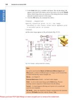
2. Construct each of the drawings which will form the sheet set in this
drawing template. The whole set of drawings is shown in Fig. 11.2.
Save the drawings in a directory – in this example this has been given
the name 62 Pheasant Drive.
3. Click Sheet Set Manager in the View/Palettes panel (Fig. 11.3). The
Sheet Set Manager palette appears (Fig. 11.4). Click New Sheet
Set… in the popup menu at the top of the palettes. The first of a series
of Create Sheet Set dialogs appears – the Create Sheet Set – Begin
Sheet sets
chapter 11
211
Sheet Set
Sub set
Fig. 11.2 The eight drawings in the 62 Pheasant Drive sheet set
Fig. 11.3 Selecting Sheet Set Manager from the View/Palettes panel
Fig. 11.4 The Sheet Set Manager palette
Introduction to AutoCAD 2011
chapter 11
212
dialog (Fig. 11.5). Click the radio button next to Existing drawings,
followed by a click on the Next button and the next dialog Sheet Set
Details appears (Fig. 11.6).
4. Enter details as shown in the dialog as shown in Fig. 11.6. Then click the
Next button to bring the Choose Layouts dialog to screen (Fig. 11.7).
Fig. 11.5 The first of the Create Sheet Set dialogs – Begin
Fig. 11.6 The Sheet Set Details dialog
Sheet sets
chapter 11
213
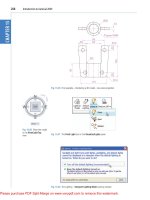
5. Click its Browse button and from the Browse for Folder list which
comes to screen, pick the directory 62 Pheasant Drive. Click the OK
button and the drawings held in the directory appears in the Choose
Layouts dialog (Fig. 11.7). If satisfied the list is correct, click the Next
button. A Confirm dialog appears (Fig. 11.8). If satisfied click the
Finish button and the Sheet Set Manager palette appears showing the
drawings which will be in the 62 Pheasant Drive sheet set (Fig. 11.9).
Fig. 11.7 The Choose Layouts dialog
Fig. 11.8 The Confirm dialog
Introduction to AutoCAD 2011
chapter 11
214
62 Pheasant Drive DWF
1. In the 62 Pheasant Drive Sheet Set Manager click the Publish icon,
followed by a click on Publish to DWF in the menu which appears
(Fig. 11.10). The Specify DWF File dialog appears (Fig. 11.11).
Enter 62 Pheasant Drive in the File name field followed by a click
Fig. 11.9 The Sheet Manager palette for 62 Pheasant Drive
Notes
1. The eight drawings in the sheet set are shown in Fig. 11.9. If any of
the drawings in the sheet set are subsequently amended or changed,
when the drawings is opened again from the 62 Pheasant Drive
Sheet Manager palette, the drawing will include any changes or
amendments.
2. Drawings can only be placed into sheet sets if they have been saved
in a Layout screen. Note that all the drawings shown in the 62
Pheasant Drive Sheet Set Manager have Layout1 after the drawing
names because each has been saved after being constructed in a
Layout1 template.
3. Sheet sets in the form of DWF (Design Web Format) files can be
sent via email to others who are using the drawings or placed on
an intranet. The method of producing a DWF for the 62 Pheasant
Drive Sheet Set follows.
Sheet sets
chapter 11
215
on the Select button. A warning window (Fig. 11.12) appears. Click its
Close button. The Publish Job in Progress icon in the bottom right-
hand corner of the AutoCAD 2011 window starts fluctuating in shape
showing that the DWF file is being processed (Fig. 11.12). When the
icon becomes stationary right-click the icon and click View Plotted
File… in the right-click menu which appears (Fig. 11.13).
Fig. 11.10 The Publish icon in the Sheet Set Manager
Fig. 11.11 The Select DWF File dialog
Introduction to AutoCAD 2011
chapter 11
216
2. The Autodesk Design Review window appears showing the
62 Pheasant Drive.dwf file (Fig. 11.14). Click on the arrow Next Page
(Page on) to see other drawings in the DWF file.
Fig. 11.12 The Publish Job in Progress icon
Fig. 11.13 The right-click menu of the icon
Fig. 11.14 The Autodesk Design Review showing details of the 62 Pheasant Drive.dwf file
Sheet sets
chapter 11
217
3. If required the Design Review file can be sent between people by email
as an attachment, opened in a company’s intranet or, indeed, included
within an internet web page.
REVISION NOTES
1. To start off a new sheet set, select the Sheet Set Manager icon in the Tools/Palettes panel.
2. Sheet sets can only contain drawings saved in Layout format.
3. Sheet sets can be published as Design Review Format (*.dwf) files which can be sent
between offices by email, published on an intranet or published on a web page.
4. Subsets can be included in sheet sets.
5. Changes or amendments made to any drawings in a sheet set are reflected in the sheet
set drawings when the sheet set is opened.
Introduction to AutoCAD 2010
chapter 1
218
Introduction to AutoCAD 2011
chapter 11
218
Fig. 11.16 The DWF for exercise 1
Holes Ø10
Hole Ø20
20
15
25
25
20
20
8
semi-sphere Ø64
semi-sphere Ø40
Pin 70xØ20
45
150
Ø58
Ø70
R20
R20
70
DO NOT SCALE
63
45
30
M10
58
A. READER Scale 1:1 Date: 23:6:2007
PISTON & CONNECTING ROD
Part: 8/45+8/46
Dimensions in millimetres
Fig. 11.15 Exercise 1 – exploded orthographic projection
Exercises
Methods of constructing answers to the following exercises can be found in the free website:
/>1. Fig. 11.15 is an exploded orthographic
projection of the parts of a piston and its
connecting rod. There are four parts in the
assembly. Small drawings of the required
sheet set are shown in Fig. 11.17.
Construct the drawing Fig. 11.15 and also
the four drawings of its parts. Save each of the
drawings in a Layout1 format and construct
the sheet set which contains the ve drawings
(Fig. 11.17).
Introducing AutoCAD 2010
chapter 1
219
Sheet sets
chapter 11
219
23
150
Sphere Ø64
8
20
Hole Ø20
25
Sphere Ø40
A. Reader
Scale 1:1
Date 23:06:2007 Part: 8/45
DO NOT SCALE
A. Reader
Scale 1:1
Date 23:06:2007
DO NOT SCALEDimensions in millimetres
Holes Ø10
20
35
63
58
Ø70
A. Reader
Scale 1:1
Date 23:06:2007 Part: 8/46
DO NOT SCALEDimensions in millimetres
M10
30
45
Pin 70xØ20
Cham 2x2
A. Reader
Scale 1:1
BOLT & PINDate 23:06:2007 Parts: 8/46 & 8/47
DO NOT SCALEDimensions in millimetres
Part: 8/48
Holes Ø10
63
58
70150
2020
Ø70
Sphere Ø40
Sphere Ø64
8
20
M10
30
45
Hole Ø20
25
R20
Pin 70xØ20
A. READER Scale 1:1 Date: 23:6:2007 PISTON & CONNECTING RODPart: 8/45+8/46
Dimensions in millimetres DO NOT SCALE
23
R16
R8
R10
Hole Ø20
35
Sphere Ø64
R10
Fig. 11.17 Exercise 1 – the five drawings in the sheet set
1
2
3
4
5
6
SPINDLE AND PIN
SHOULDER WASHERS
BRACKET
LOCKSCREW
WASHER
HANDLE
Part No. Name of part
1
AA
3
5
6
4
2
MACHINE ADJUSTING SPINDLE
5.10�
1.00�
Tapped M12
1.00�
0.03
3.40�
0.25�
0.70�
2.35�
0.60�
0.40�
0.20�
R0.25�
R0.50�
R1.80�
0.50�
0.35�
3.15�
0.65�
1.60�
1.40�
40°
Hole Ø10
Ø0.95�
0.50�
Ø0.25�
Ø1.00�
Ø0.1�
Ø1.20�
Fig. 11.18 Exercise 2
Construct the DWF le of the sheet set.
Experiment sending it to a friend via email as
an attachment to a document, asking him/
her to return the whole email to you without
changes. When the email is returned, open its
DWF le and click each drawing icon in turn to
check the contents of the drawings.
2. Construct a similar sheet set as in the answer
to Exercise 1 from the exploded orthographic
drawing of a Machine adjusting spindle
given in Fig. 11.18.
223
AIMS OF THIS CHAPTER
The aims of this chapter are:
1. To introduce the tools used for the construction of 3D solid models.
2. To give examples of the construction of 3D solid models using tools from the
Home/Create panel.
3. To give examples of 2D outlines suitable as a basis for the construction of 3D solid
models.
4. To give examples of constructions involving the Boolean operators – Union, Subtract
and Intersect.
Chapter 12
Introducing 3D
modeling
Introduction to AutoCAD 2011
chapter 12
224
Introduction
As shown in Chapter 1 the AutoCAD coordinate system includes a third
coordinate direction Z, which, when dealing with 2D drawing in previous
chapters, has not been used. 3D model drawings make use of this third Z
coordinate.
The 3D Basics workspace
It is possible to construct 3D model drawings in the 2D Drafting &
Annotation workspaces, but in Part 2 of this book we will be working in
either the 3D Basics or in the 3D Modeling workspaces. To set the first of
these workspaces click the Workspace Settings icon in the status bar and
select 3D Introduction from the menu which appears (Fig. 12.1). The 3D
Basics workspace appears (Fig. 12.2).
Fig. 12.1 Selecting 3D Basics from the Workspace Switching menu
The workspace in Fig. 12.2 is the window in which the examples in this
chapter will be constructed.
Methods of calling tools for 3D modeling
The default panels of the 3D Basics ribbon are shown in Fig. 12.3.
When calling the tools for the construction of 3D model drawings, 3D
tools can be called by:
1. A click on a tool icon in a 3D Basics panel.
2. Entering the tool name at the command line followed by pressing the
Return button of the mouse or the Return key of the keyboard.
Introducing 3D modeling
chapter 12
225
3. Some of the 3D tools have an abbreviation which can be entered at the
command line instead of its full name.
4. Using the Dynamic Input method.
Fig. 12.2 The 3D Basics workspace
Fig. 12.3 The default 3D Basics panels
Notes
1. As when constructing 2D drawings, no matter which method is used
and most operators will use a variety of these four methods, the
result of calling a tool results in prompt sequences appearing at the
Introduction to AutoCAD 2011
chapter 12
226
command prompt (or if using Dynamic Input on screen) as in the
following example:
Command: enter box right-click
Specify first corner or [Center]: enter 90,120
right-click
Specify other corner or [Cube/Length]: enter
150,200
Specify height or [2Point]: enter 50
Command:
Or, if the tool is called from its tool icon, or from a drop-down menu:
Command:_box
Specify first corner or [Center]: enter 90,120
right-click
Specify other corner or [Cube/Length]: enter
150,200
Specify height or [2Point]: enter 50
Command:
2. In the following pages, if the tool’s sequences are to be repeated,
they may be replaced by an abbreviated form such as:
Command: box
[prompts]: 90,120
[prompts]: 150,200
3. The examples shown in this chapter will be based on layers set as
follows:
a. Click the Layer Properties icon in the Home/Layers & View
panel (Fig. 12.4).
Fig. 12.4 The Layer Properties icon in the Layers & View panel
Introducing 3D modeling
chapter 12
227
The Polysolid tool (Fig. 12.8)
1. Set layer Blue as the current layer.
2. Construct an octagon of edge length 60 using the Polygon tool.
3. Click SW Isometric in the Layers & View panel (Fig. 12.6).
4. Call the Polysolid tool from the Home/Create panel (Fig. 12.7).
The command line shows:
Command: _Polysolid Height=0, Width=0,
Justification=Center
Specify start point or [Object/Height/Width/
Justify] <Object>: enter h right-click
Specify height <0>: enter 60 right-click
Height=60, Width=0, Justification=Center
Specify start point or [Object/Height/Width/
Justify] <Object>: enter w right-click
Specify width <0>: 5
Height=60, Width=5, Justification=Center
b. In the Layer Properties Manager which appears make settings
as shown in Fig. 12.5.
Fig. 12.5 The settings in the Layer Properties Manager
Introduction to AutoCAD 2011
chapter 12
228
Fig. 12.7 The Polysolid tool icon in the Home/Create panel
Fig. 12.6 Selecting SW Isometric from 3D Navigation drop-down menu in the Layers & View panel
Introducing 3D modeling
chapter 12
229
Specify start point or [Object/Height/Width/
Justify] <Object>: pick the polygon
Select object: right-click
Command:
And the Polysolid forms.
5. Select Conceptual from the Layers & View panel (Fig. 12.8).
The result is shown in Fig. 12.9.
Fig. 12.9 The Polysolid
tool example
Fig. 12.8 Selecting Conceptual shading from Visual Styles in the Layers & View panel
2D outlines suitable for 3D models
When constructing 2D outlines suitable as a basis for constructing some
forms of 3D model, select a tool from the Home/Draw panel, or enter tool
names or abbreviations for the tools at the command line. If constructed
using tools such as Line, Circle and Ellipse, before being of any use for
3D modeling, outlines must be changed into regions with the Region tool.
Closed polylines can be used without the need to use the Region tool.
Introduction to AutoCAD 2011
chapter 12
230
Example – Outlines & Region (Fig. 12.10)
1. Construct the left-hand drawing of Fig. 12.10 using the Line and
Circle tools.
3. Union of 2 unions1. 3 regions
4. Subtract region from Union2. Union of 3 regions
30
60
60
70
R25
Fig. 12.10 Example – Line and circle outlines and Region
2. Enter region or reg at the command line. The command line shows:
Command:_region
Select objects: window the left-hand rectangle
1 found
Select objects: right-click
1 loop extracted.
1 Region created.
Command:
And the Line outline is changed to a region. Repeat for the circle and the
right-hand rectangle. Three regions will be formed.
3. Drawing 2 – call the Union tool from the Home/Edit panel (Fig. 12.11).
The command line shows:
Command: _union
Select objects: pick the left-hand region 1 found
Select objects: pick the circular region 1 found,
2 total
Select objects: pick the right-hand region 1 found,
3 total
Select objects: right-click
Command:
Introducing 3D modeling
chapter 12
231
4. Drawing 3 – with the Union tool form a union of the left-hand region
and the circular region.
5. Drawing 4 – call the Subtract tool, also from the Home/Edit panel.
The command line shows:
Command:_subtract Select solids and regions to
subtract from
Select objects: pick the region just formed 1 found
Select objects: right-click
Select solids and regions to subtract
Select objects: pick the right-hand region 1 found
Select objects: right-click
Command:
The Extrude tool
The Extrude tool can be called with a click on its name in the Home/
Create panel (Fig. 12.12), or by entering extrude or its abbreviation ext at
the command line.
Fig. 12.11 Selecting the Union tool from the Home/Edit panel
Fig. 12.12 The Extrude tool from the Home/Create panel
Introduction to AutoCAD 2011
chapter 12
232
Examples of the use of the Extrude tool
The first two examples of forming regions given in Figs 12.10 and 12.11
are used to show the results of using the Extrude tool.
First example – Extrude (Fig. 12.13)
From the first example of forming a region:
1. Open Fig. 12.10. Erase all but the region 2.
2. Make layer Green current.
3. Call Extrude (Fig. 12.12). The command line shows:
Command: _extrude
Current wire frame density: ISOLINES=4
Closed profiles creation mode=Solid
Select objects to extrude or [MOde]: pick region
1 found
Select objects to extrude or [MOde]: right click
Specify height of extrusion or [Direction/Path/
Taper angle/Expression] <45>: enter 50 right-
click
Command:
4. Place in the Layers & View/3D Navigation/SW/Isometric view.
5. Call Zoom and zoom to 1.
6. Place in Visual Style/Realistic.
The result is shown in Fig. 12.13.
Fig. 12.13 First example – Extrude
Introducing 3D modeling
chapter 12
233
Second example – Extrude (Fig. 12.14)
1. Open Fig. 12.10 and erase all but the region 3.
2. Make the layer Blue current.
3. Set ISOLINES to 16.
4. Call the Extrude tool. The command line shows:
Command: _extrude
Current wire frame density: ISOLINES=4, Closed
profiles creation mode=Solid
Select objects to extrude or [MOde]: _MO Closed
profiles creation mode
[SOlid/SUrface] <Solid>: _SO
Select objects to extrude or [MOde]: pick the
region 3 1 found
Select objects to extrude or [MOde]:
Notes
1. In the above example we made use of an isometric view possible
from the 3D Navigation drop-down menu in the Home/Layers &
Views panel (Fig. 12.6). The 3D Navigation drop-down menu
allows a model to be shown in a variety of views.
2. Note the Current wire frame density: ISOLINES4 in the
prompts sequence when Extrude is called. The setting of 4 is
suitable when extruding plines or regions consisting of straight lines,
but when arcs are being extruded it may be better to set ISOLINES
to a higher figure as follows:
Command: enter isolines right-click
Enter new value for ISOLINES <4>: enter 16
right-click
Command:
3. Note the prompt [MOde] in the line
Select objects to extrude or [MOde]:
If mo is entered as a response to this prompt line, the following prompts
appear:
Closed profiles creation mode[SOlid/SUrface]
<Solid>: _SO
which allows the extrusion to be in solid or surface format.
Introduction to AutoCAD 2011
chapter 12
234
Specify height of extrusion or [Direction/Path/
Taper angle/Expression]: enter t right-click
Specify angle of taper for extrusion or
[Expression] <0>: enter 10 right-click
Specify height of extrusion or [Direction/Path/
Taper angle/Expression]: enter 100 right-click
Command:
3. In the Layers & View/3D Navigation menu select NE Isometric.
4. Zoom to 1.
5. Place in Visual Styles/Hidden.
The result is shown in Fig. 12.14.
Third example – Extrude (Fig. 12.16)
1. Make layer Magnolia current.
2. Construct an 80 50 rectangle, filleted to a radius of 15. Then in
the 3D Navigation/Front view and using the 3D Polyline tool from
the Home/Draw panel (Fig. 12.15), construct 3 3D polylines each of
length 45 and at 45 degree to each other at the centre of the outline as
shown in Fig. 12.16.
3. Place the screen in the 3D Navigation/SW Isometric view.
4. Set ISOLINES to 24.
5. Call the Extrude tool. The command line shows:
Command: _extrude
Current wire frame density: ISOLINES = 24, Closed
profiles creation mode = Solid
Select objects to extrude or [MOde]: _MO Closed
profiles creation mode
[SOlid/SUrface] <Solid>: _SO
Select objects to extrude or [MOde]: pick the
rectangle 1 found
Select objects to extrude or [MOde]: right-click
Specify height of extrusion or [Direction/Path/
Taper angle/Expression]:enter t right-click
Select extrusion path or [Taper angle]: pick path
right-click
Command:
6. Place the model in Visual Styles/Realistic.
The result is shown in Fig. 12.16.
Fig. 12.15 The 3D
Polyline tool from the
Home/Draw panel
Fig. 12.14 Second
example – Extrude
Introducing 3D modeling
chapter 12
235
The Revolve tool
The Revolve tool can be called with a click on its tool icon in the Home/
Create panel, by a click or by entering revolve at the command line, or its
abbreviation rev.
Examples of the use of the Revolve tool
Solids of revolution can be constructed from closed plines or from regions.
First example – Revolve (Fig. 12.19)
1. Construct the closed polyline (Fig. 12.17).
2. Make layer Red current.
3. Set ISOLINES to 24.
4. Call the Revolve tool from the Home/Create panel (Fig. 12.18).
The command line shows:
Command: _revolve
Current wire frame density: ISOLINES=4, Closed
profiles creation mode=Solid
Select objects to revolve or [MOde]: _MO Closed
profiles creation mode[SOlid/SUrface] <Solid>: _SO
45
45
10
15
8510
280
R5
R10
Start point for axis
Axis endpoint
Fig. 12.17 First example – Revolve. The closed pline
Path
Object
Fig. 12.16 Second example – Extrude
Introduction to AutoCAD 2011
chapter 12
236
Semi-ellipse based
on 180 x 100 axes
4
40
4
Fig. 12.20 Second example – Revolve. The pline outline
Fig. 12.18 The Revolve tool from the Home/Create panel
Select objects to revolve or [MOde]: pick the
pline 1 found
Select objects to revolve or [MOde]: right-click
Specify axis start point or define axis by [Object/
X/Y/Z] <Object>: pick
Specify axis endpoint: pick
Specify angle of revolution or [STart angle/
Reverse/Expression] <360>: right-click
Command:
5. Place in the 3D Navigation/NE Isometric view. Zoom to 1.
6. Shade with Visual Styles/Shaded.
The result is shown in Fig. 12.19.
Second example – Revolve (Fig. 12.21)
1. Make layer Yellow current.
2. Place the screen in the 3D Navigate/Front view. Zoom to 1.
3. Construct the pline outline (Fig. 12.20).
Fig. 12.19 First
example – Revolve