Introduction to AutoCAD 2011- P13 potx
Bạn đang xem bản rút gọn của tài liệu. Xem và tải ngay bản đầy đủ của tài liệu tại đây (2.43 MB, 30 trang )
Introduction to AutoCAD 2010
chapter 1
364
Introduction to AutoCAD 2011
364
chapter 17
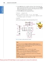
7. An orthographic projection of the parts of a lathe steady is given in Fig. 17.43. From the dimensions
shown in the drawing, construct an assembled 3D model of the lathe steady.
When the 3D model has been completed, add suitable lighting and materials and render the
model (Fig. 17.44).
Ø30Hole Ø20
R20
Ø20
15 40
100
140
45
R3
R35
Fig. 17.42 Exercise 6
A
A
98
13
10
63
30
45
30
40
13
80°
R24
90°
Ø20
HOLES Ø10
BOSS Ø16
TAPPED M8
80
5
45
10
Ø16
12
M10 Ø20
30�Ø10
26
3
M10 Ø20
40
10
10
123
16
M8
1
2
3
4
5
6
Name:
Scale:
Date:
Title:
A. Student
1:1
15/03/2008
LATHE STEADY
Dimensions in millimetres
DO NOT SCALE THIS DRAWING
Fig. 17.43 Exercise 7 – details
Introducing AutoCAD 2010
chapter 1
365
Three-dimensional space
365
chapter 17
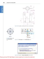
8. Construct suitable polylines to sizes of your own discretion in order to form the two surfaces to form
the box shape shown in Fig. 17.45 with the aid of the Rulesurf tool. Add lighting and a material and
render the surfaces so formed. Construct another three
Edgesurf surfaces to form a lid for the box.
Place the surface in a position above the box, add a material and render (Fig. 17.46).
Fig. 17.44 Exercise 7 – a rendering
Fig. 17.45 Exercise 8 – the box
Fig. 17.46 Exercise 8 – the box and its lid
80808080
20 20
Fig. 17.47 Exercise 9 – one of the polylines from which the surface was obtained
9. Fig. 17.47 shows a polyline for each of the 4 objects from which the surface shown in Fig. 17.48 was
obtained. Construct the surface and shade in Shades of Gray.
Introduction to AutoCAD 2010
chapter 1
366
Introduction to AutoCAD 2011
366
chapter 17
10. The surface model for this exercise was constructed from three Edgesurf surfaces working to the
suggested objects for the surface as shown in Fig. 17.49. The sizes of the outlines of the objects in each
case are left to your discretion. Fig. 17.50 shows the completed surface model. Fig. 17.51 shows the
three surfaces of the model separated from each other.
Fig. 17.48 Exercise 9
Fig. 17.50 Exercise 10
Fig. 17.49 Outlines for the three surfaces
Object 1
Object 2
Object 3
Object 4
Object 4
Object 3
Object 2
Object 1
Object 1
from its
front
Object 3
from its
front
Fig. 17.51 The three surfaces
Introducing AutoCAD 2010
chapter 1
367
Three-dimensional space
367
chapter 17
11. Fig. 17.52 shows in a View Block/Isometric view a semicircle of radius 25 constructed in the View
Cube/Top view on a layer of colour Magenta with a semicircle of radius 75 constructed on the
View Block/Front view with its left-hand end centred on the semicircle. Fig. 17.53 shows a surface
constructed from the two semicircles in a Visual Styles/Realistic mode.
Fig. 17.53 Exercise 11
Fig. 17.52 Exercise 11 – the circle and semicircle
369
AIMS OF THIS CHAPTER
The aims of this chapter are:
1. To introduce the use of tools from the Solid Editing panel.
2. To show examples of a variety of 3D solid models.
Chapter 18
Editing 3D solid
models
Introduction to AutoCAD 2011
chapter 18
370
The Solid Editing tools
The Solid Editing tools can be selected from the Home/Solid Editing
panel (Fig. 18.1).
Fig. 18.1 The Home/Solid Editing panel
Original
cylinder
After extruding
faces along paths
Fig. 18.3 First
example – Extrude
faces tool
R40
40
40
45
70
R40
Fig. 18.2 First example – Extrude faces tool – first stages
Examples of the results of using some of the Solid Editing tools are shown
in this chapter. These tools are of value if the design of a 3D solid model
requires to be changed (edited), although some have a value in constructing
parts of 3D solids which cannot easily be constructed using other tools.
First example – Extrude faces tool (Fig. 18.3)
1. Set ISOLINES to 24.
2. In a ViewCube/Right view, construct a cylinder of radius 30 and
height 30 (Fig. 18.3).
3. In a ViewCube/Front view, construct the pline (Fig. 18.2). Mirror the
pline to the other end of the cylinder.
Editing 3D solid models
chapter 18
371
4. In a ViewCube/Top view, move the pline to lie central to the cylinder.
5. Place the screen in a ViewCube/Isometric view.
6. Click the Extrude faces tool icon in the Home/Solid Editing panel
(Fig. 18.1). The command line shows:
Command: _solidedit
Solids editing automatic checking: SOLIDCHECK=1
Enter a solids editing option [Face/Edge/Body/
Undo/eXit] <eXit>: _face
Enter a face editing option
[Extrude/Move/Rotate/Offset/Taper/Delete/Copy/
coLor/mAterial/Undo/eXit] <eXit>: _extrude
Select faces or [Undo/Remove]: pick the cylinder 2
faces found.
Select faces or [Undo/Remove/ALL]: enter r right-
click
Remove faces or [Undo/Add/ALL]: right-click
Specify height of extrusion or [Path]: enter
p (Path)right-click
Select extrusion path: pick the left-hand path
pline
Solid validation started.
Solid validation completed.
Enter a face editing option [Extrude/Move/Rotate/
Offset/Taper/Delete/Copy/coLor/mAterial/Undo/
eXit] <eXit>: right-click
Command:
7. Repeat the operation using the pline at the other end of the cylinder as a
path.
8. Add lights and a material and render the 3D model (Fig. 18.3).
Note
Note the prompt line which includes the statement SOLIDCHECK=1.
If the variable SOLIDCHECK is set on (to 1) the prompt lines include
the lines SOLIDCHECK=1, Solid validation started and Solid
validation completed. If set to 0 these two lines do not show.
Second example – Extrude faces tool (Fig. 18.5)
1. Construct a hexagonal extrusion just 1 unit high in the ViewCube/Top.
2. Change to the ViewCube/Front and construct the curved pline (Fig. 18.4).
Extruded hexagon
of height 1 unit
Path -
a pline
Fig. 18.4 Second
example – Extrude
faces tool – pline for
path
Introduction to AutoCAD 2011
chapter 18
372
Third example – Move faces tool (Fig. 18.6)
1. Construct the 3D solid drawing shown in the left-hand drawing of
Fig. 18.6 from three boxes which have been united using the Union tool.
2. Click on the Move faces tool in the Home/Solid Editing panel (see
Fig. 18.1). The command line shows:
Command: _solidedit
[prompts] _face
Enter a face editing option
[prompts]: _move
Select faces or [Undo/Remove]: pick the model face
4 face found.
Select faces or [Undo/Remove/ALL]: right-click
Specify a base point or displacement: pick
Specify a second point of displacement: pick
[further prompts]:
And the picked face is moved – right-hand drawing of Fig. 18.6.
3. Back in the Top view, move the pline to lie central to the extrusion.
4. Place in the ViewCube/Isometric view and extrude the top face of the
extrusion along the path of the curved pline.
5. Add lighting and a material to the model and render (Fig. 18.5).
Fig. 18.5 Second
example – Extrude
faces tool
After
Move Faces
Before
Move Faces
Fig. 18.6 Third example – Solid, Move faces tool
Note
This example shows that a face of a 3D solid model can be extruded
along any suitable path curve. If the polygon on which the extrusion had
been based had been turned into a region, no extrusion could have taken
place. The polygon had to be extruded to give a face to a 3D solid.
Editing 3D solid models
chapter 18
373
Fourth example – Oset faces (Fig. 18.7)
1. Construct the 3D solid drawing shown in the left-hand drawing of
Fig. 18.7 from a hexagonal extrusion and a cylinder which have been
united using the Union tool.
Original model
Bottom Face
Offset
Upper Face
Offset
Side Face
Offset
Fig. 18.7 Fourth example – Offset faces tool
2. Click on the Offset faces tool icon in the Home/Solid Editing panel
(Fig. 18.1). The command line shows:
Command:_solidedit
[prompts]:_face
[prompts]
[prompts]:_offset
Select faces or [Undo/Remove]: pick the bottom
face of the 3D model 2 faces found.
Select faces or [Undo/Remove/All]: enter r right-
click
Select faces or [Undo/Remove/All]: pick
highlighted faces other than the bottom face 2
faces found, 1 removed
Select faces or [Undo/Remove/All]: right-click
Specify the offset distance: enter 30 right-click
3. Repeat, offsetting the upper face of the cylinder by 50 and the right-
hand face of the lower extrusion by 15.
The results are shown in Fig. 18.9.
Introduction to AutoCAD 2011
chapter 18
374
Fifth example – Taper faces tool (Fig. 18.8)
1. Construct the 3D model as in the left-hand drawing of Fig. 18.8. Place
in ViewCube/Isometric view.
Before Taper Faces After Taper Faces
Fig. 18.8 Fifth example – Taper faces tool
2. Call Taper faces. The command line shows:
Command:_solidedit
[prompts]:_face
[prompts]
[prompts]:_taper
Select faces or [Undo/Remove]: pick the upper face
of the base 2 faces found.
Select faces or [Undo/Remove/All]: enter r right-
click
Select faces or [Undo/Remove/All]: pick
highlighted faces other than the upper face 2
faces found, 1 removed
Select faces or [Undo/Remove/All]: right-click
Specify the base point: pick a point on left-hand
edge of the face
Specify another point along the axis of tapering:
pick a point on the right-hand edge of
the face
Specify the taper angle: enter 10 right-click
And the selected face tapers as indicated in the right-hand drawing of
Fig. 18.8.
Editing 3D solid models
chapter 18
375
Sixth example – Copy faces tool (Fig. 18.10)
1. Construct a 3D model to the sizes as given in Fig. 18.9.
250
5
20
Ø60
R50
Ø50
R20
R15
R20180
90
All offsets are 5
130
Fig. 18.9 Sixth example – Copy Faces tool – details of the 3D solid model
2. Click on the Copy faces tool in the Home/Solid Editing panel
(Fig. 18.1). The command line shows:
Command:_solidedit
[prompts]:_face
[prompts]
[prompts]:_copy
Select faces or [Undo/Remove]: pick the upper face
of the solid model 2 faces found.
Select faces or [Undo/Remove/All]: enter r right-
click
Select faces or [Undo/Remove/All]: pick highlighted
face not to be copied 2 faces found, 1 removed
Select faces or [Undo/Remove/All]: right-click
Specify a base point or displacement: pick
anywhere on the highlighted face
Specify a second point of displacement: pick
a point some 50 units above the face
3. Add lights and a material to the 3D model and its copied face and
render (Fig. 18.10).
Introduction to AutoCAD 2011
chapter 18
376
Seventh example – Color faces tool (Fig. 18.12)
1. Construct a 3D model of the wheel to the sizes as shown in
Fig. 18.11.
Ø40
Ø200
Ø210
Ø220
R70
R90
R35
10
R5
5
50
Fig. 18.11 Seventh example – Color faces tool – details of the 3D model
Before Copy Faces After Copy Faces
Fig. 18.10 Sixth example – Copy faces tool
2. Click the Color faces tool icon in the Home/Solid Editing panel
(Fig. 18.1). The command line shows:
Command:_solidedit
[prompts]:_face
Editing 3D solid models
chapter 18
377
[prompts]
[prompts]:_color
Select faces or [Undo/Remove]: pick the inner face
of the wheel 2 faces found
Select faces or [Undo/Remove/All]: enter r right-
click
Select faces or [Undo/Remove/All]: pick
highlighted faces other than the required face 2
faces found, 1 removed
Enter new color <ByLayer>: enter 1 (which is red)
right-click
3. Add lights and a material to the edited 3D model and render
(Fig. 18.12).
Fig. 18.12 Seventh example – Color faces tool
Examples of more 3D models
The following 3D models can be constructed in the 3d acadiso.dwt screen.
The descriptions of the stages needed to construct them have been reduced
from those given in earlier pages, in the hope that readers have already
acquired a reasonable skill in the construction of such drawings.
First example (Fig. 18.14)
1. Front view. Construct the three extrusions for the back panel and the
two extruding panels to the details given in Fig. 18.13.
Introduction to AutoCAD 2011
chapter 18
378
2. Top view. Move the two panels to the front of the body and union
the three extrusions. Construct the extrusions for the projecting parts
holding the pin.
3. Front view. Move the two extrusions into position and union them to
the back.
4. Top view. Construct two cylinders for the pin and its head.
5. Top view. Move the head to the pin and union the two cylinders.
6. Front view. Move the pin into its position in the holder. Add lights and
materials.
7. Isometric view. Render. Adjust lighting and materials as necessary
(Fig. 18.14).
Second example (Fig. 18.16)
1. Top. (Fig. 18.15) Construct polyline outlines for the body extrusion
and the solids of revolution for the two end parts. Extrude the body and
subtract its hole and using the Revolve tool form the two end solids of
revolution.
2. Right. Move the two solids of revolution into their correct positions
relative to the body and union the three parts. Construct a cylinder for
the hole through the model.
3. Front. Move the cylinder to its correct position and subtract from the
model.
4. Top. Add lighting and a material.
5. Isometric. Render (Fig. 18.16).
Fillets are R5
100
5
20
R25
Hole Ø40
R20
R15
110
70
180
7.5
10
40
Holes Ø20
Ø50
Ø40
20
200
Pin
Fig. 18.13 First example – 3D models – details of sizes and shapes
Fig. 18.14 First
example – 3D models
Editing 3D solid models
chapter 18
379
Third example (Fig. 18.18)
1. Front. Construct the three plines needed for the extrusions of each part
of the model (details Fig. 18.17). Extrude to the given heights. Subtract
the hole from the 20 high extrusion.
Fig. 18.16 Second example – 3D models
Hole Ø20
Ø40
10
5
25
252520
10
160 60
60
Ø40
Ø30
Hole Ø60
R40
Fig. 18.15 Second example – 3D models dimensions
907060
10
25
Hole Ø20
20
80
R10
60
R60
R40
40
10
Fig. 18.17 Third example – 3D models – details of shapes and sizes
Introduction to AutoCAD 2011
chapter 18
380
2. Top. Move the 60 extrusion and the 10 extrusion into their correct
positions relative to the 20 extrusion. With Union form a single 3D
model from the three extrusions.
3. Add suitable lighting and a material to the model.
4. Isometric. Render (Fig. 18.18).
50
160
R500
5
15
A
xis
5
1
Detail at A
A
Fig. 18.19 Fourth example – 3D models
Fig. 18.18 Third example – 3D models
Fourth example (Fig. 18.19)
1. Front. Construct the polyline – left-hand drawing of Fig. 18.19.
2. With the Revolve tool from the Home/3D Modeling panel construct a
solid of revolution from the pline.
3. Top. Add suitable lighting a coloured glass material.
4. Isometric. Render – right-hand illustration of Fig. 18.19.
Introducing AutoCAD 2010
chapter 1
381
Editing 3D solid models
chapter 18
381
Exercises
Methods of constructing answers to the following exercises can be found in the free website:
/>0.90"
Ø0.70"
Ø1.65
Ø1.05"
3.50"
5.25"
0.55"
0.30"
0.40"
1.25"
2.20"
0.60"
Ø1.05"
Ø0.80"
M0.70"
R6.10"
0.10"
Fig. 18.20 Exercise 1 – orthographic projection
Fig. 18.21 Exercise 1 – rendered 3D model
2. Working to the dimensions given in the
orthographic projections of the three parts
of this 3D model (Fig. 18.22), construct the
assembled as shown in the rendered 3D
model (Fig. 18.23). Add suitable lighting
and materials, place in one of the isometric
viewing position and render the model.
1. Working to the shapes and dimensions as
given in the orthographic projection of Fig.
18.20, construct the exploded 3D model as
shown in Fig. 18.21. When the model has
been constructed add suitable lighting and
apply materials, followed by rendering.
230
148
75
70
10
80
160
80
Ø40
10
80
15
Hole Ø50
Ø60
Ø125
Ø80
Ø50
35
12.5
245
Holes Ø10
Hole Ø10
Ø20
Ø30
Holes Ø10
R10
R5
Fig. 18.22 Exercise 2 – details of shapes and sizes
Fig. 18.23 Exercise 2
Introduction to AutoCAD 2010
chapter 1
382
Introduction to AutoCAD 2011
chapter 18
382
3. Construct the 3D model shown in the rendering (Fig. 18.24) from the details given in the parts drawing
(Fig. 18.25).
Fig. 18.24 Exercise 3
1550
200
200
20
10
30
Holes Ø10
R10
155
Ø120
5
10
10
60
10
Ø20
M15
135
R5
Ø110
R300
Holes Ø15
R15
Tapped M15
BASE
UPRIGHT
ARM
BOLTS
140
R15
R105
R95
Fig. 18.25 Exercise 3 – the parts drawing
4. A more dicult exercise.
A rendered 3D model of the parts of an assembly is
shown in Fig. 18.26.
15
275
Holes Ø10
15
R115
R20
Hole Ø50
112.5
20
5
Ø70
Ø110
SQ 150
R105
40
12.5
5
5
Fig. 18.26 Exercise 4 – first orthographic projection
Introducing AutoCAD 2010
chapter 1
383
Editing 3D solid models
chapter 18
383
Working to the details given in the three orthographic projections (Figs 18.26–18.28), construct the two
parts of the 3D model, place them in suitable positions relative to each other, add lighting and materials and
render the model (Fig. 18.29).
Fillets are R2
85 65
10
Hole Ø10
Ø15
15
10
Fig. 18.27 Exercise 4 – third orthographic projections
92.5
152.5
R40
27.5
50
50
10
55
15
200
15
Ø50
Holes Ø30
Hole Ø40
R60
R5
Fig. 18.28 Exercise 4 – second orthographic projection
Fig. 18.29 Exercise 4
385
AIMS OF THIS CHAPTER
The aims of this chapter are:
1. To give a further example of placing raster images in an AutoCAD drawing.
2. To give examples of methods of printing or plotting not given in previous chapters.
3. To give examples of polygonal viewports.
Chapter 19
Other features of 3D
modeling
Introduction to AutoCAD 2011
chapter 19
386
Raster images in AutoCAD drawings
Example – Raster image in a drawing (Fig. 19.5)
This example shows the raster file Fig05.bmp of the 3D model constructed
to the details given in Fig. 19.1.
5
28
180
90
4040
50
Ø30
Hole Ø50
Holes Ø20
Holes Ø6
Ø20
Ø60
Ø30
5
40
10
Ø5
Ø10
Fig. 19.1 Raster image in a drawing – drawings into which file is to be inserted
Fig. 19.2 Selecting External Reference Palette from the View/Palettes panel
Fig. 19.3 The External
References palette
Raster images are graphics images in files with file names ending with
the extensions *.bmp, *.pcx, *.tif and the like. The types of graphics files
which can be inserted into AutoCAD drawings can be seen by first clicking
on the External References Palette icon in the View/Palettes panel
(Fig. 19.2).
Then selecting Attach Image… from the popup menu brought down
with a click on the left-hand icon at the top of the palette which brings the
Select Image File dialog (Fig. 19.3) which brings the Select Reference
File dialog on screen (Fig. 19.4).
In the dialog select the required raster file (in this example Fig05.bmp)
and click the Open button. The Attach Image dialog appears showing
Other features of 3D modeling
chapter 19
387
the selected raster image. If satisfied click the OK button. The dialog
disappears and the command line shows:
Command: _IMAGEATTACH
Specify insertion point <0,0>: pick
Base image size: Width: 1.000000, Height:
1.041958, Millimeters
Specify scale factor <1>: enter 60 right-click
Command:
And the image is attached on screen at the picked position.
Fig. 19.4 Raster image in a drawing – the Select Reference File and Attach Image dialogs
Introduction to AutoCAD 2011
chapter 19
388
How to produce a raster image
1. Construct the 3D model to the shapes and sizes given in Fig. 19.1
working in four layers, each of a different colour.
2. Place in the ViewCube/Isometric view.
3. Shade the 3D model in Realistic visual style.
4. Zoom the shaded model to a suitable size and press the Print Scr
key of the keyboard.
5. Open the Windows Paint application and click Edit in the menu bar,
followed by another click on Paste in the drop-down menu. The whole
AutoCAD screen which includes the shaded 3D assembled model
appears.
6. Click the Select tool icon in the toolbar of Paint and window the 3D
model. Then click Copy in the Edit drop-down menu.
7. Click New in the File drop-down menu, followed by a click on No in
the warning window which appears.
8. Click Paste in the Edit drop-down menu. The shaded 3D model
appears. Click Save As… from the File drop-down menu and save the
bitmap to a suitable file name – in this example Fig05.bmp.
9. Open the orthographic projection drawing (Fig. 19.1) in AutoCAD.
10. Following the details given on page 386 attach Fig05.bmp to the
drawing at a suitable position (Fig. 19.5).
Ø5
Ø50
Ø30
180
40
10
5
Ø20
Hole Ø40
Holes Ø20
Ø30
Ø10
80
40
50
40
A. Reader
Scale 1:1
15/10/2006
Parts B1; B2; B3 of B100/5
Fig. 19.5 Example – Raster image in a drawing
Other features of 3D modeling
chapter 19
389
Hardcopy (prints or plots on paper) from a variety of different types of
AutoCAD drawings of 3D models can be obtained. Some of this variety
has already been shown in Chapter 15.
Printing/Plotting
First example – Printing/Plotting (Fig. 19.10)
If an attempt is made to print a multiple viewport screen in Model Space
with all viewport drawings appearing in the plot, only the current viewport
will be printed. To print or plot all viewports:
1. Open a four-viewport screen of the assembled 3D model shown in the
first example (Fig. 19.5).
2. Make a new layer vports of colour green. Make this layer current.
3. Click the MODEL button in the status bar (Fig. 19.6). The Page Setup
Manager dialog appears (Fig. 19.7). Click its Modify… button and the
Page Setup – Layout1 dialog appears (Fig. 19.8).
Notes
1. It will normally be necessary to enter a scale in response to the
prompt lines, otherwise the raster image may appear very small on
screen. If it does it can be zoomed anyway.
2. Place the image in position in the drawing area. In Fig. 19.5 the
orthographic projections have been placed within a margin and a
title block has been added.
Fig. 19.6 First example – the MODEL button in the status bar
4. Make settings as shown and click the dialog’s OK button, the Page
Setup Manager dialog reappears showing the new settings. Click its
Close button. The current viewport appears.
5. Erase the green outline and the viewport is erased.
6. At the command line:
Command: enter mv
MVIEW
Introduction to AutoCAD 2011
chapter 19
390
Fig. 19.7 The Page Setup Manager dialog
Fig. 19.8 The Page Setup – Layout1 dialog