Sequential Verulog Topics part 7 ppt
Bạn đang xem bản rút gọn của tài liệu. Xem và tải ngay bản đầy đủ của tài liệu tại đây (49.1 KB, 7 trang )
12.4 UDP Table Shorthand Symbols
Shorthand symbols for levels and edge transitions are provided so UDP tables can
be written in a concise manner. We already discussed the symbols ? and A
summary of all shorthand symbols and their meaning is shown in Table 12-1
.
Table 12-1. UDP Table Shorthand Symbols
Shorthand
Symbols
Meaning Explanation
? 0, 1, x Cannot be specified in an output field
b 0, 1 Cannot be specified in an output field
- No change in state
value
Can be specified only in output field of a
sequential UDP
r (01) Rising edge of signal
f (10) Falling edge of signal
p (01), (0x) or (x1) Potential rising edge of signal
n (10), (1x) or (x0) Potential falling edge of signal
* (??) Any value change in signal
Using the shorthand symbols, we can rewrite the table entries in Example 12-9 on
p
age 263 as follows.
table
// d clock clear : q : q+ ;
? ? 1 : ? : 0 ; //output = 0 if clear = 1
? ? f : ? : - ; //ignore negative transition of clear
1 f 0 : ? : 1 ; //latch data on negative transition of
0 f 0 : ? : 0 ; //clock
? (1x) 0 : ? : - ; //hold q if clock transitions to unknown
//state
? p 0 : ? : - ; //ignore positive transitions of clock
* ? 0 : ? : - ; //ignore any change in d when
//clock is steady
endtable
N
ote that the use of shorthand symbols makes the entries more readable and more
concise.
[ Team LiB ]
[ Team LiB ]
12.5 Guidelines for UDP Design
When designing a functional block, it is important to decide whether to model it as
a module or as a user-defined primitive. Here are some guidelines used to make
that decision.
• UDPs model functionality only. They do not model timing or process
technology (such as CMOS, TTL, ECL). The primary purpose of a UDP is
to define in a simple and concise form the functional portion of a block. A
module is always used to model a complete block that has timing and
process technology.
• A block can modeled as a UDP only if it has exactly one output terminal. If
the block to be designed has more than one output, it has to be modeled as a
module.
• The limit on the maximum number of inputs of a UDP is specific to the
Verilog simulator being used. However, Verilog simulators are required to
allow a minimum of 9 inputs for sequential UDPs and 10 for combinational
UDPs.
• A UDP is typically implemented as a lookup table in memory. As the
number of inputs increases, the number of table entries grows exponentially.
Thus, the memory requirement for a UDP grows exponentially in relation to
the number of inputs. It is not advisable to design a block with a large
number of inputs as a UDP.
• UDPs are not always the appropriate method to design a block. Sometimes it
is easier to design blocks as a module. For example, it is not advisable to
design an 8-to-1 multiplexer as a UDP because of the large number of table
entries. Instead, the data flow or behavioral representation would be much
simpler. It is important to consider complexity trade-offs to decide whether
to use UDP to represent a block.
There are also some guidelines for writing the UDP state table.
• The UDP state table should be specified as completely as possible. All
possible input combinations for which the output is known should be
covered. If a certain combination of inputs is not specified, the default
output value for that combination will be x. This feature is used frequently in
commercial libraries to reduce the number of table entries.
• Shorthand symbols should be used to combine table entries wherever
possible. Shorthand symbols make the UDP description more concise.
However, the Verilog simulator may internally expand the table entries.
Thus, there is no memory requirement reduction by using shorthand
symbols.
• Level-sensitive entries take precedence over edge sensitive entries. If edge-
sensitive and level-sensitive entries clash on the same inputs, the output is
determined by the level-sensitive entry because it has precedence over the
edge-sensitive entry.
[ Team LiB ]
[ Team LiB ]
12.6 Summary
We discussed the following aspects of Verilog in this chapter:
• User-defined primitives (UDP) are used to define custom Verilog primitives
by the use of lookup tables. UDPs offer a convenient way to design certain
functional blocks.
• UDPs can have only one output terminal. UDPs are defined at the same level
as modules. UDPs are instantiated exactly like gate primitives. A state table
is the most important component of UDP specification.
• UDPs can be combinational or sequential. Sequential UDPs can be edge- or
level-sensitive.
• Combinational UDPs are used to describe combinational circuits where the
output is purely a logical combination of the inputs.
• Sequential UDPs are used to define blocks with timing controls. Blocks such
as latches or flipflops can be described with sequential UDPs. Sequential
UDPs are modeled like state machines. There is a present state and a next
state. The next state is also the output of the UDP. Edge- and level-sensitive
descriptions can be mixed.
• Shorthand symbols are provided to make UDP state table entries more
concise. Shorthand notation should be used wherever possible.
• It is important to decide whether a functional block should be described as a
UDP or as a module. Memory requirements and complexity trade-offs must
be considered.
[ Team LiB ]
[ Team LiB ]
12.7 Exercises
1:
Design a 2-to-1 multiplexer by using UDP. The select signal is s, inputs
are i0, i1, and the output is out. If the select signal s = x, the output out is
always 0. If s = 0, then out = i0. If s = 1, then out = i1.
2:
Write the truth table for the boolean function Y = (A & B) | (C ^ D).
Define a UDP that implements this boolean function. Assume that the
inputs will never take the value x.
3:
Define a level-sensitive latch with a preset signal. Inputs are d, clock, and
p
reset. Output is q. If clock = 0, then q = d. If clock = 1 or x, then q is
unchanged. If preset = 1, then q = 1. If preset = 0, then q is decided by
clock and d signals. If preset = x, then q = x.
4:
Define a positive edge-triggered D-flipflop with clear as a UDP. Signal
clear is active low. Use Example 12-9
on page 263 as a guideline. Use
shorthand notation wherever possible.
5:
Define a negative edge-triggered JK flipflop, jk_ff with asynchronous
p
reset and clear as a UDP. q = 1 when preset = 1 and q = 0 when clear = 1.
The table for a JK flipflop is shown below.
6:
Design the 4-bit synchronous counter shown below. Use the UDP jk_ff
that was defined above.
[ Team LiB ]
[ Team LiB ]
13.1 Uses of PLI
PLI provides a powerful capability to extend the Verilog language by allowing
users to define their own utilities to access the internal design representation. PLI
has various applications.
• PLI can be used to define additional system tasks and functions. Typical
examples are monitoring tasks, stimulus tasks, debugging tasks, and
complex operations that cannot be implemented with standard Verilog
constructs.
• Application software like translators and delay calculators can be written
with PLI.
• PLI can be used to extract design information such as hierarchy,
connectivity, fanout, and number of logic elements of a certain type.
• PLI can be used to write special-purpose or customized output display
routines. Waveform viewers can use this file to generate waveforms, logic
connectivity, source level browsers, and hierarchy information.
• Routines that provide stimulus to the simulation can be written with PLI.
The stimulus could be automatically generated or translated from some other
form of stimulus.
• General Verilog-based application software can be written with PLI
routines. This software will work with all Verilog simulators because of the
uniform access provided by the PLI interface.
[ Team LiB ]
[ Team LiB ]
13.2 Linking and Invocation of PLI Tasks
Designers can write their own user-defined system tasks by using PLI library
routines. However, the Verilog simulator must know about the existence of the
user-defined system task and its corresponding user-defined C function. This is
done by linking the user-defined system task into the Verilog simulator.
To understand the process, let us consider the example of a simple system task
$hello_verilog. When invoked, the task simply prints out a message "Hello Verilog
World". First, the C routine that implements the task must be defined with PLI
library routines. The C routine hello_verilog in the file hello_verilog.c is shown
below.
#include "veriuser.h" /*include the file provided in release dir */
int hello_verilog()
{
io_printf("Hello Verilog World\n");
}
The hello_verilog routine is fairly straightforward. The io_printf is a PLI library
routine that works exactly like printf.
The following sections show the steps involved in defining and using the new
$hello_verilog system task.
13.2.1 Linking PLI Tasks
Whenever the task $hello_verilog is invoked in the Verilog code, the C routine
hello_verilog must be executed. The simulator needs to be aware that a new system
task called $hello_verilog exists and is linked to the C routine hello_verilog. This
p
rocess is called linking the PLI routines into the Verilog simulator. Different
simulators provide different mechanisms to link PLI routines. Also, though the
exact mechanics of the linking process might be different for simulators, the
fundamentals of the linking process remain the same. For details, refer to the latest
reference manuals available with your simulator.
At the end of the linking step, a special binary executable containing the new
$hello_verilog system task is created. For example, instead of the usual simulator
binary executable, a new binary executable hverilog is produced. To simulate, run
hverilog instead of your usual simulator executable file.
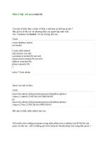
13.2.2 Invoking PLI Tasks
Once the user-defined task has been linked into the Verilog simulator, it can be
invoked like any Verilog system task by the keyword $hello_verilog. A Verilog
module hello_top, which calls the task $hello_verilog, is defined in file hello.v as
shown below.
module hello_top;
initial
$hello_verilog; //Invoke the user-defined task $hello_verilog
endmodule
Output of the simulation is as follows:
Hello Verilog World
13.2.3 General Flow of PLI Task Addition and Invocation
We discussed a simple example to illustrate how a user-defined system task is
named, implemented in terms of a user-defined C routine, linked into the
simulator, and invoked in the Verilog code. More complex PLI tasks discussed in
the following sections will follow the same process. Figure 13-2
summarizes the
general process of adding and invoking a user-defined system task.
Figure 13-2. General Flow of PLI Task Addition and Invocation