SolidWorks 2010- P4 pps
Bạn đang xem bản rút gọn của tài liệu. Xem và tải ngay bản đầy đủ của tài liệu tại đây (673.39 KB, 30 trang )
Explore the Anatomy of a Part
59
NOte
The filter function in the FeatureManager design tree acts the
same in assemblies, but it also filters out components in both the tree and
the graphics area.
Sensors
Below the filter bar and the model name in the FeatureManager design tree is
the Sensors folder. Sensors are used to monitor certain parameters in your part
or assembly such as mass properties, measurements, interference detection, and
simulation data. As the values of the sensors deviate from the specified limits,
an alert will be displayed.
Annotations
Directly below the Sensors folder is the Annotations folder. In part files, anno-
tations act like dimensions that can be placed directly onto the part model to
satisfy the requirements of ASME Y14.41-2001. Placing dimensions and annota-
tions directly onto the model eliminates the need to create paper drawings.
Material
Depending on what you are planning to do with the part model, you may find it
necessary to apply a material. In some cases, it may not be necessary to apply a
material to a part, but if you are planning to perform a simulation, obtain mass
properties, or reference the material using custom properties, it will be neces-
sary to apply a material to a part. When a material is applied to a part, the mate-
rial is displayed in the FeatureManager design tree.
O
You can find more
information regard-
ing the various
ASME standards
referenced in
this book on the
American Society
of Mechanical
Engineers website at
www.asme.org.
505434c02.indd 59 1/26/10 2:35:04 PM
Chapter 2 • Learning the Basics
60
Planes
By default, every part and assembly has three planes when you create a new part: the
front plane, the top plane, and the right plane. These three planes intersect at the
origin in the part environment. The planes that are shown in the FeatureManager by
default can be renamed and hidden, but they cannot be deleted.
The planes that are shown in the FeatureManager can be seen in the graphics
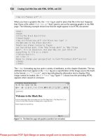
area, as shown in Figure 2.11, if the plane is set to Visible.
FIGURE 2.11 Planes in graphics area
You can see the planes in the graphics area by making them visible in the
FeatureManager. To hide or show a plane, do the following:
1. In the FeatureManager, select the plane to be shown in the graphics area.
2. In the context toolbar, select Show to display the plane. When the
plane is set to Show, the icon in the FeatureManager will be shown as
a solid yellow color.
3. To hide the plane, select the plane again, and select Hide from the
context toolbar.
505434c02.indd 60 1/26/10 2:35:05 PM
Explore the Anatomy of a Part
61
NOte
If the plane does not appear in the graphics area after select-
ing Show in the context toolbar, the visibility of all planes in the graphics
area may be set to Hidden. To show planes in the graphics area, select View
Planes in the Hide/Show Items flyout on the Heads-up View toolbar.
Origin
The origin shown in the FeatureManager design tree represents the origin of the
graphics area. If the origin is not visible in the graphics area, you can select the
origin in the FeatureManager design tree, and 0,0,0 will be highlighted in the
graphics area.
Features
We have reached the most important part of the FeatureManager design tree,
the tree. The features listed in the tree are the steps taken to create the base
plate model. Since the example is a really simple part model, there are only a
couple of features that were used to create the part. However, in some of the
more complex models, it is not unheard of to have a feature tree with hundreds
of features.
The first feature in the tree is the base feature. This is usually created using
a sketch or series of sketches that is then extruded, revolved, swept, or lofted.
The icon shown denotes the feature type that was used to create the feature. For
this example, the base feature of the Base Plate was created using Extruded Base/
Boss. The text next to the icon is the name of the feature that was automatically
generated on creation. The name consists of the feature type followed by a num-
ber that is sequentially incremented every time a similar feature is created.
tIp
You can rename features in the FeatureManager design tree by
slowly clicking the feature name twice and entering the new name when the
old one is highlighted.
505434c02.indd 61 1/26/10 2:35:05 PM
Chapter 2 • Learning the Basics
62
Selecting a feature in the feature tree will highlight it in the graphics area. This
is because the FeatureManager design tree and the graphics area are dynamically
linked. Selecting features, sketches, drawing views, and construction geometry in
either the FeatureManager design tree or the graphics area will highlight it in the
other. Let’s give it shot:
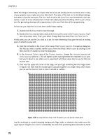
1. In the FeatureManager design tree, click the feature named Extrude1.
2. The entire part in the graphics area will be highlighted, except for the
four screw holes because they were created with separate features, as
shown in Figure 2.12.
FIGURE 2.12 Using FeatureManager design tree to highlight features in
the graphics area
3. What if you had hundreds of features listed in the FeatureManager
design tree and you were not exactly sure where the one you wanted
was listed? If you select the feature in the graphics area, it will be high-
lighted in the tree. Select one of the screw holes in the graphics area.
505434c02.indd 62 1/26/10 2:35:05 PM
Explore the Anatomy of a Part
63
4. The counterbored hole feature that was created using the Hole
Wizard will be highlighted in the FeatureManager design tree, as
shown in Figure 2.13.
FIGURE 2.13 Selecting a feature in the graphics area to find it on the
FeatureManager design tree
Now that you know how to determine which feature listed in the FeatureManager
design tree relates to the actual feature on the part model, what can you do with
that information? Well, one of the things you can do is see the sketch that was used
to create the feature. Sketches are normally 2D open or closed profiles that are used
to create extrusions, cuts, revolves, sweeps, and lofts. In Chapter 3, “Creating Your
First Part,” you will dig deeper into creating sketches. For now, follow these steps to
view a sketch:
1. In the FeatureManager design tree, click the small plus in front of the
icon for the Extrude1 feature.
2. The sketch that was used to create the Extrude1 feature will now be
shown below the feature. This sketch is named Sketch1 since it was
the first sketch that was created in this part.
3. At this point in the book, we won’t cover how to open and modify the
sketch, but it is possible to just view the sketch in relation to the part
model and even see the dimensions that were used to fully define
the sketch. Select Sketch1 in the FeatureManager design tree with a
single click.
4. The sketch will now appear in the graphics area, as shown in
Figure 2.14.
505434c02.indd 63 1/26/10 2:35:05 PM
Chapter 2 • Learning the Basics
64
FIGURE 2.14 Viewing a sketch that makes up a feature
NOte
The dimensions that were used to define the sketch will be
shown with a single click only when Instant3D is enabled. Instant3D can
be turned on by selecting the Instant3D button on the Features tab in the
CommandManager. If you do not want to enable Instant3D, the dimensions
for the sketch can still be shown by double-clicking the sketch.
Rollback Bar
To extend the time machine metaphor even further, the rollback bar allows you
step back in time and see the individual steps that were performed to create a
model. The rollback bar is a line below the features in the FeatureManager design
tree that can be dragged up or down in the feature tree. Any features that exist
below the rollback bar act as if they have not been created yet. To get a better
understanding of the concept, it is probably better to try it for yourself:
1. In the Base Plate part model, move the mouse pointer directly above
the line that is below the feature tree. When the mouse pointer
changes to show a hand, press and hold the left mouse button.
505434c02.indd 64 1/26/10 2:35:06 PM
Explore the Anatomy of a Part
65
2. While still holding the left mouse button, drag the rollback bar above
the counterbored hole feature, and release the mouse.
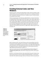
With the rollback bar above the counterbored hole feature, the holes are removed
from the plate, as shown in Figure 2.15. This is because, based on the placement of
the rollback bar, they haven’t been created yet.
FIGURE 2.15 Using the rollback bar to view an earlier state of a part
One advantage to being able to step back in your feature tree is that it is pos-
sible to insert new features above features that have already been created. Later
in this book, we will be working more with changing the order of features in the
FeatureManager design tree. So, for the time being, return the rollback bar to
its original position below the feature tree by dragging it back down.
Display Pane
The display pane is an extension of the FeatureManager design tree that pro-
vides you with a quick view of the display settings that are applied to the indi-
vidual features, entire part, and bodies. The display pane is available in parts,
505434c02.indd 65 1/26/10 2:35:06 PM
Chapter 2 • Learning the Basics
66
assemblies, and drawings, but changes to the display pane can be applied only in
parts and assemblies.
1. To show the display pane, click the chevron on the top-right of the
FeatureManager design tree.
2. The display pane will appear to the right of the FeatureManager
design tree.
The display pane is broken down into four columns, as shown in Figure 2.16.
Each column is described next.
Display ModeHide/Show
Appearances
Transparency
FIGURE 2.16 Display pane columns
Hide/Show In the Hide/Show Column, some items in the FeatureManager dis-
play tree can have their visibility status changed, including solid bodies, planes,
and sketches. Figure 2.17 shows an example of changing the visibility of a sketch.
The actual features, such as extrusions and sweeps, cannot be hidden individually.
FIGURE 2.17 Showing sketch in display pane
Display Mode In part files, the Display Mode column applies only to solid
bodies and is used to display and change whether the solid body is shown with
one of these settings: Wireframe, Hidden Lines Visible, Hidden Lines Removed,
Shaded With Edges, or Shaded. Figure 2.18 shows changing the display mode
505434c02.indd 66 1/26/10 2:35:06 PM
Explore the Anatomy of a Part
67
of the solid body for the Base Plate model. Setting the display state this way
will override the display state settings in the Heads-up View toolbar. To allow
the state to be specified by the Heads-up View toolbar, set the state to Default
Display in the FeatureManager.
FIGURE 2.18 Changing the display mode in the display pane
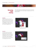
Appearances Appearances are used to add the look of certain materials to the
entire part, body, or individual features. Items in the FeatureManager design tree
that have an appearance applied to them will show a color block that reflects the
color of the appearance. If there is no block shown in the Appearances column,
then there has not been an appearance applied to the feature. Figure 2.19 shows
that a matte aluminum has been applied to the Base Plate solid body. Later in the
book, we will show you how to apply appearances to parts, bodies, and features.
FIGURE 2.19 Appearances in the display pane
Transparency Parts, bodies, and features can be made to be transparent, giving
a glass appearance that allows you to view internal features or features or bod-
ies that might otherwise be obscured. Items in the FeatureManager design tree
that have been made transparent will show an icon to represent that the item is
505434c02.indd 67 1/26/10 2:35:06 PM
Chapter 2 • Learning the Basics
68
transparent. Figure 2.20 shows that the Extrude1 feature has been changed to
be transparent. Applying transparencies to features and parts will be discussed
later in the book.
FIGURE 2.20 Changing transparency in the display pane
Hidden Tree Items
There are a number of tree items that you currently do not see in the Base Plate
part. This is because they are set to be automatically hidden unless they are
being used within the model. For example, the Equations folder is not visible in
the FeatureManager design tree unless equations are being used in the model.
You can adjust the visibility of tree items to always be hidden, visible, or auto-
matic. Here is how to do it:
1. Right-click while the mouse pointer is anywhere inside the
FeatureManager design tree including on any item in the tree. In the
right-click menu, select Hide/Show Tree Items (Figure 2.21).
FIGURE 2.21 Selecting Hide/Show Tree Items
505434c02.indd 68 1/26/10 2:35:06 PM
Explore the Anatomy of a Part
69
2. In the System Options window, click the down arrow next to the tree
item for which you want to adjust its visibility (Figure 2.22).
FIGURE 2.22 Adjusting the visibility of tree items
The Automatic setting means items will display in the design tree
only if they exist. For instance, if the tree item is set to Automatic
and it is not shown in the FeatureManager design tree, then it does
not currently have any items to be displayed.
3. Sometimes it is helpful to turn on the visibility of some folders or
even turn off tree items that you do not use often, such as the sen-
sors. If you want to hide the Sensors folder, select Hide in the drop-
down menu. Click OK to close the System Options tab.
The Sensors tree item will now be invisible in the FeatureManager
design tree.
NOte
For the sake of the examples shown earlier in this chapter, the
Solid Bodies folder was set to Show when the part was created. Normally
this folder is set to Automatic in the Hide/Show Tree Items and would not be
visible when only one solid body is present in the model.
505434c02.indd 69 1/26/10 2:35:06 PM
Chapter 2 • Learning the Basics
70
PropertyManager
Above the FeatureManager design tree are additional tabs that display more man-
agers, each of which has its own set of tasks. The tab next to the FeatureManager
design tree is the PropertyManager tab. The PropertyManager is where values
are entered or changed when initiating commands or selecting entities in the
graphics area. Instead of selecting the PropertyManager tab, it will automatically
be displayed when you select an entity or initiate a command. Figure 2.23 shows
the PropertyManager when a dimension is selected in the graphics area. Each
command and entity has its own PropertyManager, and you will be learning
about them individually as you begin to build the lamp project later in the book.
FIGURE 2.23 Dimension PropertyManager
ConfigurationManager
Next to the PropertyManager tab is the ConfigurationManager. The
ConfigurationManager is used to create, select, and view configurations in
parts and assemblies. Configurations are variations of a part or assembly such
as dimensional differences of features within the same part. A good example
would be a tube that can be produced with different diameters or lengths using
only one part file. We will be going more into configurations in Chapter 9,
“Modeling Parts Inside a Subassembly.”
DimXpertManager
The DimXpertManager provides access to the tools necessary for applying dimen-
sions and tolerances to the actual 3D model instead of using drawings. ASME
Y14.41 and ISO 16792:2006 are both standards that allow for the annotation of
505434c02.indd 70 1/26/10 2:35:07 PM
Use Assemblies
71
3D geometry to be used in lieu of paper drawings. We will not be covering using
DimXpertManager in this book, but we encourage you to look into it once you
become proficient at using SolidWorks.
Use Assemblies
An assembly is a collection of parts, features, and subassemblies that are mated
together to create the end product. In SolidWorks, there are two approaches in
creating assemblies: top-down and bottom-up.
The top-down design approach to creating an assembly means that parts are
created in context to the assembly that will dynamically update as referenced
geometry in the assembly is updated. The benefit of using the top-down approach
is that as referenced parts are updated, the changes are propagated to the other
parts in the same assembly. The drawback to creating top-down assemblies is
that changes to one part can cause errors in other parts in some cases.
The bottom-up design approach to creating an assembly means that the parts
are made independently and assembled together in the assembly using mates.
Changes made to the individual parts will not affect other parts in the assembly.
The advantage to the bottom-up approach is that changes to one part will not
cause errors in other parts, except for the occasional mate error in the assembly.
The drawback to the bottom-up approach is that each individual part will need to
revised independently as the design progresses, and this leaves open the chance
of missing an important change in another component of the assembly.
NOte
Both the top-down and bottom-up assembly techniques have
their own pros and cons; however, learning and using both will dramatically
affect your efficiency in SolidWorks, and you will be using both approaches
in subsequent chapters once you begin building the lamp project.
Before moving on the following sections, you need to open the assembly files
that you should have downloaded from the companion website by doing the
following:
1. If you have not done so already, close the part model used in the pre-
vious sections by clicking the Close icon located in the upper-right
corner of the graphics area.
2. To open the Base Plate assembly, click the Open button located on
the toolbar.
505434c02.indd 71 1/26/10 2:35:07 PM
Chapter 2 • Learning the Basics
72
3. In the Open window, navigate to the folder that contains the files
that you downloaded from the companion website, and select the file
named
Base Plate Assembly.SLDASM.
4. Click Open.
FeatureManager Design Tree in Assemblies
The FeatureManager design tree in an assembly has many of the same elements
as in a part file, including sensors, annotations, planes, and the origin. The pri-
mary difference between the FeatureManager for parts and the FeatureManager
for assemblies is that instead of just features listed, the tree displays components,
subassemblies, and assembly-level features such as holes and cuts.
The FeatureManager design tree for an assembly displays the top-level com-
ponents and subassemblies that make up the assembly. The icons shown in the
FeatureManager reflect the type of component or feature used in the assembly.
The features that make up a component in the assembly or the components in a
subassembly can be viewed and modified from the FeatureManager design tree.
Display Pane
The display pane in assemblies is very similar to the display pane in part models,
as shown in Figure 2.24. Changes applied to the parts in the display pane are
applied only at the assembly level and do not propagate to the part level.
FIGURE 2.24 Display pane in an assembly
505434c02.indd 72 1/26/10 2:35:07 PM
Use Assemblies
73
Hide/Show In assemblies, each component can be hidden or shown via the dis-
play pane. Once hidden, the component can be selected once again to be shown.
Display Mode Components and component solid bodies can have their display
mode adjusted in the display pane to either Wireframe, Hidden Lines Visible,
Hidden Lines Removed, Shaded With Edges, Shaded, or Default Display.
Appearances Applying an appearance at the assembly level allows you to add
color, texture, or a RealView material to a part, superseding any appearance that
was added at the part level. Figure 2.25 shows how the Base Plate in the assem-
bly has a different color applied at the assembly level than what was added at the
part level. The lower-right triangle represents the color of the part at the part
level, and the upper-left triangle shows the color applied in the assembly.
FIGURE 2.25 Appearances of components in display pane
Transparency As in part models, components in an assembly can be made to
be transparent, giving a glass appearance that allows you to view internal fea-
tures or features or parts that might otherwise be obscured. Components in the
FeatureManager design tree that have been made transparent will show an icon
to represent that the item is transparent.
Mates
At the very bottom of the FeatureManager design tree in assemblies, as shown
in Figure 2.26, is the Mates folder. This is where you will find the mates that
were used to create the assembly. In Chapter 6, “Creating a Subassembly,” you
will be introduced to using the various mates available in SolidWorks.
O
Adjusting the
Display Mode setting
of individual com-
ponents will come
in handy when you
create display states,
which are described
in later chapters.
505434c02.indd 73 1/26/10 2:35:07 PM
Chapter 2 • Learning the Basics
74
FIGURE 2.26 Mates in an assembly
Tell a Story with Drawings
The drawing environment shares many of the same elements with parts and
assemblies. Just like with parts and assemblies, the drawing environment uses
the graphics area, FeatureManager, display pane, and PropertyManager, but they
do act a little differently.
Graphics Area
The graphics area of a drawing is a 2D plane that represents a sheet of paper that
is always normal to the screen. Unlike the graphics area in a part or assembly,
the view cannot be rotated. In fact, the Rotate tool is not even available while
you are editing a drawing except in drawing views, but we will get to that later.
Later in this book, you will be taking a closer look at creating drawings, so here
we’ll give you a quick overview of the different areas that make up a drawing.
Sheet Format
Back in the day of drawing boards and T squares, drafters would often use vellum
sheets preprinted with title blocks. This would save the drafter valuable time that
would otherwise be used drawing the title block every time they created a draw-
ing. In SolidWorks, when creating a new drawing, the sheet format contains the
title block associated with the selected drawing template. This is one reason why
the drawing template and sheet format are often confused. Figure 2.27 shows the
sheet format that can be seen when editing the sheet of a drawing.
NOte
A sheet format contains items that are part of the drawing sheet,
but a drawing template can contain the sheet format, revision table, tables,
notes, predefined drawings views, and so on.
505434c02.indd 74 1/26/10 2:35:07 PM
Tell a Story with Drawings
75
FIGURE 2.27 Drawing sheet format
Most organizations will have a variety of sheet formats they will use based on
the sheet size and differences in title blocks. As you are creating a drawing, you
can easily switch between sheet formats in the sheet properties. This is often the
case when you are creating a drawing for a particular sheet size and you later
discover that you need a larger or smaller sheet. Later in the book, we’ll show
how to switch between sheet formats.
Drawing Views
Drawing views act like windows that show a 2D view of your part or assembly.
These views are linked to the part or assembly that was used to create them, allow-
ing the view to update as the geometry is changed. A drawing view can show one
of the orthographic projections or isometric views of your part. Drawing views can
be moved in relation to a projected view or be made to move independently any-
where in the drawing, including off the drawing sheet altogether. Drawing views
can also be set to any scale, but it is good practice to have the view scale be based
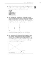
on the sheet scale. Figure 2.28 shows the isometric view of the base plate.
Annotations
The term annotations is an all-encompassing term that includes dimensions,
notes, tables, balloons, and so on. Figure 2.29 shows some annotations that have
been applied to a drawing view. Some annotations can be inserted automatically
when creating drawing views, but others are added manually to the drawing.
Each of the annotations types will be explained in more detail in future chapters.
O
An annotation is
anything used to
better tell the story
of the drawing that
the drawing views
by themselves can-
not do.
505434c02.indd 75 1/26/10 2:35:07 PM
Chapter 2 • Learning the Basics
76
FIGURE 2.28 Drawing view in a drawing
FIGURE 2.29 Annotations in a drawing
Sheet Tabs
If you have ever created drawings, then you would know that it is often difficult to fit
all the necessary information into one sheet of a drawing. Luckily with SolidWorks,
it is not necessary to create a different drawing for each drawing sheet. Using tabs, a
single drawing can have multiple sheets easily accessible at the bottom of the graph-
ics area. By clicking the sheet tabs, as shown in Figure 2.30, you can easily switch
between each drawing and even add and remove sheets. If you hover your mouse
pointer over a sheet tab, you will be presented with a preview of the sheet. This can
be a good time-saver if you have many sheets, since you will not need to activate
each sheet to find the one you want.
505434c02.indd 76 1/26/10 2:35:07 PM
Tell a Story with Drawings
77
FIGURE 2.30 Multiple sheet tabs in a drawing
FeatureManager Design Tree
The FeatureManager design tree for the drawing environment is similar to what
you find in parts and assemblies, except that instead of parts or features being
shown, it shows a list of items on the drawing. In addition to displaying blocks
and annotations on the drawing, the FeatureManager design tree shows the
drawing sheets. The sheets that exist in a drawing are shown with an icon and
the sheet name.
Figure 2.31 shows how expanding the sheet in the FeatureManager will dis-
play the sheet format and drawing views contained therein. As you expand the
drawing views, the referenced models will be displayed.
If the drawing view is a generated view, like a detail or section view, expanding
the view in the FeatureManager will display additional information such as the
section line or detail circle. Figure 2.32 shows how a generated view, in this case
a section view, contains the file references as well as the section line.
The display pane in a drawing differs from that of parts and assemblies in that
changes cannot be applied to the display pane. The display pane will display the
type of view that is being used in the drawing and the display mode for each
view, as shown in Figure 2.33. To be honest, you won’t need to view the display
pane in your drawings unless you quickly want to view the display mode that is
used on all your views.
505434c02.indd 77 1/26/10 2:35:07 PM
Chapter 2 • Learning the Basics
78
FIGURE 2.31 Drawing views and references in FeatureManager
FIGURE 2.32 Generated views in FeatureManager
FIGURE 2.33 Drawing display pane
PropertyManager
The PropertyManager in the drawing environment will be heavily used during
the drawing creation process. Nearly every aspect of creating a drawing relies
on the PropertyManager, although in
➢
SolidWorks 2010 the reliance on the
PropertyManager when specifying dimension parameters has been relieved with
505434c02.indd 78 1/26/10 2:35:07 PM
Are You Experienced?
79
the introduction of the dimension palette. To access the PropertyManager, there
is no need to select the tab; instead, select any entity in the drawing area. In the
PropertyManager, you will be able to view or modify the properties for the item you
selected. Figure 2.34 shows the PropertyManager when a section line is selected in
the drawing.
FIGURE 2.34 PropertyManager in a drawing
Are You Experienced?
Now you can…
Open various documents in SolidWorks
Use the reference triad to change views
Show/hide the origin in parts and assemblies
Use the rollback bar in parts
Hide/show the display pane
Recognize the various elements of the FeatureManager design tree
Recognize the differences and similarities between parts, drawings,
and assemblies
505434c02.indd 79 1/26/10 2:35:08 PM
505434c02.indd 80 1/26/10 2:35:08 PM
Chapter 3
Creating Your
First Part
Save the Model
Set the Document Properties
Create a Base Extrusion
Add an Extruded Cut
Add Boss Extrusions
Core Out the Part
Add Fillets and Chamfers
505434c03.indd 81 1/27/10 1:47:18 PM
Chapter 3 • Creating Your First Part
82
N
ow that you have spent some time going over the user interface of
SolidWorks and have explored the different document types, you can
begin creating your first project. For the rest of this book, you will be
modeling and creating drawings for a banker’s desk lamp. You will find
that your first project is something familiar so you are not overwhelmed by the
model itself. The project you are creating is just the basic parts and assemblies
that make up the lamp minus the wiring and electronics that would complete
the lamp.
The first step that you will take toward creating your desk lamp is creating a
new part document. SolidWorks comes with its own set of document templates
that you will be using throughout the book. If your organization has already
modified these templates to suit their own needs, you will still be able to follow
the examples provided in this book with little or no variation. To create a new
part document, do the following:
1. Click the New button located on the menu bar at the top of the
SolidWorks window.
2. The New SolidWorks Documents window, by default, offers three
SolidWorks document types: part, assembly, and drawing. Click Part,
and click OK.
An empty part file will open in SolidWorks.
Save the Model
Before moving on to creating your model, this is a good time to save the model,
which will allow you to name the part file. The first time you save a part, assem-
bly, or drawing, you will be prompted to select the location and name of the file
that will be created. Once the file is named, you will not be prompted again, and
you can save the changes any time you want without adding extra time to the
process.
To save the file and specify its location and filename, do the following:
1. Click the Save button located in the menu bar, or select File
➢ Save
from the menu.
2. The Save As window will allow you to specify the location on your
hard drive or the network location that you intend for the file to be
saved. Find the folder that you want to store the file in, and enter the
name of the file to be created. For this model enter the name Base,
Lamp in the File Name field, and click the Save button.
505434c03.indd 82 1/27/10 1:47:18 PM
Set the Document Properties
83
Set the Document Properties
Document properties are options that are document specific including detail-
ing, DimXpert, dimensions, units, line styles, and image quality. Once you set
the document properties, you will not change them, unless you need to update
them later during the design process. Changes are applied only to the current
active document. If you make changes to the property of a particular part docu-
ment, that change will not be reflected in other part documents.
NOte
Document properties are applied only to the selected document.
If you want changes to be applied to all future generations of a document,
you can apply document properties to the document templates.
You need to make sure that the document units have been set to meet the needs
of your design. Unless you are absolutely positive that you are using a template
with the proper units, you should make sure that these are set properly before
modeling by doing the following:
1. Click the Options button in the menu bar.
2. In the previous chapters, you made some changes in the system options
that affected the actual SolidWorks program. This time, select the
Document Properties tab at the top of the System Options window.
3. The very first screen you will see after selecting the Document
Properties tab will allow you to select the overall drafting standard
that will be applied to the document. Depending on what part of the
world you live in, different standards are used to control how dimen-
sions are shown and applied. In the United States, we use the ANSI/
ASME standard for the application of dimensions. Ensure that ANSI
is selected in the Overall Drafting Standard field.
4. Next, select Units in the section on the left of the window.
505434c03.indd 83 1/27/10 1:47:21 PM