Foundation Flash CS4 for Designers- P4 pps
Bạn đang xem bản rút gọn của tài liệu. Xem và tải ngay bản đầy đủ của tài liệu tại đây (1.35 MB, 30 trang )
70
CHAPTER 2
While this foliage is interesting, we suspect that few of you will actually want to use these vines in many
of your projects (sure, maybe once, but after that?). The value of this tool isn’t in its default settings,
but rather in how the tool works. The
Deco tool, as well as the Spray Brush tool introduced in the next
section, is part of a new infrastructure in Flash CS4 called procedural modeling, which is just a fancy
term for generating drawings with programming. In this case, Flash does all the programming.
So how can you make the
Deco tool more useful? Keep reading.
3. Double-click the Eraser tool to clear the stage.
4. Reselect the Deco tool and take a look at the Drawing Effect area in the Property inspector. You’ll
see a drop- down menu. That’s your ticket. Change that drop- down from
Vine Fill to Grid Fill.
At this point, you can use the
Deco tool as is, but it’s more interesting if you give the tool an existing
piece of artwork to play with.
5. Click the Edit button in the Drawing Effect area of the Property inspector. This opens a dialog box
that lets you select a symbol named
square from the library. Select square by clicking it, and
then click the
OK button to close the dialog box.
6. In the Advanced Options area of the Property inspector, change the Horizontal spacing and
Vertical spacing values to 0. This will tighten up the spacing between the repeated square sym-
bols you’re about to see. Make sure to experiment with these values later as you try this tool
on your own.
7. Click near the upper- left corner of the stage, and you’ll get something like the image shown
in Figure 2-20. Note that the resultant grid is grouped together as a single entity, which means
you can use the
Selection tool to move it around as a whole.
Figure 2-20. By using the Deco tool’s Grid Fill option, you can quickly create grids.
Use this technique to create interesting backgrounds, flags, quilts, or whatever else makes sense for
a grid layout. Using the
Deco tool is considerably less work than positioning those elements by hand!
71
CREATING ARTWORK IN FLASH
Remember that you can change the spacing between the symbol tiles, and you can select whatever
library symbol artwork you want by clicking the
Edit button before clicking the tool on the stage.
Ready for a truly versatile
Deco tool option?
8. Double-click the Eraser tool again to clear the stage.
9. Click the Deco tool and select Symmetry Brush from the drop- down list in the Drawing Effect
area of the
Property inspector.
10. Using the Edit button, verify that square is still your selected library symbol.
11. In the Advanced Settings area of the Property inspector, select Reflect Across Line in the
drop- down list.
12. Start clicking the stage with the Deco tool. Take care not to immediately
release the mouse. Instead, click and hold, and then drag around a bit to
see how that affects the symbol that is dropped onto the stage. Because
you’re in
Reflect Across Line mode, you’ll see a mirror image of your
clicking on the opposite side of a pivoting handle (see Figure 2-21).
13. After clicking a few times, hover over the top of the pivoting handle
(the end with the curved double- headed arrow). Click that end of the
handle and drag along a curve to rotate your mirrored artwork. Click
and drag the opposite end of the handle to reposition the whole she-
bang.
14. In the Property inspector, change Reflect Across Line to Reflect Across Point. You’ll see the drag-
gable handle turn into a draggable circle, and one of the “arms” of your mirrored artwork is
flipped (the mirroring is now up and down, as well as left and right).
15. Change Reflect Across Point to Rotate Around. This time, the mirroring increases many times. In
fact, the result looks something like a kaleidoscope ( Figure 2-22).
Figure 2-22. The Rotate
Around option lets you create
kaleidoscopic artwork.
16. As before, the curved double- headed arrow lets you rotate the artwork, and the opposite
circle lets you drag it around the stage. A new handle—a shorter one, with a
+ on the end—
lets you change the number of “arms” of your starfish. Click and drag the
+ circle clockwise or
counterclockwise to make the change.
Figure 2-21. The Reflect Across
Line option lets you create mir-
rored artwork.
72
CHAPTER 2
17. Let’s try one last tool option. Double- click the Eraser tool, and
then reselect the
Deco tool. Choose Grid Translation from the
Advanced Options area of the Property inspector. While you’re in
the
Property inspector, put a check mark in the Default shape option
in the
Drawing Effect area. You’ll use the default shape, rather than
the
square symbol from the library, which will give you a clearer
view of the handles provided by this option.
18. Click the stage to paint a series of square dots, which is the default
shape you just selected, as shown in Figure 2-23.
Remember that you could have chosen a symbol from the library, just as you
did to create the grid in step 5. In fact, the
Grid Translation option is a lot like
the
Grid Fill option you saw earlier in this exercise. The difference is that with
Grid Translation, you can actually modify the grid’s characteristics dynamically.
Notice that the draggable handles are reversed from their previous configuration. This time, the
curved double- headed arrow is the shorter handle, while the
+ handle is the longer one. In addition,
the grid has two such pairs of handles: one for each of the x and y axes.
In Figure 2-23, the bottom- left circle lets you drag around the whole grid. Dragging either
+ handle
away from (or closer to) that circle adds (or removes) dots or symbols for that axis. By dragging the
respective double- headed arrow, you change the angle of that axis, which means you can slant (that is,
skew) the grid along either axis, and then change your mind and slant it another way.
Experiment with the drag handles, and then take note of the
Test collisions check box in the Advanced
Options
area. Keep that configuration in mind when you’re using library symbols instead of dots. With
symbols, you’ll often find that the grid contains gaps. When that happens, it’s because your symbols
are overlapping. The
Test collisions setting keeps that from happening by removing overlapped sym-
bols. Deselect that option to suppress symbol removal.
Grid Translation isn’t the only option that features the Test collisions setting.
You’ll see it with other Deco tool options, and it does the same thing every time.
The Spray Brush tool
There is a new brush tool in the CS4 lineup, and it is seriously fun to use. It’s called the Spray Brush tool,
and like the
Deco tool, it’s part of the new procedural modeling framework. Here’s how to use it:
1. Open the Oln]u>nqod*bh] file in the Chapter 2 Atan_eoa folder.
2. Click the drop- down menu for the Brush tool and select the Spray Brush tool. The tool’s icon looks
like a can of spray paint. This should tell you that you are about to become a graffiti artist.
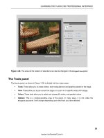
3. Open the Property inspector to see the tool’s properties, as shown in Figure 2-24. Set them as
follows:
Default shape: You can spray with a symbol in the library or with a series of dots by select-
ing
Default shape. If a symbol is not selected, you can’t deselect Default shape. You get the
dots.
Figure 2-23. The Grid
Translation option gives
you dynamically modifi-
able grids.
73
CREATING ARTWORK IN FLASH
Color: Click the color chip under the Edit button to change
your paint color. Set the color to
#000099 (blue).
Scale: Scrub across this value to make the paint drops wider.
Set it to
200%.
Random scaling: This gives you nonuniform paint drops.
Select it for this example.
Width, Height, and Brush angle: These configure the basic
shape of the brush. Leave these at their default settings for
now.
4. Click the mouse a couple times on the stage. Now click and drag
the mouse. Having fun? Double- click the
Eraser tool to clear the
stage.
5. Change the brush’s Width value to 20 and the Height value to
100 in the Property inspector. In addition, change the Brush angle
setting to
45 CW.
6. Click and drag. As you can see, you can create some pretty
interesting effects by changing the properties of the brush. With
the current settings, you get a tilted calligraphy brush.
Where this tool moves from neat to really cool is its ability to spray library items onto the stage. If you
open the library, you will see that we have included a graphic symbol called
pepper.
7. With the Spray Brush selected, click the Edit button in the Property inspector. This will open
the
Select Source Symbol dialog box. Click once on the pepper symbol, and then click OK. This
updates the available properties for the brush, allowing you to set scaling separately for width
and height, as well as choose additional random settings.
8. Use these values in the Property inspector:
Scale width and Scale height: 20%
Random scaling: Selected
Random rotation: Selected
Width and Height: 120
9. Click the mouse. Holy peppers! Click and drag around. You have just created a whirlwind of
tamales, as shown in Figure 2-25.
Given the right library symbols, we’re thinking this would make a great tool for snowstorms, starry
skies, windblown leaves, and so on.
Want to know a neat trick? If you use a movieclip as your source symbol, you
can even spray paint artwork that’s animated! Graphic symbols will do that,
too, but you’ll need to add frames in the parent timeline to let the graphic
symbol’s own timeline play out.
Figure 2-24. Spray Brush tool
properties
74
CHAPTER 2
Figure 2-25. Using the Spray Brush with a symbol
The Eraser tool
You can erase only vector artwork that isn’t protected inside a group of some kind. In other words,
if you try to erase a symbol, a text field, or something drawn in Object Drawing mode, it won’t work
unless you break apart the grouped objects.
Select the
Eraser tool or press the E key, and the following three modifiers appear in the Tools panel,
as shown in Figure 2-26:
Eraser Mode: This drop- down menu offers five choices, matching those for the Brush tool.
Eraser Shape: The choices in this drop- down menu let you select from a number of shapes for
the eraser.
Faucet: Select this, and you can erase an entire fill or line with one click. The hotspot is the drip
on the faucet.
Figure 2-26. The Eraser options
Here’s a quick way to erase the contents of an entire layer: double- click the
Eraser tool to clear that layer. As an exception to the rule, this trick even
erases grouped content in the relevant layer.
75
CREATING ARTWORK IN FLASH
The Pen tool
If you use Illustrator, Fireworks, or Photoshop, you are accustomed to using the Pen tool. The interest-
ing thing about this tool is that its roots aren’t found in the graphics industry. It started out as a solu-
tion to a tricky problem faced by the auto industry in the 1970s.
Computers were just starting to be used in some areas of car design, and the designers involved faced
a rather nasty problem: they could draw lines and simple curves, but squiggles and precise curves were
completely out of the question. The solution was to use a calculation developed by the mathematician
Pierre Bezier to produce what we now know as Bezier curves.
A simple curve is composed of a number of points. A Bezier curve adds two additional pieces of data
called direction and speed.
The
Pen tool draws Bezier curves. The two additional data bits are visually represented by the handle
that appears when you draw a curve with the
Pen tool. Here’s how to create a Bezier curve:
1. Select the Pen tool or press the P key. When you place the cursor on the stage, it changes to
the pen, and a small
x appears next to it.
2. Click and drag. As you drag, you will see three points on the line, as shown in Figure 2-27. The
center point, called the anchor point, is the start of the curve. The two outer points, called
handles, indicate the direction and degree of the curve.
Figure 2-27. The start of
a Bezier curve
3. Roll the mouse to another position on the screen, and click and drag the mouse. As you drag,
the mouse handles and the curve get longer, and the curve follows the direction of the handle,
as shown in Figure 2-28.
Figure 2-28. The curve shape changes
based on the length and direction of
the handle.
4. Click and drag a couple of more times to add a few more points to the shape.
5. Roll the mouse over the starting point of the shape. Notice the little o under the Pen tool (see
Figure 2-29)? This tells you that you are about to create a closed shape. Click the mouse.
76
CHAPTER 2
Figure 2-29. The shape is about to be closed.
A few other options available with the Pen tool allow you to edit your curves. If you click and hold the
Pen tool in the Tools panel, you will see there are three extra choices:
Add Anchor Point: Select this tool and click anywhere on the line to add an extra point.
Delete Anchor Point: Click an anchor point to remove it. The shape will change.
Convert Anchor Point: Click an anchor point, and the point will be converted to a corner point.
Unfortunately, this conversion does not go both ways. To get your curve back, switch to the
Selection tool and hover near a line that extends from the corner point. When you see the
curve cursor, drag out a bit of curvature yourself, and then switch back to the
Pen tool.
Prior to Flash CS3, these alternate
Pen tool modes were not available as separate tools. Instead, they
were presented as built- in features of an all-in- one
Pen tool. The distinct choices were certainly a wel-
come addition, but the old way ends up providing a decent workflow boost, even though hovering in
the right place takes a bit of practice. So take your pick. If you prefer using a single
Pen tool, notice
how cursor cycles among the following modes:
Add an anchor point: Use the Subselection tool, if necessary, to select an existing pen draw-
ing. Then, using the
Pen tool, hover over an existing line. Notice how the normal x under the
pen cursor becomes a
+. Click to add a new anchor point.
Delete an anchor point: There are two sorts of anchor points: curves and corners. Hover over
a corner point, and you’ll see the cursor acquire a little
Click to delete the anchor point.
Hover over a curved point, and you’ll need to click twice: once to convert the anchor to a cor-
ner point, and the second time to delete it.
Convert an anchor point: This converts curved anchors into corner points. In addition, the Alt
key temporarily converts the
Pen tool into the Convert Anchor Point tool.
Your turn: Trees grow at Lake Nanagook
In this little exercise, you are going to draw the tree that is used in the Lake Nanagook movie from the pre-
vious chapter. Along the way, we are going to introduce you to a couple of new tools. Let’s get to work.
1. Create a new Flash document.
2. Select Insert ° New Symbol. When the New Symbol dialog box opens, name the symbol Trees
and select
Graphic as its Type. Click OK to accept the changes and to open the Symbol Editor.
77
CREATING ARTWORK IN FLASH
Drawing the tree trunk
We’ll start with the trunk of the tree.
1. Select the Pencil tool and, in the Smooth mode, draw a stretched oval shape. This will be the
tree trunk. Select the shape on the stage and click the
Smooth button.
2. Select the Zoom tool, which looks like a magnifying glass, and click and drag over your shape.
When you release the mouse, the shape will be larger, so you will be able to manipulate it
more easily.
3. Switch to the Subselection tool and click your shape. You will see the vector anchor points and
handles. Manipulate the anchor points and handles to change the shape of the trunk. With
the
Selection tool, refine the shape by rolling the cursor over its edges, and when you see the
curved line under the cursor, drag the line segment inward or outward to alter the shape.
4. Double-click the Zoom tool on the Tools panel to zoom out to 100% view.
5. Switch to the Selection tool if necessary, click your shape, and in the Property inspector specify
these values:
Width: 17
Height: 37
X: 35
Y: 104.5
Stroke Color: #480000 (dark brown)
If you really need to see the decimal values while scrubbing, hold down the
Ctrl key. This allows you to scrub using decimal values.
6. In the Tools panel, set the Fill color to #480000 and select the Paint Bucket tool or
press the K key. Place the tip of the bucket in the hollow part of the shape and click
the mouse. The tree trunk will fill with the dark- brown color, as shown in Figure 2-30.
(An alternative would be to select the
Brush tool, and, using the Paint Inside mode,
paint the fill color into the shape.)
You are probably looking at the hex color value in the panel and think-
ing, “Hey, it’s hot text. I can scrub it to get the color?” Be our guest. Give it
a shot. Not easy, is it? When choosing color values, forget about scrubbing
and input them directly instead. Why? Because you have more than 16
million colors to scrub through.
7. Name the layer trunk and lock the layer.
With the trunk in place, next you’ll draw the pine tree.
Figure 2-30.
The tree trunk
is filled using
the Paint
Bucket tool.
78
CHAPTER 2
Drawing the pine tree
Think back to your youth and how you drew a pine tree. It was nothing more than a triangle. Here,
you’ll do the same and fill it with a gradient color.
1. Add a new layer named fir.
2. Select the new layer and select the Line tool in the Tools panel or press N on your keyboard.
The
Line tool draws straight lines and is great for drawing things like triangles.
3. Click and drag the tool on the stage to draw a line at an angle. Release the mouse, and the line
is drawn. Repeat this step two more times to draw the three lines.
4. When you reach the start point of the first line, a circle will appear, indicating you are about to
close the path. Click the mouse.
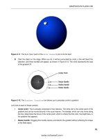
5. Select the Subselection tool and click the triangle. Notice how the stroke disappears and
the anchor points become visible. Select an anchor point with the
Subselection tool, as shown in Figure 2-31, and using either the mouse
or the arrow keys on your keyboard, move the points until the triangle
takes on the shape of a pine tree.
6. Switch to the Selection tool and roll the mouse to the bottom line of
your triangle. When you see the small curve under the pointer, drag
the line slightly downward. Your triangle should now look like a cone.
7. Double-click the shape to select it, and in the Property inspector, set its
width to
81 and its height to 114.
8. With the object selected, open the Color panel and select Linear from
the
Type drop- down menu.
9. Click the left crayon and set its color value to #002211 (dark green). Set
the color value of the right crayon to
#004433, which is a lighter green.
10. Select the Paint Bucket tool and fill the triangle. The gradient, shown in Figure 2-32, gives the
tree a bit of depth.
11. Switch to the Selection tool, double- click the stroke to select it, and press the Delete key. Move
the tree over the trunk and lock the layer.
Figure 2-32. Use a gradient to
give the tree some depth.
Figure 2-31. Use the
Subselection tool to
select and move move
anchor points.
79
CREATING ARTWORK IN FLASH
Adding pine needles
The final step in the process is to give your pine tree some needles. The key to this technique is to
match the gradient on the tree. It is a lot easier than you may think.
1. Add a new layer named needles.
2. Open the Color panel, select the Stroke color chip, and select Linear from the Type drop- down
menu. The gradient you just created is now in the
Stroke area of the Tools panel.
3. Select the Pencil tool and set the Stroke Width to 20 pixels in the Property inspector.
4. Click the Custom button in the Property inspector to customize your stroke. In the Stroke Style
dialog box, specify the following settings, as shown in Figure 2-33:
Type: Hatched
Thickness: Medium
Space: Very Close
Jiggle: Wild
Rotate: Medium
Curve: Medium Curve
Length: Random
Figure 2-33. You can set the stroke style for the Pencil tool.
5. Use the Zoom tool to zoom in on the tree. Draw four lines across the tree,
as shown in Figure 2-34.
This should also help you to understand how we did the grass that runs around
Lake Nanagook. We simply applied a smaller stroke width to the oval used for the
lake than the one for the pine needles.
A number of preset strokes are available from the
Property inspector’s Style drop- down list, to the left of
the Custom button.
Figure 2-34. Drawing a styled
stroke
80
CHAPTER 2
Working with color
So far, you have spent some time filling objects or strokes with either a solid or a gradient color.
Here, we will review the Color panel, and then discuss the color models and Color Picker.
The Color panel
As you’ve seen in the exercises so far, although the Color panel may look complicated, it is quite intui-
tive. The areas and controls are as follows (see Figure 2-35):
Type: This drop- down list allows you to create fills using solid colors, gradients, and even photo-
graphs.
Gradient Range: The two pointers, called crayons, allow you to condense or expand the colors’
range. Additional crayons can be added or removed, as described after this list.
Gradient Preview: Drag a crayon to the right or the left, and this area will change to show you
the result of the movement.
Alpha: Move this slider up and down to increase or decrease the opacity of the fill or stroke
color.
Swap Colors: Click this, and the fill and the stroke colors are swapped with each other.
No Fill: Click this icon, and the stroke or the fill color will be turned off. Click it again to restore
the stroke or fill.
Black and White: Click this icon, and the stroke color becomes black and the fill color becomes
white. This is basically a reset button.
Figure 2-35. The Color panel
Crayons are the workhorses of this panel. These controls, in an area called the crayon well, slide along
the
Gradient Range area and condense or expand the range of the gradient. Swap their positions, and
the gradient reverses. If you click anywhere between two crayons, you can add a third crayon (or
more), and add new colors to the gradient. To remove a crayon, drag it anywhere outside the crayon
well and release the mouse.
81
CREATING ARTWORK IN FLASH
Color models
The purpose of this section is to dig a bit deeper into the color models available to you as a Flash
designer and to show you a couple of really snazzy color techniques you can use in your day-to- day
workflow. What we aren’t going to do is get into color theory or take color down to its molecular
level. Entire books have been written on those subjects.
In Flash, you have three basic color models available to you: RGB, HSB, and Hexadecimal (the default).
Let’s briefly look at each one.
The RGB model is the computer color model. Each pixel on your computer monitor is composed
of a mixture of red, green, and blue lights. The value for each color is actually based on the old
black-and- white model for computers, where there were 256 possible shades of gray, from black to
white. The values started at 0 and ended at 255. The best way to imagine this is to think of 0 as being
“no light,” which means the color is black. Conversely, 255 is pure white. When it comes to the RGB
model, each pixel can have a color value that ranges from 0 to 255. If you are looking at a pixel with
values of 0 for red, 0 for green, and 255 for blue, you can assume the pixel is pure blue.
The letters in the HSB model represent hue, saturation, and brightness. Hue is the color, saturation is
the amount of the color or its purity, and brightness (Flash uses the other term for brightness: lumi-
nosity) is the intensity of the color. The ranges for each value differ in this model. Hue goes from 0 to
360; that’s one of 360 degrees around an imaginary wheel of color. Red starts at 0 (the same as 360).
Green is one third of the way around the wheel, 120. Blue is two thirds around, 240. To see your sec-
ondary colors, shift your travel around the wheel by 60 degrees: yellow is 60, cyan is 180, and magenta
is 300. Saturation and brightness are percentages. That pure blue value from the RGB model would
here be hue: 240, saturation: 100, luminosity: 100.
The RGB and HSB color modes may be switched in the top- right corner of the
Color panel, just below the x that closes the panel.
The Hexadecimal model is the one commonly used on the Web. In this model, the red, green, and blue
values for a pixel can include letters, which we realize may not make immediate sense. Hexadecimal
colors have six characters, which are actually three pairs of values: red, green, and blue. These hexa-
decimal characters are a bit different from the decimals we’re used to seeing. We humans, with ten
fingers, count in decimal notation. We start with nothing and keep adding one to the “ones column”
until we hit 9—that’s a range of ten values, 0 to 9. Add one more, and the ones column can’t go any
higher, so it resets to 0, while the “tens column” advances by one.
Computers aren’t so simple. Sometimes, they have 16 fingers on each hand, so their ones column goes
from 0 to 15. Columns can hold only one character at a time, so after 9, the value 10 is represented
by a letter—the letter A. 11 is represented by B, and so on, until 15, which is F. Add one more, and
the ones column can’t go any higher, so it resets to 0, while the tens column—actually, the “sixteens
column”—advances by one. If your brain hasn’t already turned to jelly, good, because even though
this doesn’t feel normal to us humans, it’s not so hard.
That 1 in the sixteens column and 0 in the ones column look like 10, but in hexadecimal notation,
that value is 16; 17 would be 11, 18 would be 12, and so on. A 10 in the ones column, as you now
know, would be A. So what we would call 26—that is, a 1 in the sixteens column and a 10 in the ones
82
CHAPTER 2
column—would be 1A. Follow that through, and you’ll see that FF refers to what we call 255 (that’s
15 in the sixteens column, a total of what we call 240, plus a 15 in the ones column). Therefore, in
the case of a completely blue pixel, the hexadecimal value would be #0000FF, which means zero red,
zero green, and the full 255 blue. Note the pound sign, #, which tells the computer, “Hey, read this as
a hexadecimal—rather than a decimal—number.”
So hexadecimal notation is really just another rehashing of the RGB model. It’s just a way to represent
a range from 0 to 255 in each of the primary colors.
The Color palette and Color Picker
When you click a color chip in Flash, the current Color palette, shown in Figure 2-36, opens. The color
swatches are arranged in hexadecimal groupings. As you run your cursor across them, you will see
the hex value for the swatch you are currently over. The colors on the left side of the Color palette
are referred to as the basic colors. These are the grays and solids used most often, although we don’t
know how often you’ll use the bright pink and turquoise at the bottom of the common colors!
Actually, there is a reason for the pink and turquoise on the left in the Color
palette. The left- hand column in that Color palette goes like this, from top to
bottom: six even distributions of gray, from black to white; then the three prima-
ries (red, green, blue); and finally the three secondaries (yellow, cyan, magenta).
These colors, by the way, follow this hex pattern: red, #FF0000; green, #00FF00;
blue,#0000FF; yellow, #FFFF00; cyan, #00FFFF; magenta, #FF00FF.
Figure 2-36. The current Color
palette
Another really useful feature of the Color palette is the ability to sample color anywhere on the com-
puter screen. When the Color palette opens, your cursor changes to an eyedropper and, if you roll the
cursor across the screen, you will see the hex value of the pixels you’re over appear in the
Hex edit
box, and the color will appear in the preview box. This is a relatively dangerous feature, because if you
click the mouse over a pixel on your screen, that will be the selected color.
Clicking the color wheel in the upper- right corner opens the Flash Color Picker. Figure 2-37 shows the
Windows version. The swatches in the top left are the basic system colors, and you probably noticed
the pane on the right with all of that color that sort of looks like the Northern Lights gone haywire.
This pane, called the color window, contains all of the color you can use in your movies. Click a color,
and you will see its RGB and HSB values as well as a preview of the color chosen. You can adjust that
color by moving the
Luminance slider up or down.
83
CREATING ARTWORK IN FLASH
Figure 2-37. The Flash (PC) Color Picker
How many individual colors are available to you in the color window? The answer is over 16 million.
One of the authors once answered this question, and the student who asked the question remarked,
“Is that all?” The author told him that was one seriously large number of crayons in his box, and
the student responded, “What if I want more?” The author thought about that one for a couple of
seconds and asked the student to imagine a crayon box with 16 million crayons. “If you have a box
of crayons, are they all given a color name on the label?” asked the author. The student replied, “Of
course.” The author then said, “OK, you have in your hands a box containing 16 million crayons. None
are labeled. Start naming them.” That ended the discussion.
How do we get 16 million colors? First off, the exact number is 16,777,216. At rock bottom, computers
use base 2 notation (a.k.a. binary), and the use of millions of colors is referred to as being 24- bit color.
Three primary colors comprise each pixel, and each color is defined by 8 bits (2 to the eighth power
is 256—aha, we’ve seen that number already). So that’s where the 24 comes from: three times 8 bits,
which is the same as saying 256 to the third power (256 256 256)—or 2 to the twenty- fourth
power.
Figure 2-38 shows the Mac version of the Color Picker. Although the Color Picker may look different
than the Windows version, it works in almost the same manner.
In the Mac- only color wheel, a color is chosen by clicking it in the wheel. If you want to adjust the
RGB values, click the
Color Sliders button at the top and select RGB Sliders from the drop- down menu.
Figure 2-39 shows the Color Picker after making this selection. The Mac color- picking options are
actually far superior to those on the PC. What the Mac can’t do is create multiple custom colors. You
will need to mix those individually.
84
CHAPTER 2
You don’t need to click OK on the Mac to save a color. You can drag and
drop a color from the preview area into the Custom Color boxes at the bot-
tom of the dialog box.
Figure 2-38. The Macintosh Figure 2-39. Choosing the sliders
Color Picker to change a color value
To add the color to your palette, either click the Add to Custom Colors button (PC) or click OK (Mac).
Sadly, things are not always a bowl of cherries for PC users. The custom color you just added appears
in the
Custom Colors area of the Color Picker. That’s the good news. The bad news is that if you add
another custom color, Flash will, by default, overwrite your first color. If you are creating a number of
custom colors, select the empty box before you pick your color.
Now suppose that you have a created a bunch of custom colors. Are they ready for use in all of your
projects? Not quite. They are not automatically saved when you close Flash. If you create some custom
colors and then close Flash, they will be gone—forever—when you return to Flash. So how do you
save your custom colors?
Creating persistent custom colors
Saving custom colors in Flash is not exactly up there in the category of “dead simple.” After you have
created your custom color, you need to add it to the main Color palette, and then save it as a color
set. Here’s a quick exercise to demonstrate how to do this:
1. Open the Color panel, select the Fill color, and select Solid as the fill type. Create the color
#B74867 (dusty rose), and make sure it is now the Fill color.
2. Click the menu in the upper- right corner of the panel to open the panel’s drop- down menu.
Select
Add Swatch, as shown in Figure 2-40.
85
CREATING ARTWORK IN FLASH
Figure 2-40. You start saving
a custom color by selecting
Add Swatch from the Color
panel menu.
3. Click the Fill drop- down menu to open the current Color palette. Your new swatch will appear
in the bottom- left corner of the swatches, as shown in Figure 2-41. You can add as many colors
as you wish, but we’ll stick with the one we are using here.
Figure 2-41. Your custom color now appears on the current Color palette.
4. Open the Swatches panel by selecting Window ° Swatches or pressing Ctrl+F9 (Cmd+F9).
5. When the panel opens, click the panel menu and select Save Colors, as shown in Figure 2-42.
The
Save As dialog box will open.
Figure 2-42. Saving a swatch
86
CHAPTER 2
6. Name your file iuBenopOap*_hn and, as shown in Figure 2-43, save it to ?6XLnkcn]iBehaoX
=`k^aX=`k^aBh]od?O0X?kiikjXBenopNqj (PC) or 8D]n`@nera:+=llhe_]pekjo+Bh]od?O0+
?kiikj+Benop Nqj+?khkn Oapo (Mac). The *_hn extension means the file is being saved as
a Flash Color Set (CLR) file. Click
OK to create the file and close the dialog box.
You don’t need to use the Flash application folder for your CLR files. Just put
them in a location where they will be handy. Some Flash designers stick them in
their Iu@k_qiajpo folder, and others put them in the current project folder.
Figure 2-43. Saving a color set
7. To load the color set, open the Swatches panel and select Add Colors from the panel menu.
Navigate to the folder containing the set and double- click it to add the set to Flash.
Yes, we agree that is a lot of work. Is there an easier way? In fact, there is. Why not do what the print
guys do and attach a color swatch directly to the file? Let’s assume you have a client who has six specific
corporate colors that must always be used. Create a graphic symbol containing squares filled with those
colors, and then simply put that symbol on the pasteboard (the area just outside the stage that doesn’t
show in the published SWF by default). Anytime you need the color, select the
Eyedropper tool and
sample it. If you are really lazy, don’t add it to the pasteboard and sample the color using the
Library
Preview
pane. If you use the colors in a lot of projects, you might even consider adding it to a shared
library along with the client’s logos and other common elements used in the client’s Flash projects.
The Kuler Color Picker
A couple of years back, Adobe introduced a small web- based color picker named Kuler. The whole
premise behind the application was to give the international design community an opportunity to
freely share custom color schemes with each other. Needless to say, the application was a hit, and it
87
CREATING ARTWORK IN FLASH
has been quietly added to practically every Adobe application containing a color palette. Flash is no
exception.
To access the Kuler color application, shown in Figure 2-44, select
Window ° Extensions ° Kuler. Scroll
through the list in the panel. If you see a combination, called a theme, you like, you can add it to your
Swatches panel. Just click the arrow to the right of the set’s name and select Add to swatches panel.
When you open the
Swatches panel (Window ° Swatches), you will see your selection has been added
to the bottom of the color chips.
If the Kuler panel shown in Figure 2-44 doesn’t appear, the odds are very
good that you’re looking at a dialog box that says you need to connect to
the Internet and that this is accomplished through the Flash preferences. At
the time this chapter was being written, there was nothing in the application
preferences in regard to online services. Instead, select Window ° Extensions
° Connections to open the Connections panel. Here, you can enter the same
username and password you use when logging in to the Adobe website (or
create an Adobe user account), which allows you to access online features in
component panels like the Kuler panel.
You can also edit a swatch in the panel. Click the right arrow and select Edit the Theme. The Create area
of the
Kuler panel will open, as shown in Figure 2-45. Select a swatch and start making changes. Once
you have a color or theme you like, click the
Save Theme button to name your theme. If you want to
return to the selection panel, click the
Browse button.
Figure 2-44. The Kuler panel Figure 2-45. Editing a Kuler theme
88
CHAPTER 2
For more information about using the Kuler application, click the About but-
ton and then click the Kuler link to visit the Kuler site, or visit the Kuler tuto-
rial at dppl6++gqhan*]`k^a*_ki+hejgo+pqpkne]h+.
Your turn: Play with color
Let’s try a few tricks with color. Two involve the standard use of a tool, but the other is right up there
in the realm of “That is waaay cool.”
Creating gradient effects
The first trick involves a gradient. Did you know Flash allows you to create a variety of gradient effects
with the click of a mouse? Here’s how:
1. Open a new Flash document and create a big rectangle filled using the leftmost gradient in the
Color Picker.
2. Switch to the Gradient Transform tool and resize the fill so it is much smaller than the rectangle.
When you shorten the gradient, the black areas and the white areas of the gradient become
larger. This is because Flash is filling the rectangle with the end colors. This process is called
overflowing.
3. Open the Color panel and click the Overflow drop- down menu. You will see
three choices (see Figure 2-46):
Extend: The last two colors in the gradient extend outward to fill the
shape. This is the default.
Reflect: The overflow area of the rectangle will be filled with repeating
versions of the gradient. Every other version is mirrored/reflected. Select
this, and the rectangle looks like stacked pipes (see Figure 2-47).
Figure 2-47. The Reflect overflow
Figure 2-46. The
Gradient Over-
flow options
89
CREATING ARTWORK IN FLASH
Repeat: The gradients aren’t reflected. The result is the “venetian blind” look. as shown in
Figure 2-48.
Figure 2-48. The Repeat overflow
If you really want to rock and roll with this technique, change the gradient type to Radial, reduce
the size of the gradient with the
Gradient Transform tool, and select the Repeat option. As shown in
Figure 2-49, the result resembles the background of the Looney Tunes logo.
Figure 2-49. That’s all folks.
Locking a fill
The next trick involves using a gradient fill to span across multiple unrelated objects. Here’s how:
1. Open the Cn]`eajpHk_g*bh] file in your Chapter 2 Atan_eoa folder. You will see a long rect-
angle filled with a gradient and a series of shapes under the rectangle.
2. Select the Eyedropper tool and click the gradient. The icon changes to a paint bucket with
a lock under it. This is the
Lock Fill feature of the Paint Bucket tool.
90
CHAPTER 2
3. Click once inside a shape, as shown in Figure 2-50. You’ll see that the gradient fill in the object
exactly matches the portion of the gradient directly above it.
Figure 2-50. Using the Lock Fill feature of the Paint Bucket tool
4. If you want to unlock the fills, click the Lock Fill button on the toolbar. If you click inside
a shape, Flash will regard the fill as being a new gradient, not a continuation of the one above
it, and the gradient color will change accordingly.
5. When you finish experimenting, close the file without saving the changes.
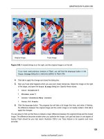
Using an image as a fill
The final technique is one a lot of Flash designers tend to overlook: using an image, as opposed to
a gradient or solid color, to fill an object. There are two methods of accomplishing this, and they each
have a different result. Let’s try them:
1. Open the Ei]caBehh*bh] file in the Chapter 2 Atan_eoa folder and open the Color panel.
2. Select Bitmap as the fill type. In cases where the FLA does not yet contain imported images, an
Import to Library dialog box will open at this point. In this sample file, an image already exists in
the
Library panel, so you’ll see the Import button instead.
3. If you would like to import an image of your own, click the Import button. If you go this route,
use the
Import to Library dialog box to navigate to an image. Select the image and click OK to
close the dialog box. Of course, you’re welcome to use the already- imported Opkkho*flc image.
The image will appear in the
Fill chip in the Color panel and in the Fill area of the Tools panel.
4. Select the Paint Bucket tool and click inside the object on the stage. It fills with several tiled
copies of the image, as shown in Figure 2-51.
5. Select the Gradient Transform tool to adjust the tiled image in various ways. Given the minus-
cule size of the tiles, you may want to zoom in first.
Now let’s see what happens with the second method:
6. Click the photo on the stage and select Modify ° Break Apart or press Ctrl+B (Cmd+B). The
image looks crosshatched. Why? Because you’ve essentially converted the photo into a shape
and filled it with its own bitmap, all in one go.
7. Select the Eyedropper tool and click once inside the photo. The image will appear in the Fill
color chip of the
Tools panel.
91
CREATING ARTWORK IN FLASH
Figure 2-51. Using a bitmap as a fill
8. Select the Paint Bucket tool and click the star shape on the stage. The image, shown in
Figure 2-52, now fills the star. Using this technique, the bitmap fill appears at actual size. If you
want to tile it, or otherwise manipulate it, use the
Gradient Transform tool.
Figure 2-52. Another way of using a bitmap as a fill
Now that you have finally had a chance to use a bitmap, let’s take a closer look at how such images
are used in Flash.
Using bitmap images in Flash
Up to this point in the book, you have been working with vectors. Though we have been telling you
they are the most wonderful things in the Flash universe, we are sure our photographer friends are
not exactly happy campers. Let’s face it—you are going to be using bitmaps in your workflow. You
can’t avoid them, and they are just as important as vectors. In fact, Adobe has really improved how
Flash manages images and integrates with Photoshop CS4, Illustrator CS4, and Fireworks CS4.
Now we will look at how you can use bitmap images in your workflow. We are going to talk about the
image formats you can use; cover how to import images from Photoshop, Illustrator, and Fireworks
into Flash; and even show you how to convert a bitmap image to a vector image in Flash. Let’s start
with the formats that can be imported.
92
CHAPTER 2
Importing image files into Flash
As an Adobe application, it is not surprising that Flash can import the following formats:
AI (Adobe Illustrator): This is the native Illustrator file format. This format allows Flash to
preserve the layers in your Illustrator document. The good news is that the Illustrator-to- Flash
workflow has had its molecules rearranged and turned inside- out—in a good way.
GIF (Graphic Interchange Format): This is the former standard for imaging on the Web. The
upside of this format is the very small file size. The downside is the Color palette is limited to
256 colors. These files come in two flavors: transparent and opaque. The increasing use of Flash
banner ads, with their strict file size requirements, has resulted in a resurgence of this format
on websites (yes, for use inside SWFs).
PNG (Portable Network Graphic): This is the native format for Fireworks. Think of PNG files
as a combination vector/bitmap file. This format supports variable bit depth (PNG- 8 and
PNG- 24) and compression settings with support for alpha channels. PNG files imported into
Flash from Fireworks arrive as editable objects and will preserve vector artwork in the file.
JPG or JPEG (Joint Photographic Experts Group): This is the current standard for web imag-
ing, and any image arriving in Flash will be converted to this format when the SWF is pub-
lished.
PDF (Portable Document Format): PDF is a cross- platform standard used in the publishing
industry.
EPS (Encapsulated PostScript): Think of this as a raw vector file.
PSD (Photoshop Drawing): This is the native Photoshop file format. A PSD image usually con-
tains multiple layers. Again, the workflow between Flash CS4 and Photoshop CS4 has under-
gone a profound change for the better.
PICT: This is a Macintosh format comparable to a BMP file on the PC.
TIF or TIFF (Tagged Image File Format): This is usually a high- resolution CMYK document.
A bitmap, or raster, image is nothing more than a collection of pixels. Bitmap images have taken a bit
of a bum rap in the Flash community because image files contain information that maps and remem-
bers the location of each pixel in the image. The result is often a large file size, which tends to go
against the grain in a community that chants: “Small is beautiful. Small loads fast.”
Use bitmaps when you need photos or lifelike images, when you need a screenshot, or when the
raster version of a drawing would actually demand less of the processor than its vector equivalent.
Generally speaking, a good rule of thumb is to look at a bitmap image and ask, “Could I draw this in
Flash?” If the answer is yes, you might want to consider doing exactly that.
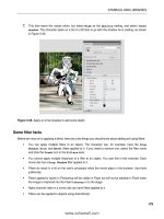
The best advice we can give you about bitmaps is to make them as small as possible—a process called
optimization—when exporting them from the originating application. That means reducing the Color
palette when feasible and scaling the image to the actual dimensions used in Flash, rather than using
Flash to resize the imported bitmap. For example, Fireworks CS4 contains an
Optimize panel, shown
in Figure 2-53, which allows you to compare the effects of various image settings for an image. In
Illustrator CS4, see if you can reduce the number of points in your shapes, and make sure you have
removed all of the stray points that aren’t connected to anything. In Photoshop CS4 and Fireworks
CS4, reduce the image size to fit the image size in Flash. These applications were designed to perform
these tasks; Flash wasn’t.
93
CREATING ARTWORK IN FLASH
Figure 2-53. Four- Up image optimization in Fireworks CS4 allows you to balance quality against image size.
Editing imported bitmaps
The decision is final. You need to use a bitmap and place it in Flash. Then you discover the color is all
wrong or something needs to be cropped out of the image. It needs to be edited. How do you do it?
Follow these steps:
1. Open a new Flash document and select File ° Import ° Import to Stage. When the Import dialog
box opens, navigate to the @]j_an*flc file.
2. Select the file and click Open to close the Import dialog box. The image will appear on the stage
and in the library, as shown in Figure 2-54.
Do not delete the image from the library. This is the original bitmap, and
deleting it will ripple through an entire project. If you mess up something on
the stage, delete the image on the stage.
3. Right-click (Ctrl- click) the image in the library to open the context menu.
4. Select Edit With. This will launch the Open dialog box, allowing you to navigate to the appli-
cation folder containing the application you will be using to edit the image. If you select
Photoshop CS4, the image will launch in Photoshop. When you make your changes, select
Edit
° Save
. When you return to Flash, the change made in Photoshop CS4 will be reflected both
in the image on the stage and in the library.
94
CHAPTER 2
Figure 2-54. Images imported to the stage are automatically placed in the library.
Fireworks CS4 has a rather cool feature called round- tripping. If you launch Fireworks CS4 as your edi-
tor, the image will open, and you will see a
Done button at the top of the canvas, as well as notification
that you are, indeed, “Editing from Flash,” as shown in Figure 2-55, Make your changes and click the
Done button. Fireworks will close, you will be returned to Flash, and the change will be visible on the
stage and in the library.
Figure 2-55. Round- trip editing between Fireworks and Flash