Photoshop CS3 for Screen Printers- P14 ppsx
Bạn đang xem bản rút gọn của tài liệu. Xem và tải ngay bản đầy đủ của tài liệu tại đây (1.43 MB, 30 trang )
.
Note:
As with the other filters, the dialog box is pretty intuitive. Click inside the
window to adjust the amount of distortion for this one, and use the – and +
buttons for zooming.
Noise
Noise adds or removes noise, or static, in a picture. Noise consists of
random pixels, and adding noise is useful when you need to apply random
pixels for a special effect. I can’t think of any reason why you’d want to
add noise to an image, unless you’ve got a picture of a TV set and want to
make it look like it’s broken, but I’m sure there’s a reason out there
somewhere!
On the flip side, reducing noise is generally helpful, and the
Despeckle and Dust & Scratches options can be used to reduce noise in
an image quite successfully. Be careful if you plan to screen print the
image though; the options in the Dust & Scratches dialog box can signifi
-
cantly blur the image and might not be useful.
366 Part IV / More Tools
Figure 20-3: Using the Twirl distort filter
Pixelate
Pixelated images are generally bad news, but if you’re looking for an
effect that will cause it, look no further. The Color Halftone filter takes
each channel of color, divides the image into rectangles, and then
replaces them with circles, similar to halftone screens. Crystallize uses
polygonal shapes, Facet uses block shapes, and Mosaic uses square
blocks. The other filters in this category do similar distortions.
Render
Render filters can be used to create cloud patterns, refraction patterns,
and light reflections in an image. The patterns that can be created can be
used as special effect backgrounds.
To create a background using a cloud pattern, for instance, start with
a new canvas and choose Filter>Render>Clouds. A cloud pattern will fill
the area using the foreground and background colors in the toolbox. You
can then apply other filters, such as Filter>Blur>Radial Blur or Filter>
Distort>Ocean Ripple for more effect.
Lighting effects let you create effects on RGB images using various
lighting styles. Using the Lighting Effects dialog box, as shown in Figure
20-4, you can create light from any direction, choose a spotlight, use
directional or omni light, configure intensity and focus, and more.
Chapter 20 / Special Effects 367
Figure 20-4: The Lighting Effects dialog box
.
Note:
Remember, you can apply filters to selections too, not just entire layers.
Sharpen
You’ve already been introduced to the Unsharp Mask command, and
there are other sharpen tools as well. Sharpening an image results in
cleaner edges, a less blurry image, and clarity improvement. Most
images can be sharpened quite a bit prior to screen printing them and
these filters should be used generously.
]
Tip:
Sharpen filters can be used to repair blurry photographs! They can also be
used after selecting a part of an image that’s blurry to sharpen only the
object that was in motion as you snapped the picture.
Sketch
These filters add texture to an image and can be used like the artistic
and brush strokes filters. Examples of sketch filters include Chalk &
Charcoal, Conté Crayon, Graphic Pen, Photocopy, Plaster, Torn Edges,
and Water Paper.
Stylize
These filters produce a painted or impressionistic effect by increasing
the contrast in the image. Figure 20-5 shows before and after pictures of
the OrangesII.jpg file. The filter applied is Filter>Stylize>Glowing
Edges. I use this filter quite a bit for creating images for printing on black
shirts—concert shirts, motorcycle shirts, etc.
368 Part IV / More Tools
If you’d like to experiment with this filter, open the OrangesII.jpg file
from the Chapter 20 folder on the companion CD, and apply the filter.
While you’re at it, try the Extrude, Solarize, and Wind filters.
Texture
Texture filters add texture to an image to make it look like you could
reach out and touch it and actually feel the texture that you’ve applied.
Texture options include Craquelure, which gives the image a cracked
look, Grain, Mosaic Tiles, Patchwork, Stained Glass, and Texturizer.
Stained Glass is a nice one to try if you need to create a logo for a church,
while Mosaic Tiles might work for a handyman.
Video
The Video filter options let you deinterlace and apply NTSC colors.
Video filters are used for creating artwork for video or TV.
Chapter 20 / Special Effects 369
Figure 20-5: Using the stylize filters
Other and Digimarc
Use Other to create your own filters to modify masks, make color adjust
-
ments, and offset a selection in an image. The filters you create can also
be saved for later use. Digimarc filters embed copyright information into
an image using a watermark. These topics are beyond the scope of this
chapter and book.
Extract
Extract lets you remove an object or objects from an image and works
when other options don’t (like the Background Eraser tool or the Magic
Eraser tool). With the Extract option, you can trace around an image to
select it for removal using a large highlighter-type pen, fill that area with
color, and extract it from the image. Sometimes it’s difficult to use the
eraser tools, especially when the image you’re working with is a photo-
graph and edges and colors are poorly defined or extremely similar in
color. The Extract tool works when you want to “Photoshop out” a per-
son in an image and place him or her in another photo, like what’s shown
later in Figure 20-7.
In what situations would the Background Eraser or Magic Eraser
tools not work?
To use the Extract tool:
1. Open an image that contains an object to extract. If necessary, from
the Layers palette, select the layer that you want to work with.
2. Choose Layer>Duplicate Layer to create a copy of the layer. You
will see the duplicate layer in the Layers palette.
3. To work only in a selected area, use the marquee tools to select an
area. This is optional.
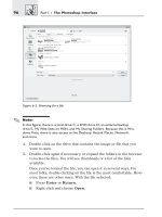
4. Choose Filter>Extract. You’ll see a dialog box similar to the one
shown in Figure 20-6.
5. Configure the options for Brush Size, Highlight, and Fill as you
would with any other dialog box. Highlight color is the color that
you’ll see when you trace around an image; Fill is the color that will
be used to define the extracted object. Brush Size defines the tip of
the tracing brush.
6. If the edge that you want to trace around contrasts highly with its
background, check Smart Highlighting.
370 Part IV / More Tools
7. Use the Zoom tool in the Extract dialog box to zoom in on the object,
andpresstheAltkeytozoombackout.UsetheHandtooltoview
other parts of the image while zoomed in.
8. Select the Highlighter tool. Use the mouse to trace completely
around the image and create a closed shape. Figure 20-7 shows how
I’ve traced around a person.
Tips for Tracing
n
When tracing around an object, position the brush so that you get a little of
the background and a little of the object itself.
n
If possible, draw completely around the object and enclose it by connecting
the beginning and ending points.
n
Use a larger brush for tracing around hair or other wispy edges. Use a smaller
brush for more defined areas.
n
Use the Eraser tool in the dialog box to erase a highlight drawn incorrectly.
Use Alt+Backspace on a PC to erase the entire highlight, or use
Option+Delete on a Mac.
Chapter 20 / Special Effects
371
Figure 20-6: Using the Extract command
9. Once the object has been traced around completely, select the Fill
toolfromtheleftsideoftheExtractdialogboxandfilltheareaby
clicking once inside it.
]
Tip:
To remove a fill, click again in the filled area with t he Fill to ol.
10. Click Preview. If the preview doesn’t yield the results you want and
you want to start over, change the Preview option in the Extract dia
-
log box from Extracted to Original.ThenpressAlt+Backspace on
a PC to erase the entire highlight, or use Option+Delete on a Mac.
11. If the extraction is off to a good start, you can edit it. Simply repeat
the steps above.
12. Locate the Clean Up tool and the Edge Touch Up tools in the Extract
dialog box. Use these tools to touch up the extraction.
372 Part IV / More Tools
Figure 20-7: Tracing and filling
13. To see how the object would look against a different background,
select a choice in the Preview area of the Extract dialog box. Under
Display, choose None, Black Matte, Gray Matte, White Matte, Other,
or Mask.
14. Click OK in the Extract dialog box when you are finished.
15. From the Layers palette, remove the eye icon from the original
image layer so that only the duplicate layer is showing. You’ll see
your extraction. (If you did not create a duplicate layer, this step isn’t
necessary.)
16. Use Edit>Fade Extract to add the final touches to the image.
While using the Extract tool is a bit more complex than using the lasso or
eraser tools, it’s also much more functional. Practice makes perfect, so
practice away!
Liquify
Liquify is a fun tool for making a mess of things. Beyond that, its useful-
ness lies in the ability to create awesome borders and special effects.
Use this filter to turn any piece of artwork into a gooey, liquid-looking
mess of colors, or use the colors as an edge for a rectangular design. To
experiment with the Liquify filter, open the file Trunk.jpg from the
Chapter 20 folder on the companion CD (it’s very colorful and perfect for
this project), choose Filter>Liquify, and follow along here:
1. In the Liquify dialog box, as shown in Figure 20-8, choose the Tw irl
Clockwise tool. You can select it from the left side of the Liquify
dialog box or by pressing R on the keyboard.
2. Choose a brush size in the Liquify dialog box that is approximately
the size of one of the squares on the trunk. Position the mouse over
a rectangular part of the trunk where red meets gold. Click and hold
to apply the twirl effect. Use the curser, now a circle, to create the
effect.
Chapter 20 / Special Effects 373
3. Select the Twirl Counterclockwise tool and repeat step 2.
4. Select the Pucker tool and repeat again. You’ll have to drag this tool
to get the desired effect.
5. Work your way through the rest of the tools.
6. Click Reconstruct to revert the image to its original, or click OK to
accept the changes. See Figure 20-9.
374 Part IV / More Tools
Figure 20-8: The Liquify dialog box
As with other tools and dialog boxes, the Liquify dialog box offers the
Hand tool and Zoom tool for panning the image and zooming in and out.
There are other options though, and you’ll want to experiment with
them. You can also choose show only the active layer in the dialog box by
deselecting Show Backdrop. However, only the active layer is actually
distorted.
Experiment with this tool to create borders and edges for photos that
you need to blend into shirts and other items. With practice, you can
make the object look like it’s moving as well. After applying a filter, try
Edit>Fade to see the effects that can be created after the transition.
Use your imagination!
The Fade Command
The Fade command appears in the Edit menu after a filter has been
applied and allows you to change the blending options for that filter. The
Fade command also appears after using a painting tool or an eraser or
after making a color adjustment. The Fade dialog box has two options:
one to change the opacity and another to change the blending mode.
Chapter 20 / Special Effects 375
Figure 20-9: Using the Liquify tool
The Fade command can be used on a single layer, a selection, or an
entire image. To work on a layer, choose that layer from the Layers
palette before applying the filter and working with Edit>Fade. To use it
on a selection, make the selection, apply the filter, and then use the Fade
command to edit the selection. The Fade command can only be used
immediately after applying a filter, eraser, painting tool, or color
adjustment.
Blending Modes
A layer’s blending mode determines how the layer’s colored pixels will
mix (relate) with the underlying pixels in the image. By default, there is
no blending of layers, but by choosing and applying a blending mode, you
can change this. When the blending mode is changed, the order of the
image’s composition is changed too. Blending modes are generally used
to create special effects, like adding soft light or hard light, or changing
the color, saturation, hue, luminosity, or other attributes of how the
layers can be combined.
6
Caution!
Remember to work in RGB mode. Some blends and filters won’t work in
Indexed Color, Lab, or CMYK mode.
Blending Mode Options
As with understanding filters, the best way to understand exactly what
blending modes do to an image or layer is to work through each type
using the same file. By doing so, you can see exactly how the layers
interact with different blending mode options. In this section, I briefly
describe what each blending mode does, and in the next section, show
you how you can apply the different modes to an image.
The following list does not contain all of the blending modes, as there
are quite a few! However, I’ve listed the ones I think you’ll use most
often, and you can experiment with the rest to find out what they do.
376 Part IV / More Tools
.
Note:
Blends can be between two layers, a layer and a selection, or a layer and
what is being painted on that layer with a tool such as a painting or erasing
tool. You’ll run across blending mode options often after painting or editing
an image.
n
Normal: Called Threshold when using bitmap or indexed color mode
instead of RGB mode, this mode is the default. The blend is natural,
and no distortion of pixels is added. The pixels added to the image
simply replace the underlying pixels.
n
Dissolve: Randomly distributes foreground pixels throughout the
layer or selected area and often gives a textured look to the image.
n
Darken: This mode changes pixels that are lighter than the fore
-
ground color. Pixels that are the same color or darker aren’t changed.
n
Multiply: Like the Darken mode, the Multiply mode darkens the
image. This is good for creating shadows, as it combines the existing
pixels with the foreground color in the toolbox when painting or
editing.
n
Linear Burn: The target layer’s colors are blended with the bottom
layer’s colors to decrease the brightness of the image. As with Color
Burn, no change occurs if the target layer is white.
n
Color Burn: Increases the contrast by darkening the colors on the
bottom layer of the image. If the layer is white, no change occurs.
n
Lighten: Looks at both the original color and the blend color and
chooses the lightest color as the result color. If a pixel is darker than
the blend color, it is replaced.
n
Screen: Produces a bleached look by blending the inverse of the
blend color and the original colors of the pixels in the image.
n
Color Dodge: Decreases the contrast of the layers in the image by
brightening the original colors in the image.
n
Linear Dodge: Increases the brightness in the layers in the image
by brightening the original colors in the image.
n
Overlay: Good for creating ghost-like images and effects, this mode
either multiplies or screens the colors, depending on the original col
-
ors in the image. The original color and the blend color are mixed.
Chapter 20 / Special Effects 377
n
Soft Light: Applies a soft light to the image, which can either
brighten or darken the image, depending on the original colors in the
image. If the image is light, the image is lightened similar to a dodge;
if the image is dark, the image is darkened similar to a burn.
n
Hard Light: Applies a hard light to the image, based on its original
color. It is similar to the Soft Light mode and is useful for creating
shadows.
n
Vivid Light: Burns or dodges the original color and the blend color,
depending on the darkness or lightness of the image. Lighter images
have their contrast decreased; darker images have their contrast
increased.
n
Linear Light: Similar to Vivid Light, except the brightness is
changed instead of the contrast.
n
Pin L ight: Replaces the original colors in the image based on its
blend color. The math is complicated, but the result is not. Generally,
this mode doesn’t produce anything usable (as far as I can tell).
n
Difference: Compares the blend color with the original color and
determines which is brighter. With that information, either the blend
color is subtracted from the original color or the original color is sub-
tracted from the base color. Blending with black produces no change.
n
Exclusion: Creates an effect similar to Difference mode, but with
less contrast in the resulting colors.
n
Hue: Combines the luminance and saturation of the original color
with the hue of the blend color.
n
Saturation: Combines the luminance and hue of the original color
with the saturation of the blend color.
n
Color: Combines the luminance of the original color with the hue
and saturation of the blend color.
n
Luminosity: Combines the hue and saturation of the original color
with the luminance of the blend color.
378 Part IV / More Tools
Applying a Blending Mode to a Layer
To understand what all of this means, open the file Blending Modes.psd
from the Chapter 20 folder on the companion CD. It has several layers
that will be perfect for applying blending and understanding what blend
-
ing modes do.
.
Note:
This file was created in a matter of minutes if you’d like to recreate it.
First, use the Magnetic Lasso to trac e around the bowl of oranges in the
OrangesII.jpg file, and then copy the bowl of oranges to the clipboard.
Create a new file, add a background, and paste the o ranges in. Add text
to the background.
1. With the Blending Modes.psd file open, select Window>Layer to
open the Layers palette if it is not available already.
2. In the Layers palette, select the Oranges layer by clicking on it
once. See Figure 20-10. (Notice that you can now select any tool to
work on this layer if desired; choose the Move tool to move the bowl
of oranges around on the image.)
Chapter 20 / Special Effects 379
Figure 20-10:
Choosing the layer
3. Double-click on the Oranges layer icon in the Layers palette to open
the Layer Style dialog box. Remember to double-click the icon, not
the layer name. Locate the Blend Mode option in the Blending
Options section and click the down arrow to see the list of options.
See Figure 20-11.
4. Make sure Preview is checked, move the Layer Style dialog box so
you can see it and the image, and choose the blending mode
Dissolve.
5. Repeat step 4 with the other blending modes. Luminosity gives a
nice effect for this image.
6. Work back through the blending modes that you liked, and this time,
change the opacity settings and experiment with the Styles options
on the left side of the dialog box. Click on the option to choose it and
configure additional settings.
If, after finding the perfect blending mode, you want to save it for future
use, you can. Simply click the New Style button in the Layer Style dialog
box and name your creation. It will then be available the next time you
need it.
380 Part IV / More Tools
Figure 20-11: The Blend Mode options
You can also work with the blending mode of the patterned layer. To
do this, you must change the order of layers in the Layers palette. Figure
20-10, shown earlier, shows the order of the layers in the Blending
Mode.psd file. Change it to what is shown in Figure 20-12 by dragging
the Blue Pattern Background layer up one position. Now, double-click on
the Blue Pattern Background layer to open up its Layer Style dialog box.
Work through the blending modes again with this layer.
Using the Gradient Tool
The Gradient tool can also be used to add an effect to a layer or image.
Gradients are gradual blends of multiple colors and can be radial, linear,
angle, reflected, or diamond shaped. Gradients can be used as back
-
grounds for all kinds of artwork, including artwork for T-shirts, bags, or
even business cards.
]
Tip:
If you look around your neighborhood at the signs created for businesses,
you’ll see many gradients. In partic ular, loo k at tanning salon signs, beauty
parlors, and billboards.
Chapter 20 / Special Effects
381
Figure 20-12: Changing the layer order
Gradient Styles
There are five gradient styles. Figure 20-13 shows the options in the
Style drop-down—Linear, Radial, Angle, Reflected, and Diamond. Notice
that the colors fade together in each sample shown in Figure 20-14.
382 Part IV / More Tools
Figure 20-13: Gradient types
Figure 20-14: Gradient samples
The default settings for each gradient can be changed. For instance, the
radius of the circle can be changed when using a radial gradient, so the
circle of colors is larger or smaller. The other gradient types have similar
options.
Applying a Gradient
To apply a gradient, perform the following steps:
1. Choose a layer to apply the gradient to from the Layers palette,
select an area to apply the gradient to using one of the selection
tools, or choose Layer>New>Layer to create a new, independent
layer on which to apply the gradient.
2. Choose Layer>New Fill Layer>Gradient to create a new gradi
-
ent layer. Click OK in the New Layer dialog box.
3. In the Gradient Fill dialog box, shown in Figure 20-15, choose a
desired color scheme by clicking the down arrow next to Gradient.
4. Choose the style of the gradient, set the angle or other attributes as
desired, and click OK when finished.
5. If this is not the only layer in the image, if there is transparency in
the image, or if it is covering the existing data in the image, choose
Layer>Arrange>Send to Back.
You can also change the opacity of the gradients once applied by selecting
the gradient layer in the Layers palette and then adjusting the Opacity
slider. Often, this is just the trick for applying a light gradient for color or
effect.
Chapter 20 / Special Effects 383
Figure 20-15: The
Gradient Fill dialog box
Tips for Good Special Effects
Finally, when creating special effects, keep the following things in mind:
n
Don’t overdo it. Many special effects can be used with minimal
settings.
n
The artistic Dry Brush filter reduces the colors in the image and
softens the edges at the same time. This makes screening the image
easier and allows for mistakes with alignment of the screens.
n
Using filters can be memory intensive. When experimenting, con
-
sider applying the filter to only a part of the image if the computer
seems to respond too slowly.
n
Use the Purge command before applying filters to free up memory
space.
n
To quickly apply a particular filter again, choose it from the top of the
Filter list of commands. You won’t get the dialog box when using this
command option.
n
Use the filter Stylize>Wind to make an object look like it’s moving.
n
When working with gradients, check Dither for smoother transitions.
n
Special effects can be applied to create edges and borders for rectan-
gular images that will be printed on T-shirts and other material.
n
Use filters and gradients to create backgrounds for an image.
n
Learn about masks. Using masks to create selection areas helps you
gain control over transitions and effects.
n
Use filters and special effects to cover up flaws in an image.
Summary
In this chapter you learned to apply filters and blends, use blending
modes, and create and apply gradients. Each of these Photoshop ele
-
ments can be used to create special effects, cover up flaws in an image,
or create artistic-looking images.
384 Part IV / More Tools
Chapter 21
Pens, Paths, andPens, Paths, and
Masks
Paths are shapes that you create, and they can be open or closed. Paths
are created using the pen tools. There are two pen tools available: the
Pen tool and the Freeform Pen tool. The Freeform Pen tool can be con-
verted into the Magnetic Pen tool using the options bar for a total of
three distinct tool options. The Magnetic Pen tool snaps to the edges of
an image, making tracing around an image easy. These tools allow you to
create intricate selections by tracing around an object’s defined edges or
drawing freehand to create a particular shape. The selections created
from this tracing or drawing can then be saved and edited for future use.
Vector masks can be created from paths, and these masks can be
used to mask (or hide) part of a layer, they can be edited by configuring
styles or adding special effects, and they can be used to reveal specific
areas of a layer. Vector masks are created with the pen and shape tools.
Layer masks can be used to obscure entire layers and layer sets. By
using masks, you can apply special effects without actually affecting any
of the original data on that layer. After you’ve found the perfect effect,
you can then apply the changes. The changes can also be discarded.
Layer masks are created using the painting and selection tools.
385
Using the Pen Tools
The pen tools (Pen and Freeform Pen) can be used in two ways: for draw
-
ing or for selecting. The pen tools are used to draw straight or curved
lines called paths. The pen tools can also be used to create elaborate
selections by tracing around an object’s interior or exterior. These paths
can then be saved, filled, and edited. When editing a path, you can add
points to the path (called anchor points), remove points, reuse the selec
-
tion, and convert straight lines to curves and vice versa.
What Is a Path?
A path isashapethatyoucreatebydrawingwithoneofthepentools.
Paths can be open or closed; closed means they meet at the beginning
and the end to form a closed and complete shape, such as a circle, while
open means they do not meet but form distinct shapes, such as an S. In
order for a path to be printed, it must be filled or stroked. If the path is
not, it is simply a vector object that does not contain any bitmap pixels.
Options Bar Choices
When you choose a pen tool, the options bar changes to reflect your
choice. From left to right, the options bar contains these options you’ll
want to immediately become familiar with:
n
Tool Preset picker: Contains preset tools such as Lasso, Crop, and
various brushes
n
Shape layers icon: Choose this to create a shape layer instead of a
path. When this icon is selected, the shape is automatically filled with
the foreground color (whose attributes can be changed after it’s
filled). The shape’s outline is stored as a vector mask linked to the
shape layer.
n
Paths icon: Choose this icon to create a work path. These paths are
stored in the Paths palette until they are deleted or saved, and they
are temporary. A new path will delete an old path unless it has been
saved. By default, paths are not filled with color.
386 Part IV / More Tools
n
Fill pixels icon: Allows you to adjust the fill properties using opac
-
ity and mode
n
Pen icon: Selects the Pen tool
n
Freeform Pen icon: Selects the Freeform Pen tool
The remaining options bar icons change depending on what has been
selected above. Choices can include adding to or subtracting from a
selection, blending mode, color, opacity, style, and more.
Drawing a Path
Paths are one of the more complicated areas of Photoshop, so this tuto
-
rial in drawing paths is pretty basic (as is the entire chapter). Once
you’ve learned your way around these tools, you can expand your hori-
zons with practice and the Photoshop Help files, which are extremely
complete in this area. Here are the basics:
1. You’ll probably already have access to the Layers, Channels, and
Paths palettes. However, if you don’t, open the Paths palette using
Window>Paths. Here, you can see the paths as you draw them.
Open the Layers palette using Window>Layers.
2. Open a new file using File>New, and choose the default size, a
white background, and RGB Color mode.
3. Select the Pen tool.
4. In the options bar, select the Paths option, click the down arrow next
to the custom shape icon to verify that Rubber Band is not checked,
verify that Auto Add/Delete is checked, and select the Add to path
area option. See Figure 21-1.
5. Click once with the Pen tool inside the new file. Click a second time
in another area of the file to create a straight line. Notice the tempo
-
rary work path created in the Paths palette.
Chapter 21 / Pens, Paths, and Masks 387
Figure 21-1: Preparing to draw a path
.
Note:
The squares at the beginning and end of the line are called anchor points.
The filled anchor point is the last one drawn (the active anchor point).
6. ClickonthePen tool again to tell Photoshop that you are finished
drawing this particular path. (If you don’t, the next click will be asso
-
ciated with this line.)
7. Double-click the work path in the Paths palette to open the Save
Path dialog box. Name the path Path 1 and click OK. (If you don’t
save the path, it’ll be deleted if you deselect it and start drawing a
new path, and the old one will be replaced.)
8. Repeat step 5, and this time create a triangle by drawing three lines
and connecting the third line back to its starting point. (Consider
using View>Show>Grid to help align your triangle.)
9. Do not deselect the paths by clicking in the Paths palette; we will
use this triangle in the next section. If you do deselect the paths,
you’ll notice that those paths will be deleted.
You can also draw curves using the pen tools. You’ll learn about that
shortly.
Editing (Adjusting) a Path
Paths can be adjusted by moving them using the Direct Selection tool
from the toolbox. The Direct Selection tool is located below the Pen tool
and is hidden under the Path Selection tool. It has an arrow for an icon.
To move the line segment created in step 5 in the previous example,
choose this tool, click on the line, and drag. The Direct Selection tool can
also be used to drag an anchor point to change the shape of the triangle
created in step 8 above. You can also drag from one of its sides.
]
Tip:
When using the Pen tool, you can switch to the Direct Selection tool by
holdingdowntheCtrlkeyonaPCortheCmdkeyonaMac.
388 Part IV / More Tools
Multiple Segments, Closed Paths, and
Curves
Of course, using paths rarely involves drawing only straight lines and tri
-
angles, so in this section, we delve a little deeper into how to use the Pen
tool. In this section, we learn to draw multiple segments, stroke paths,
fill paths, and a curved path, and create separate work paths.
1. If you don’t see the Paths palette, open the Paths palette using Win
-
dow>Paths. Here, you can see the paths as you draw them. Open
the Layers palette using Window>Layers.
2. Open a new file using File>New, and choose 1024 x 768, white
background, and RGB Color mode.
3. Select the Pen tool.
4. In the options bar, select the Paths option (the second icon), click
the down arrow next to the Custom Shape icon to verify that Rubber
Band is not checked, verify that Auto Add/Delete is checked, and
select Add to path area.
5. Click with the mouse ten times in various places on the blank file to
draw a series of connected line segments. Double-click on this path
in the Paths palette and save it as Connected Segments.
]
Tip:
When drawing, you can always use Edit>Undo to remove the last added
segment. Choose View>Show>Grid if a grid is needed.
6. Choose the Direct Selection tool and experiment with moving vari
-
ous segments of the path.
7. With the Direct Selection tool still selected, hold down the Alt key
on a PC or the Option keyonaMacandclickonthepathwiththe
mouse. Let go of both. Drag the path to a new area. To make a copy
of the entire path, hold down the Alt or Option key while dragging.
8. To stroke a path (which adds pixels to the image and thus makes it a
part of the image and printable), select the Brush tool from the tool
-
boxandchooseabrushthatyou’dliketousetopaintoverthepath.
Select a foreground color from the toolbox as well.
Chapter 21 / Pens, Paths, and Masks 389
9. Select the Direct Selection tool. Make sure the path is chosen in
the Paths palette, and from the additional options in that palette,
choose Stroke Path (or Stroke Subpath). See Figure 21-2. Select
the Brush tool from the Stroke Path dialog box and click OK.
10. You can also fill a path from the additional options. Choose Fill Path
(or Fill Subpath), and the path will be filled with the color configured
as the foreground color in the toolbox.
]
Tip:
From the additional options in the Paths palette, choose New Path, and cre
-
ate a polygon or other clo sed shape using the Pen tool. Use Fill Path to fill
the new shape with color.
11. To draw a curved segment using the Pen tool, choose New Path
from the Paths palette’s additional options first or create a new file.
You can also delete existing paths in the image by right-clicking on
them in the Paths palette and choosing Delete Path. (Notice that you
can create duplicate paths here too, among other things.)
390 Part IV / More Tools
Figure 21-2: Stroking a path