Adobe illustrator cs4- P4 ppsx
Bạn đang xem bản rút gọn của tài liệu. Xem và tải ngay bản đầy đủ của tài liệu tại đây (912.21 KB, 30 trang )
CHAPTER 2: SELECTING AND EDITING ARTWORK
64
many steps as are necessary to display a smooth and gradual transition
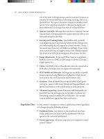
between key objects (Figure 2.43). The Specifi ed Steps setting allows
you to defi ne exactly how many blend steps Illustrator creates. Using
a higher number of steps results in a smoother transition, whereas a
lower number allows you to see the individual steps in the blend. The
Specifi ed Distance setting allows you to specify how far apart each step
appears from the next. When you want to create shading techniques
using blends, the Smooth Color option provides the best results. When
creating steps for a Flash animation, specifying fewer steps will help
playback performance.
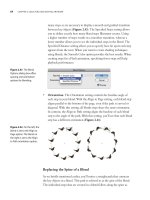
• Orientation. The Orientation setting controls the baseline angle of
each step in your blend. With the Align to Page setting, each blend step
aligns parallel to the bottom of the page, even if the path is curved or
diagonal. With this setting, all blends steps share the same orientation.
In contrast, the Align to Path setting aligns the baseline of each blend
step to the angle of the path. With this setting, you’ll see that each blend
step has a different orientation (Figure 2.44).
Replacing the Spine of a Blend
As we briefl y mentioned earlier, you’ll notice a straight path that connects
the key objects in a blend. This path is referred to as the spine of the blend.
The individual steps that are created in a blend follow along the spine as
Figure 2.43 The Blend
Options dialog box o ers
spacing and orientation
options for blending.
Figure 2.44 On the left, the
blend is set to the Align to
Page option. The blend on
the right is set to the Align
to Path orientation option.
CREATING TRANSITIONS WITH BLENDS
65
they connect the two outer objects. The spine is an editable path, and you
can use the Pen tool and the Direct Selection tool to edit the path if you
want to alter the direction of the blend steps. In fact, the position of the
control handles on a spine can control how the individual steps are distrib-
uted along the spine.
Additionally, you can perform a delicate operation—a spine transplant.
You can draw any vector path, open or closed, and use it as the spine for
an existing blend. To perform this surgery, select both the blend and the
path you’ve created, and then choose Object > Blend > Replace Spine.
Illustrator then uses the path you created as the spine for the blend,
allowing you to customize how blend steps appear.
Reversing Blends
With a blend selected, you can choose Object > Blend > Reverse Spine to
reverse the order of the key objects in your blend. This function is helpful
when you want to fl ip the blend so that it travels in the opposite direction.
You can reverse the stacking order of the key objects in a blend by select-
ing the blend and choosing Object > Blend > Reverse Front to Back. This
setting is especially useful for when you are using blends to create anima-
tions, which always travel in one direction. To have your animation play in
reverse, you use this feature.
Releasing and Expanding Blends
As with Envelope distortions, you can select an existing blend and choose
Object > Blend > Release, which removes the blend steps and returns
the artwork to its original state (just the two original objects). In addition,
you can choose Object > Blend > Expand, which applies the blend to the
artwork itself, leaving the individual blend steps visible and available for
editing. Once a blend has been expanded, it is no longer updated when the
original two objects are edited.
There is yet another way to release a blend that is useful, especially when
you’re creating frames for animations either that will be exported directly
from Illustrator as SWF (Flash) fi les or that will be imported into video
software such as Adobe After Effects, Adobe Premiere Pro, or Apple Final
Cut Pro. This method actually expands the blend into its individual steps
CHAPTER 2: SELECTING AND EDITING ARTWORK
66
and then places each step on its own layer. To release a blend in this way,
you must follow these steps:
1. If it isn’t already open, choose Window > Layers to open your Layers
panel.
2. In the Layers panel, highlight the blend object you want to release by
clicking it once (Figure 2.45).
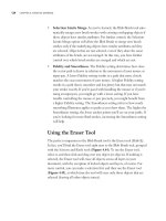
3. From the Layers panel menu (Figure 2.46), choose Release to Layers
(Sequence), or choose Release to Layers (Build).
You should use the Sequence option when you want each layer to contain
only one step, and you should use the Build option when you want to pro-
duce layers that add steps cumulatively to each layer that is created.
Figure 2.45 The Release
to Layers command is a
feature of the Layers panel,
so selecting the blend on
the artboard won’t help. You
have to highlight the blend
in the Layers panel.
Figure 2.46 Illustrator sup-
ports the ability to release
artwork to layers using the
Sequence or Build method.
Chapter
THREE
Technical Drawing
In our experience, we’ve found that some people seem to
“get” the concept of vector drawing immediately. Terms
such as anchor points, control handles, and compound paths
all make perfect sense to these folks, and the Pen tool
in Adobe Illustrator CS4 is a natural extension of their
imagination and creativity. They spend as much time in
Outline view as they do in Preview mode. These “people
of the path,” if you will, possess an analytical view, and
they can visualize the vector “building blocks” that make
up an overall graphic.
In this chapter, we’ll focus on the paths and anchor
points that make up a vector shape, and we’ll get a grasp
of all the tools you can use to create and modify these
paths. The good news is that Illustrator has plenty of tools and functions
that can help you create your masterpiece—or just a rectangle if that’s what
you need.
The artwork featured throughout this chapter comes from John Woodcock
(iStockPhoto; username: johnwoodcock).
67
CHAPTER 3: TECHNICAL DRAWING
68
DRAWING PRIMITIVE VECTOR
SHAPES
Illustrator contains a healthy set of primitive vector drawing tools. In this
case, primitive doesn’t mean “something simple” as much as it means “acting
as a basis from which something else is derived.” Artists are taught to sketch
using primitive shapes, such as rectangles and ovals, so that they can build
structure; you can certainly apply similar techniques to drawing with vector
shapes in Illustrator. Instead of trying to draw complex shapes, try to visual-
ize how you can combine simple shapes in a variety of ways to create more
complex ones (Figure 3.1).
Figure 3.1 Rather than draw com-
plex elements from scratch, you
can draw elements from a tree, for
example, from basic circles. You can
make the overall shape by adding
multiple circles to each other (left),
and you can create the detail by
subtracting circles from each
other (right).
The primitive drawing tools in Illustrator are split up between those that
create closed-path vector objects and those that create open-path vector
objects. Additionally, these tools are interactive in that you can specify or
control certain settings while drawing shapes. To take advantage of this
functionality, you choose a tool and begin drawing. As you hold down the
mouse button, you’re able to make changes to the shape you’re creating, but
once you release the mouse button, you commit to the shape. Let’s explore
how this works.
Using Closed-Path Shape Tools
The closed-path tools in Illustrator comprise the Rectangle, Rounded
Rectangle, Ellipse, Polygon, and Star tools, and they are all grouped
together in the Tools panel (Figure 3.2). To create any of these shapes,
choose the desired tool, click the artboard, and drag outward. While drag-
ging the pointer, you can add commands to adjust the shape interactively.
See Table 3.1 for a list of these interactive commands.
NOTE The Flare tool
that is used to create
vector-based lens are e ects
is also grouped with the
closed-path shape tools. A
valid question is why the Flare
tool is located here, but it’s
di cult to come up with an
acceptable answer. The Flare
tool is covered in detail in
Chapter 4, “Creative Drawing.”
DRAWING PRIMITIVE VECTOR SHAPES
69
Figure 3.2 The closed-path
shape tools are all grouped
with the Rectangle tool in
the Tools panel.
Table 3.1 Drawing with Closed-Path Shape Tools
Interactive
Command Rectangle Tool
Rounded
Rectangle Tool Ellipse Tool Polygon Tool Star Tool
Keyboard
Shortcut
M N/A L N/A N/A
Shift Constrains all sides
to be equal, resulting
in a perfect square.
Constrains all sides to
be equal, resulting in
a perfect square with
rounded corners.
Constrains all arc
segments to be
equal, resulting
in a perfect circle.
Constrains the
bottom side to
be parallel to the
constrain angle.
Constrains the
bottom two points
to be parallel to the
constrain angle.
Option (Alt) Draws the shape out
from its center point
instead of its corner.
Draws the shape out
from its center point
instead of its corner.
Draws the shape out
from its center point
instead of its corner.
N/A N/A
Command
(Ctrl)
N/A N/A N/A N/A Adjusts the inner
radius of the shape.
Spacebar Allows you to
reposition the
shape on the
artboard.
Allows you to
reposition the shape
on the artboard.
Allows you to
reposition the shape
on the artboard.
Allows you to
reposition the
shape on the
artboard.
Allows you to
reposition the shape
on the artboard.
Tilde Creates multiple
copies of the shape.
Creates multiple
copies of the shape.
Creates multiple
copies of the shape.
Creates multiple
copies of the shape.
Creates multiple
copies of the shape.
Up Arrow N/A Increases the corner
radius value.
N/A Increases the
number of sides.
Increases the number
of points.
Down Arrow N/A Decreases the corner
radius value.
N/A Decreases the
number of sides.
Decreases the
number of points.
Right Arrow N/A Turns on the rounded
corners.
N/A N/A N/A
Left Arrow N/A Turns o the rounded
corners.
N/A N/A N/A
Moving the
Mouse
N/A N/A N/A Moving the mouse
in a circular motion
rotates the shape.
Moving the mouse
in a circular motion
rotates the shape.
CHAPTER 3: TECHNICAL DRAWING
70
Using Open-Path Shape Tools
The open-path tools in Illustrator comprise the Line Segment, Arc, Spiral,
Rectangular Grid, and Polar Grid tools, and they are all grouped together
in the Tools panel (Figure 3.3). To create any of these shapes, choose
the desired tool, click the artboard, and drag outward. While dragging
the pointer, you can add commands to adjust the shape interactively. See
Table 3.2 for a list of these interactive commands.
Figure 3.3 The open-path
shape tools are all grouped
with the Line tool in the
Tools panel.
Interactive
Command
Line Segment
Tool Arc Tool Spiral Tool Rectangular Grid Tool Polar Grid Tool
Keyboard
Shortcut
\ (backslash) N/A N/A N/A N/A
Shift Constrains the
path to angles
in 45-degree
increments.
Constrains the X and
Y axes, creating a
perfect quarter circle.
Constrains the
path to angles
in 45-degree
increments.
Constrains the grid to a
perfect square.
Constrains the grid to
a perfect circle.
Option (Alt) N/A Draws the arc out
from its center point
instead of its corner.
Increases the
length of the path.
Draws the grid out from its
center instead of its corner.
Draws the grid
out from its center
instead of its corner.
Command
(Ctrl)
N/A N/A Adjusts the decay
of the path (making
the winds of the
spiral more drastic).
N/A N/A
Spacebar Allows you to
reposition the
path on the
artboard.
Allows you to
reposition the path
on the artboard.
Allows you to
reposition the path
on the artboard.
Allows you to reposition
the path on the artboard.
Allows you to
reposition the path
on the artboard.
Tilde Creates multiple
copies of the path.
Creates multiple
copies of the path.
Creates multiple
copies of the path.
Creates multiple copies of
the path.
Creates multiple
copies of the path.
Up Arrow N/A Increases the slope of
the curve to make it
more convex.
Increases the num-
ber of segments in
the spiral.
Increases the number of
rows in the grid.
Increases the number
of concentric dividers.
NOTE Even though
they are grouped with
the open-path tools, the Rect-
angular Grid and Polar Grid
tools create a combination of
both open and closed paths.
Table 3.2 Drawing with Open-Path Shape Tools
DRAWING PRIMITIVE VECTOR SHAPES
71
Interactive
Command
Line Segment
Tool Arc Tool Spiral Tool Rectangular Grid Tool Polar Grid Tool
Down Arrow N/A Decreases the slope
of the curve to make
it more concave.
Decreases the
number of
segments in the
spiral.
Decreases the number
of rows in the grid.
Decreases the number
of concentric dividers.
Right Arrow N/A N/A N/A Increases the number of
columns in the grid.
Increases the number
of radial dividers.
Left Arrow N/A N/A N/A Decreases the number of
columns in the grid.
Decreases the number
of radial dividers.
Moving the
Mouse
N/A N/A Moving the mouse
in a circular motion
rotates the path.
N/A N/A
C and X Keys N/A C draws the arc as a
closed shape instead
of an open path.
N/A C skews the columns in
the grid to the left;
X skews the columns in
the grid to the right.
C skews the
concentric dividers
toward the center;
X skews away from
the center.
F and V Keys N/A F ips the X and Y
axes of the path.
N/A F skews the rows in the
grid to the top; V skews
the rows in the grid to the
bottom.
F skews the radial
dividers toward the
left; V skews them to
the right.
Drawing by Numbers
If you’re an aspiring artist, you can buy a paint-by-number kit that uses
numbers to indicate where colors are supposed to go, taking the guesswork
out of the design process. Although being free to create is certainly a good
thing, you don’t want to be guessing when you’ve been asked to create a
shape that’s an exact size. The methods of drawing we’ve discussed to this
point are purely for those in a creative state of mind. As you create each
shape, your mind is saying, “Yeah, that’s about right.” However, sometimes
you are required to specify exact dimensions for shapes, and Illustrator can
be precise up to four decimal places.
To create any shape numerically, select the tool you need, click the artboard
once, and immediately release the mouse button. A dialog box appears,
letting you specify exact values for the shape or path you want to create
(Figure 3.4 on the next page). For most shapes, this action uses the point
where you clicked the artboard as the upper-left corner of the shape. To
draw a shape with its center point at the place you click, press the
Option (Alt) key while clicking, and then drag.
Table 3.2 Drawing with Open-Path Shape Tools (continued)
CHAPTER 3: TECHNICAL DRAWING
72
In Chapter 2, “Selecting and Editing Artwork,” we discussed how you can
use the Control panel or the Transform panel to change an existing object’s
dimensions numerically as well.
DRAWING AND EDITING FREE-FORM
VECTORS
Strip away the cool effects. Forget all the fancy tools. Ignore the endless
range of gradients and colors. Look past the veneer of both print and web
graphics. What you’re left with is the basis of all things vector—the anchor
point. You can learn to master every shape tool in Illustrator, but if you
don’t have the ability to create and edit individual anchor points, you’ll fi nd
it diffi cult to design freely.
Illustrator contains a range of tools that you can use to fi ne-tune paths and
edit anchor points. At fi rst, it might seem like these all perform the same
functions, but upon closer inspection, you’ll fi nd each has its use.
Mastering the Pen Tool
Just the mention of the Pen tool sends shivers down the spines of designers
throughout the world. Traditionally, the Illustrator Pen tool has frustrated
many users who have tried their hand at creating vector paths. In fact, when
the Pen tool was introduced in the fi rst version of Illustrator in 1987, word
had it that John Warnock, the brain and developer behind Illustrator, was
the only one who really knew how to use it. In truth, the Pen tool feels
more like an engineer’s tool than an artist’s tool.
But don’t let this prevent you from learning to use it.
Learning how to use the Pen tool reaps numerous rewards. Although the
Pen tool fi rst appeared in Illustrator, you’ll fi nd it in Adobe Photoshop CS4,
Adobe InDesign CS4, Adobe Flash CS4 Professional, Adobe Fireworks CS4,
Figure 3.4 Clicking a blank
area on an artboard or
the canvas with a shape
tool allows you to specify
numeric values and create
a shape precisely.
TIP When drawing
new paths with the
Pen tool, it’s best to set your
ll to None and your stroke to
black. Otherwise, Illustrator
will ll the path as you create
it, making it di cult to see
your work.
DRAWING AND EDITING FREEFORM VECTORS
73
and even Adobe After Effects CS4; if you know how to use it in Illustrator,
you can use it in all the other applications as well. You can use the Pen tool to
tweak any vector path to create the exact shape you need, at any time. Addi-
tionally, if you give yourself a chance, you’ll see that there’s a method to the
madness. After learning a few simple concepts, you’ll quickly realize that any-
one can use the Pen tool.
Usually, when new users select the Pen tool and try to draw with it, they
click and drag it the same way they might use a normal pen on paper. They
are surprised when a path does not appear onscreen; instead, several handles
appear. At this point, they click again and drag; now a path appears, but it
is totally not where they expect it to appear. This experience is sort of like
grabbing a hammer by its head and trying to drive a nail by whacking it
with the handle—it’s the right tool, but it’s being used in the wrong way.
While we’re discussing hammers, let’s consider their function in producing
string art. When you create a piece of string art, you fi rst start with a piece
of wood, and then you hammer nails part of the way into it, leaving each
nail sticking out a bit. Then you take colored thread and wrap it around the
exposed nail heads, thus creating your art. The design you create consists of
the strands of colored thread, but the thread is held and shaped by the nails.
In fact, you can say that the nails are like anchors for the threads.
When you’re using the Pen tool in Illustrator, imagine you’re hammering
those little nails into the wood. In this situation, you aren’t drawing the
shape itself; instead, you’re creating the anchors for the shape—the Bézier
anchor points. Illustrator draws the thread—the path—for you. If you think
about drawing in this way, using the Pen tool isn’t complicated at all. The
hard part is just fi guring out where you need to position the anchors to get
the shape you need. Learning to position the anchors correctly comes with
experience, but you can get started by learning how to draw simple shapes
(Figure 3.5).
TIP Holding the Shift
key while you click
with the Pen tool constrains
paths to 45-degree incre-
ments. Additionally, you can
choose View > Smart Guides
to have Illustrator display
helpful guides and hints as
you move the pointer (see
Chapter 1, “Creating and
Managing Documents,” for
more information about
smart guides).
Figure 3.5 Even though it
may appear complex at rst
glance, this skyline is made
up of of straight paths,
curved paths, and combina-
tion paths—which consist
of both straight lines and
curves.
CHAPTER 3: TECHNICAL DRAWING
74
Anatomy of a Vector Object
To truly comprehend how vectors work, you need a solid understanding of
the terminology. Otherwise, the words are meaningless and don’t make sense
when you try to apply techniques that use these terms. Overall, when working
in Illustrator, there are two parts of an object that you’re concerned with. The
vector path de nes the object in a mathematical way using anchor points. This
path doesn’t print. The appearance of a path determines how it will look when
printed and is de ned with attributes such as lls and strokes (Figure 3.6).
Figure 3.6 Vector graphics comprise of paths and appearances.
Drawing Objects with Straight Paths
Follow these steps to use the Pen tool to draw a straight path:
1. Select the Pen tool, and click the artboard once—do not click and drag.
Clicking once with the Pen tool creates a corner anchor point. This anchor
point is the start point of your path.
Appearance
Fill
Stroke
Path
Smooth Anchor Point
Control Handle
(aka Direction Handle)
Combination Point
(aka Change-Direction Point)
Corner Anchor Point
DRAWING AND EDITING FREEFORM VECTORS
75
2. Now, move your pointer to where you want the end point of your path
(Figure 3.7); click again to defi ne a second corner anchor point.
Figure 3.7 After you’ve
clicked once to create the
rst anchor point, move
your pointer to the location
where you want the second
anchor point.
Once you create this second point, Illustrator automatically connects the
two anchor points with a straight path, completing the line (Figure 3.8).
Figure 3.8 Clicking a
second time creates the
path between the two
anchor points.
For now, the fi rst concept becomes clear: When you’re using the Pen tool,
clicking—not dragging—is what defi nes a corner anchor point.
At this point, with your Pen tool still selected, Illustrator assumes you
want to add points to your path. By clicking again, you can create a
third corner anchor point, and if you do, Illustrator draws a path to
connect the second anchor point to the newly created one (Figure 3.9).
Figure 3.9 Each successive
click with the Pen tool con-
tinues to create additional
path segments.
Admittedly, this behavior may prove confusing because you may have been
expecting to start a new path rather than add to the existing one. To start a
new path, you fi rst have to deselect the current path.
CHAPTER 3: TECHNICAL DRAWING
76
Ending a Path
The easiest way to end a path is to click a blank area on the artboard while
pressing the Command (Ctrl) key, which temporarily changes your tool to
the Selection tool. Once you’ve deselected the path, you can click with the
Pen tool to start drawing a new path.
So, now you understand the second concept: When drawing an open path
with the Pen tool, each click adds another anchor point to the path until you
deselect the path, which is how you indicate to Illustrator you’ve fi nished
that path.
Drawing a Closed Path
You can indicate that you’ve fi nished drawing a path in another way—by
drawing a closed path. Until now, you’ve been creating open paths, but now
you can try to create a closed shape—in this case, a triangle, such as one that
might appear to draw the top of a building:
1. With nothing selected, select the Pen tool, and click once to defi ne the
fi rst anchor point of the triangle.
2. Move the pointer to another part of the artboard, and click again to
defi ne the second point.
3. Now move the pointer once more, and click to defi ne a third anchor
point (Figure 3.10).
A triangle has three sides, so you have all the anchor points you need,
but at the moment, the object you’ve drawn is an open path.
4. To complete the shape, move the pointer so it rests directly on the
fi rst anchor point that you defi ned, and click once to close the path
(Figure 3.11).
At this point, if you click again elsewhere on the artboard, the Pen tool
starts drawing a new path.
This brings you to the third concept: When you create a closed path, the next
click with the Pen tool starts a new path.
DRAWING AND EDITING FREEFORM VECTORS
77
Figure 3.10 A triangle
needs three anchor
points; the third click
creates two path
segments.
Figure 3.11 Clicking
the rst anchor point
completes the shape.
This is the shape after
it has been closed.
If this sounds confusing, try it once or twice, which should help—especially
if you pay attention to your Pen tool pointer. When you’re using the Pen
tool, the pointer changes as you draw, helping you understand the three
concepts you’ve just learned. When the Pen tool is going to start creating
a new path, a small x appears at the lower right of the icon; when the Pen
tool is going to add anchor points to an existing selected open path, no icon
appears next to it; and when the Pen tool is going to close a path, a small o
appears at the lower right of the icon (Figure 3.12).
Drawing Objects with Curved Paths
The paths you’ve drawn up until this point were all made up of corner
anchor points, which are connected with straight lines. Of course, you’ll
also need to create paths with curved lines, like those used to defi ne the
trees that appear in the skyline artwork; this section explains what you
need to know.
Figure 3.12 The Pen tool
subtly indicates which func-
tion it will perform.
NOTE By now, you
understand the state-
ment we made earlier about
how drawing the path is the
easy part of using the Pen
tool. The hard part is trying
to gure out where to place
the anchor points to get the
path you want.
Clicking starts
a new path.
Clicking removes an
anchor point from
an existing path.
Clicking adds a new
anchor point and a
segment to a path.
Clicking adds an
anchor point to an
existing path.
Clicking begins
editing a selected
open path.
Dragging changes
the direction
of the path.
Clicking closes
an existing path.
CHAPTER 3: TECHNICAL DRAWING
78
Curves are defi ned with direction handles that control how the paths between
anchor points are drawn. When you want to draw a curved path, you follow
the same basic concepts you learned for creating straight paths, with one
additional step that defi nes the direction handles.
1. To draw a curved path, select the Pen tool, and make sure an existing
path isn’t selected. Position your pointer where you want to begin your
path, and then click and drag outward before releasing the mouse but-
ton (Figure 3.13).
This action creates a smooth anchor point where you fi rst clicked and
defi nes direction handles at the point where you released the mouse.
2. Now position your pointer where you want the next anchor point to be,
and click and drag once again (Figure 3.14).
Using the direction handles as guidance, Illustrator draws a curved path
connecting the two smooth anchor points.
3. Move your pointer to another location on your artboard, and click and
drag to create a third smooth anchor point.
4. Click and drag the fi rst anchor point to close the path (Figure 3.15).
Figure 3.13 Clicking and
dragging with the Pen tool
de nes the smooth anchor
point and, at the same
time, lets you position the
direction handles.
Figure 3.14 Clicking and
dragging a second time
completes a curved path
segment between the rst
two anchor points and
de nes the next curve
that will be drawn.
DRAWING AND EDITING FREEFORM VECTORS
79
Figure 3.15 Clicking and
dragging the rst anchor
point completes the
curved shape.
We can now defi ne a fourth concept: Clicking and dragging with the Pen tool
creates a smooth anchor point and defi nes its direction handles.
Learning to anticipate how the placement of direction handles creates the
path you want takes time, but you don’t have to get it right the fi rst time.
Once you create a smooth anchor point, you can switch to the Direct
Selection tool and click and drag the anchor point to reposition it (Figure
3.16). Additionally, when you select a smooth anchor point at any time, the
direction handles become visible for that anchor point, and you can use the
Direct Selection tool to reposition those as well.
Figure 3.16 Using the
Direct Selection tool, you
can change the position
of anchor points and direc-
tion handles to adjust a
curved path.
Drawing Objects with Both Straight and Curved Paths
In the real-design world, shapes consist of both straight and curved lines.
You can use the knowledge you’ve gained up to this point to create paths
that contain a mixture of both corner and smooth anchor points. Basically,
you know that clicking with the Pen tool produces a corner anchor point
and a straight line, and you know that dragging with the Pen tool produces
a smooth anchor point and a curved line.
TIP Even the most
experienced Illustrator
artists need to switch to the
Direct Selection tool to tweak
the curves they create, which
can be time-consuming. To
get around this, you can press
the Command (Ctrl) key while
the Pen tool is active to
temporarily access the last-
used selection tool. While the
Selection tool is active, click
and drag the anchor points or
direction handles to adjust
the path, and then release the
key to continue creating more
points with the Pen tool.
CHAPTER 3: TECHNICAL DRAWING
80
Try drawing a path with both types of anchor points:
1. Select the Pen tool, and make sure you don’t have an existing path
selected (look for the small x icon on the Pen tool pointer). Click once
to create a corner anchor point.
2. Move your pointer, and click again to create a straight line (Figure 3.17).
3. Move your pointer, and click and drag to create a smooth anchor point.
You now have a single path that consists of both a straight line and a
curve (Figure 3.18).
You can use the Convert Anchor Point tool to convert a corner anchor point
to a smooth anchor point, and vice versa. To do so, choose the Convert
Anchor Point tool (which is grouped with the Pen tool), and apply the same
concepts you’ve learned. Click an existing anchor point once to convert it to
a corner anchor point, and then click and drag an existing anchor point to
pull out direction handles and convert it to a smooth anchor point.
Figure 3.17 You can begin
a new path by creating two
corner anchor points to
make a straight line.
Figure 3.18 Adding a
smooth anchor point
creates a single path with
both straight and curved
path segments.
DRAWING AND EDITING FREEFORM VECTORS
81
Changing Direction on a Path
As you were creating smooth anchor points, you may have noticed that
when you are creating or editing direction handles, a mirror effect occurs.
On a smooth anchor point, the direction points are always opposite each
other, and editing one seems to affect the other. Remember that the direc-
tion handles control how the path passes through the anchor point, so the
direction handles are always tangential to the curve (Figure 3.19).
Figure 3.19 With a smooth
anchor point, the direction
handles are always tangen-
tial to the curve of the path.
Creating a Combination Point
You can, however, change the direction of a path as it passes through
an anchor point:
1. Use the Direct Selection tool to select a smooth anchor point.
2. Switch to the Convert Anchor Point tool, and click and drag one
of the direction handles (not the anchor point).
In essence, this creates a combination point that you can then
continue to edit with the Direct Selection tool (Figure 3.20).
Figure 3.20 Clicking and
dragging a direction handle
with the Convert Anchor
Point tool creates a combi-
nation anchor point.
CHAPTER 3: TECHNICAL DRAWING
82
Creating a Combination Point as You Draw
To make life easier, you can create combination points as you draw with
the Pen tool:
1. Start by clicking and dragging to create a smooth anchor point.
2. Move your pointer to a different position, and click and drag again to
create another smooth anchor point and, hence, a curved path.
3. Now, position your pointer directly on the second anchor point you just
created. You’ll notice that the Pen tool icon shows a small inverted v in
its icon.
4. Click and drag the anchor point while holding the Option (Alt) key to
drag out a single direction handle (Figure 3.21).
5. Move your pointer to another location, and click again; you’ll see that
you’ve created a combination point.
Converting Type to Outlines
Overall, using the Pen tool takes some getting used to, and if you’re going
to use Illustrator often, it’s best to practice. One of the best ways to learn
is to reverse-engineer one that has already been created. You might fi nd it
useful to convert some type to outlines (select a type object and choose
Type > Create Outlines) to see how the anchor points are positioned in
those shapes. Try to re-create them on your own, and get a feel for when
you need a corner anchor point and when you need a smooth anchor point.
The more you use the Pen tool, the easier it will be to use.
Figure 3.21 As you’re draw-
ing a path with the Pen tool,
you can create a combina-
tion point by clicking and
dragging the last anchor
point of the path while
holding the Option (Alt) key.
DRAWING AND EDITING FREEFORM VECTORS
83
Adding and Deleting Anchor Points
Because anchor points are used to defi ne paths, you must add and delete
points from a path to achieve the shapes you need. You may think you can
select an anchor point with the Direct Selection tool and simply press the
Delete key on your keyboard, but doing this deletes a portion of the path
(Figure 3.22). Although this may be useful at times, what you really want
is to keep the path but remove the anchor point.
To delete an anchor point from a path without deleting the path, select the
Delete Anchor Point tool, and click the anchor point once that you want to
remove. Likewise, you can switch to the Add Anchor Point tool and click a
selected path anywhere to add a new anchor point to the path (Figure 3.23).
As an alternative, you can click the Remove Selected Anchor Points button
in the Control panel. Note that this button will not appear when all anchor
points of a path are selected.
Illustrator tries its best to help you get your work done, but sometimes its
overzealousness gets in the way. By default, when you move your pointer
over an existing path with the Pen tool, Illustrator, thinking you want to add
a point to the existing path, conveniently switches to the Add Anchor Point
tool. Likewise, when you move your pointer over an existing anchor point,
Illustrator switches to the Delete Anchor Point tool, thinking you want to
remove that anchor point. This is great, unless you wanted to start drawing
a new path with the Pen tool on top of an existing selected path. You can
turn this feature off by selecting the Disable Auto Add/Delete option in the
General panel in Preferences, which politely tells Illustrator, “Thanks, but
no thanks.”
Figure 3.22 Using the
Direct Selection tool to
select and delete an anchor
point (left) also deletes the
connecting path segments
(center). The Delete Anchor
Point tool keeps the path
closed but removes the
anchor point (right).
Figure 3.23 The Add
Anchor Point tool enables
you to add new anchor
points to an existing path.
CHAPTER 3: TECHNICAL DRAWING
84
Using the Reshape Tool
Using the Direct Selection tool to select individual points on a path results
in some anchor points moving while others remain stationary. In most
kinds of path editing, this is the desired behavior, although it can result in
paths that appear distorted. At times, you may want to stretch a path by
moving selected points, but you may also want other points to move as
necessary to maintain a nondistorted path appearance. The Reshape tool
(Figure 3.24) is perfect for this task.
1. Select a path using the Selection tool, and then select the Reshape tool.
2. Click an anchor point or part of a path that you want to act as a focus
point when you stretch the path. This way, you’ll have the most control
over how this focused point is moved.
You can also hold the Shift key and select additional focus points (as
well as drag to marquee-select additional anchor points).
3. Once you’ve selected your focus points, click and drag one of the focus
points to reshape the path.
You’ll notice that as the points that are in focus move, other points
in the path move as well to keep the general proportion of the path
(Figure 3.25).
The Reshape tool also comes in handy when you want to quickly turn a
straight path segment into a curved one. To do so, select the Reshape tool,
and click and drag any straight line segment (Figure 3.26).
Figure 3.24 The Reshape
tool is grouped with the
Scale tool in the Tools panel.
Figure 3.25 When some
anchor points on a path
are selected (left), dragging
with the Direct Selection
tool moves all the anchor
points as a single unit (cen-
ter). With the Reshape tool,
the selected anchor points
move in a proportionate
manner (right).
CREATING COMPOUND PATHS
85
Figure 3.26 The Reshape
tool lets you “pull out” a
curve from a straight line
segment.
Cutting Paths with the Scissors and
Knife Tools
When editing paths, you might fi nd you need to cut or split a path at a certain
point. With the Scissors tool selected, you can click any topmost vector path
(selected or not) to cut the path. In essence, you create two anchor points by
doing this. The Scissors tool can cut only one path at a time.
The Knife tool is much like the Scissors tool, but you cut or split a path by
dragging the pointer across a path instead of clicking it. Whereas using the
Scissors tool results in an open path, using the Knife tool results in at least
two closed paths. The Knife tool cuts through multiple paths when noth-
ing is selected but cuts through only objects that are selected (even if those
selected objects appear beneath other objects).
Using the Scissors or Knife tool is unwieldy at best, and you may fi nd that
if you’re doing a lot of path editing, you’ll get better results by using the
Pathfi nder functions or by using Live Paint groups (Live Paint groups are
covered in Chapter 4).
CREATING COMPOUND PATHS
A compound path is a single path that consists of more than one path. That
sounds like an oxymoron, no? Think of the letter o in the alphabet. It appears
to be a large circle with a smaller circle cut out from its center. How is such
a shape created with Illustrator? The answer is by drawing two circles and
combining them to become a single compound path. You do this by choos-
ing Object > Compound Path > Create. The result is a shape with a hole
cut out of the middle (Figure 3.27 on the next page). Compound paths are
treated as one entity, and therefore, both paths that make up this compound
path take on the attributes of the bottommost path. If your compound path
TIP If you nd you
need to cut through
multiple paths at once,
you should look into Rick
Johnson’s Hatchet tool that
is part of his Cutting Tools
plug-in (http://rj-gra x.com/
software/plugins.html).
TIP Holding the
Option (Alt) key while
dragging with the Knife tool
constrains the tool so that it
draws straight lines only.
NOTE You can also
use the Reshape tool
across multiple selected
paths.
CHAPTER 3: TECHNICAL DRAWING
86
consists of multiple shapes, Illustrator does its best to fi gure out which paths
become hollow and which appear solid.
Illustrator uses one of two methods to decide which paths of a compound
shape are hollow and which are solid. The default method is the Non-Zero
Winding Fill Rule method; Illustrator can also use another method, the
Even-Odd Fill Rule method. You’ll fi nd both of these buttons in the
Attributes panel, and you can click them when a compound path is selected
on the artboard. By default, Illustrator uses Non-Zero Winding Fill Rule
and makes the bottommost path clockwise and all the other selected paths
counterclockwise. For a detailed explanation of these rules, refer to the
sidebar “How Fill Rules Work.”
When you create a compound path and click Non-Zero Winding Fill Rule,
you can manually reverse the path direction to control whether a shape is
hollow or solid. Use the Direct Selection tool to select the path you need,
and click the appropriate button in the Attributes panel (Figure 3.28).
Figure 3.27 An example
of a compound path. The
outer shape of the eye
allows objects that appear
behind it (the yellow rays)
to be visible.
NOTE When a path
reverses direction in
a shape such as in a gure
eight, it can never be all
clockwise or counterclock-
wise. In such a case, the
direction of the region(s)
with the largest total area
is what de nes the result.
Figure 3.28 When using
the Non-Zero Winding Fill
Rule method for a com-
pound path, you can also
click Reverse Path Direction
On or Reverse Path Direction
O to control which parts of
a shape are solid or hollow.
Compound Path
Reverse Path Direction On
Reverse Path Direction O
Non-Zero Winding Fill Rule
Even-Odd Fill Rule
CREATING COMPOUND PATHS
87
How Fill Rules Work
More math! When you compare them to each other, Even-Odd Fill Rule seems more intuitive than the Non-Zero
Winding Fill Rule, and it is easier to predict which areas will be lled and which areas will be hollow. Although
you have more exibility with Non-Zero Winding Fill Rule—because you can manually control the result—this
rule is more di cult to understand, and the result is harder to predict.
With Even-Odd Fill Rule, every area inside an even number of enclosed areas becomes hollow, and every region
inside an odd number of enclosed areas becomes solid (Figure 3.29). An enclosed area refers to an area enclosed
by another path (or the loop of a path in a self-intersecting shape). The outermost enclosed area is always 1,
and therefore a regular path is lled (it is enclosed by a single area, which is an odd number).
1
1
2
2
3
2
1
1
2
3
Figure 3.29 When using the Even-Odd
Fill Rule method, Illustrator labels areas
using odd and even numbers to deter-
mine hollow and solid areas.
In contrast, the Non-Zero Winding Fill Rule method takes into account the direction of a path: An area
enclosed by a clockwise loop counts as +1, and an area enclosed by a counterclockwise loop counts as –1.
When the sum of these counts is zero, that area becomes hollow. When it is anything else, that area becomes
solid (Figure 3.30). Because you can manipulate the path direction to get di erent results from the same
shapes, Non-Zero Winding Fill Rule is more exible, but it’s an exercise of trial and error since you can’t see the
direction of a path on the artboard.
+1
-1
0
0
-1
0
+1
+1
0
-1
Figure 3.30 When using Non-Zero
Winding Fill Rule, Illustrator takes
into account the direction of the path
when it determines the hollow and solid
areas of a compound path. The arrows
indicate path direction.
Although the results in most cases are the same whether you use the Non-Zero Winding Fill Rule or Even-Odd
Fill Rule setting, sometimes the result is di erent (Figure 3.31).
1
2
1
2
1
2
1
2
Figure 3.31 Some compound paths
appear di erent, depending on the
ll rule speci ed, especially with self-
intersecting paths.
—Special thanks to Teri Pettit of the Adobe Illustrator team for helping explain these rules.
CHAPTER 3: TECHNICAL DRAWING
88
PERFORMING ADVANCED PATH
EDITING
Editing paths by hand can be tedious, but it doesn’t always have to be. Many
times, you’ll need to perform certain edits on vector paths, such as remov-
ing extra anchor points from a complex path or splitting larger shapes into
smaller ones of equal size. Other times, you may need to create outlines of
strokes, create duplicate paths at larger or smaller sizes, or simply clean up
loose paths and objects in your fi le. The good news is that Illustrator has a
variety of useful path functions you can use to perform these kinds of tasks.
You can fi nd the functions covered here in the Object > Path menu.
Working with the Join and Average
Commands
When you have two anchor points, you can use the Join command to con-
nect the two points with a straight path. Although this sounds simple, you
must meet certain requirements for the Join command to work:
• Only two anchor points can be selected. If you have three or more
anchor points selected, the Join command will not work (see next
bullet item for the one exception to this).
• If all the anchor points on an open path are selected, the Join command
draws a straight line between the start and end anchor points to close
the shape.
• The selected anchor points cannot belong to different groups.
• The selected anchor points cannot be part of a graph object.
If the two anchor points overlap each other exactly, Illustrator combines
the two anchor points and gives you the option of converting the resulting
single point to a smooth point or a corner point (Figure 3.32).
NOTE The Join com-
mand in Illustrator can
connect only two anchor
points at a time. If you need
to join multiple anchor points
or paths at once, you should
take a look at Rick Johnson’s
Concatenate plug-in
(http://rj-gra x.com/
software/plugins.html).
Figure 3.32 When you
are trying to join two over-
lapping anchor points,
Illustrator o ers you the
option of creating a corner
anchor point or a smooth
anchor point.