Essential Blender- P16 pps
Bạn đang xem bản rút gọn của tài liệu. Xem và tải ngay bản đầy đủ của tài liệu tại đây (1.58 MB, 30 trang )
1.00 and you'll see Suzanne's chin shrink to smaller than original size. Reset both the slider and
Min values to 0.00 for now.
Figure 8.12: The "Chin Big" shape key applied at -1.00.
With "Chin Big" still selected in the menu, LMB on the arrow to the right of the Max value. The
value changes to 2.00. Drag the slider to 2.00 and see Suzanne's chin grow much larger than you
originally intended. Reset the key value slider to 0.00 and the Max value to 1.00 for now.
Min and Max values can be useful to exaggerate or reverse shape keys for special effects. You
need to use them with care, however, as the results may not always be what you expect.
Animating Shape Keys
Before you begin animating, you should set the animation length by telling Blender how many
frames your animation will contain. Go to the Scene Buttons (F10). In the Anim panel, change
the "End" value to 100. The "Sta" (start) value should be 1. Your animation will begin on frame 1
and end on frame 100.
Start on frame 1 (Shift-Left Arrow). Select each of the four shape keys one by one from the pop-
up shapes menu (Nose Long, Nose Wide Long, Eyes Odd, Chin Big). LMB on the slider and
slide it to the right, away from zero. When you release the mouse button, the result will be
displayed in the 3D view. You may want to rotate the view a little with the MMB so you can see
what's happening. When you move the slider, the selected shape is used in proportion to the value
you set. If you slide the "Nose Long" slider to a value of 0.50, the nose will only extend half the
distance saved in the shape key.
If you move the slider for each shape key to a non-zero value, you will see that the mesh displays
the combination of all these shapes together. The ability to combine multiple shapes is one of the
strengths of Blender shape keys and means that it can sometimes be possible to create complex
animation with just a few shape keys.
Figure 8.13: All the shape keys set to 1.0.
It's important to note that each time you move a shape key slider, it sets a key frame on the
animation timeline. For this animation, you want Suzanne to start out looking normal, and then to
change shape before returning to normal at the end. So, you want all the sliders set to zero on the
first frame (frame 1). Select each shape key from the menu again and set each slider to zero.
Suzanne looks normal again.
First, we'll just mess with Suzanne's nose. Move forward thirty frames to frame 31 (Up Arrow
three times). Select "Nose Long" from the list and move the slider to 1.00. You'll see Suzanne's
nose stretch to full length. A key frame for this shape key has now been set at frame 31. Go back
to frame 1 (Shift + Left Arrow), move the mouse pointer over the 3D view and press Alt-A to
watch the animation. You'll see Suzanne's nose grow, then stay stretched until the frame counter
reaches frame 100. Then, the nose snaps back and re-grows as the animation replays from frame
1 again. Press the Esc-key to cancel the looping animation playback.
Now, move forward to frame 61 and LMB on the slider for the "Nose Long" key again. You don't
need to move it - just clicking on the slider sets a key frame and leaves the value at 1.00. Move
forward to frame 101 and move the slider back to 0.00. This will cause the nose to return to its
normal position by frame 101.
Move the mouse pointer over the 3D view again and press Alt-A to see the animation. Suzanne's
nose will grow, stay stretched for a while then shrink before replaying. Press the Esc-key to
cancel the playback.
What's happened?
By setting key frames, you've told Blender how the mesh should be deformed at those points in
the timeline. Blender automatically works out, or interpolates, the amount of deformation in
between those key frames. You can see the results by looking at the values displayed in the
sliders as you change frames. For example, if you move to frame 11, you will see that the slider
for "Nose Long" has a value of 0.24 on that frame. The value increases fairly steadily as it
approaches the first key frame at frame 31.
To get an even better look at what's happening, select a shape key from the shapes menu, position
the mouse cursor over the Buttons Window, then press Shift-Alt-A. Now the animation plays
while the sliders indicate the changing values of the selected shape key.
Note that shapes will constantly transform between key frames of different values so if you want
the mesh to hold a particular shape for a while before changing, you'll need to set a key at the
beginning and end of the block of time when you would like it to remain constant. That's why we
set a key frame value of 1.00 at frames 31 and 61: so the nose would stay stretched for a while
before shrinking again. In most cases you will find that you will set a key frame where you want
the shape to start deforming, another key frame where it will be fully deformed, a third key frame
where the shape begins to change back again, then a final key frame to indicate where the change
has finished.
Animating Multiple Shape Keys
If you have more than one shape key to animate, or if you want a visual reference for keeping
track of key frames, then the above approach becomes too awkward. To continue the tutorial,
open an Action Editor Window. You can change the existing Buttons Window into an Action
Editor Window via the Window Menu button (Refer to Chapter 2: The Blender Interface if you
need to look up how to do this).
In the Action Editor window (usually just called the Action Editor) you will see all of Suzanne's
shape keys listed. LMB on the small triangle next to the word "Sliders" to expose a key value
slider for each key. These sliders work in exactly the same way as those you used in the Shapes
panel, but now you can access them all at the same time without scrolling through a menu. A
marker is placed on the timeline for each key frame that is created. These markers can be
selected, moved, scaled and deleted in the Action Window (see the Character Animation chapter
for more on working within the Action Window).
Figure 8.14: The Action Editor window and Suzanne model before adding additional keyframes.
At this stage, you should already see a marker for each shape key on frame 1, and markers on
frames 31, 61 and 101 for the "Nose Long" shape key (press the Home-key to auto-zoom the
window to show all of the keyframes). The markers on frame 1 were set when you first clicked
each shape key slider and set the values to 0.00. The other markers show the key frames that were
set for Suzanne's stretching and shrinking nose.
The Action Window also indicates the current frame number with a vertical green line. LMB in
the Action Window and the indicator will move to the mouse cursor and set the current frame
accordingly
Morphing Suzanne
LMB on frame 31 in the Action Window to set the current frame to 31. You should see the green
vertical line that represents the current frame jump to that frame. Move the sliders for "Eyes Odd"
and "Chin Big" to 1.00. Blender sets markers on the timeline. Move forward to frame 61 either
by LMB on the timeline or by hitting Up Arrow three times. Move both sliders to 0.50. You can
LMB on the number on the slider to quickly type in an exact value if moving the slider isn't
accurate enough.
Move forward to frame 81 and set the slider values to 1.00 again. Then move to frame 101 and
set the sliders to 0.00. When the animation cycles you should see the nose grow and shrink as
before, but now the eyes and chin will grow, shrink a little, grow again then return to normal
before the animation replays. Press Alt-A over the 3D view to try it out. If you press Shift-Alt-A
with the mouse cursor over the Action Editor, you'll see the slider values change as the animation
runs.
Combined Shape Keys
When two different shape keys affect the same part of a mesh, Blender mixes the shapes together.
As with many things in Blender, the best way to understand this is to just mess with it, so let's do
that next.
Return to frame 31. LMB on the slider for "Nose Wide Long" to set it to a value of 0.00 on this
frame. This ensures the shape remains unchanged for the first 31 frames.
Now move to frame 61. Here you see Suzanne's nose fully stretched to the shape you made in
"Nose Long". If you remember, you also made "Nose Wide Long" from the "Nose Long" shape
but made the tip of the nose wider.
If you set the slider for "Nose Wide Long" to 1.00 on frame 61, you will see in the 3D window
that the nose grows even longer. In fact, it stretches twice as far as it was stretched when you
made that shape key. The reason is that the vertices of the nose have already moved once due to
the "Nose Long" shape key, and Blender moves them again for the "Nose Wide Long" shape key.
You can test this by setting the "Nose Long" slider back to 0.00 on frame 61 to see that the nose
returns to the shape you made for "Nose Wide Long". Leave it set to 0.00.
Now move to frame 101 and set the slider for "Nose Wide Long" to 0.00. Check the animation
with Alt-A.
Editing the Key Frames
The key frame markers in the Action Window can be edited in various ways. We won't go into
detail here, but you can play with them to get a feel for what they do. Pressing the A-key in the
Action Window selects or deselects all key frame markers. RMB clicking on a marker selects it,
and the B-key box select can be used to select multiple markers. You can also Shift-RMB to
select multiple markers. Pressing the G-key moves selected markers. Holding Ctrl to limits
movement to single frame increments. You can delete a selected key frame with X-key.
Basically, the key frame markers in the Action Editor can be dealt with just like normal objects in
the 3D view. If you find that your animation happens too quickly, or too slowly, you also have
the ability to scale the key frame markers. By selecting two markers (from the same shape key)
and pressing the S-key you can move them together or further apart.
Deselect all markers. Then, select the two markers on frame 61 for "Eyes Odd" and "Chin Big".
Press the X-key to delete these key frames. Now the eyes and chin will no longer shrink in the
middle of the animation. Play the animation to see the result.
There is much more you can do with shape keys: pinning shapes to view multiple shape keys at
the same time on different instances of the mesh, applying shape keys only to selected vertex
groups, and causing shape keys to animate based on the motion of other objects. These are
advanced subjects that you can investigate as you progress. Here is a quick overview of their
functionality.
With what you learned in this tutorial you know all you need to know to be able to make Suzanne
appear to talk. To do this you would need to make shape keys with the mouth in a few different
shapes, including wide open, fully closed and pursed into a tight "ooo" shape. You could even
import an audio track directly into Blender and, with practice, synchronize your key frames to it.
Figure 8.15: Some simple shape key suggestions for practicing basic lip-syncing with Suzanne.
Now that you are familiar with the Shape Keys work flow, see if you can make it happen!
Chapter 9: Blender Materials - Discussion
By Roland Hess
This is a practical primer on Blender's material and texturing system. Its goal is not to
comprehensively explain every option available to the user - the 2.3 guide and online references
will be good for that - but to provide a basic understanding so you can better grasp the tutorial in
this book, as well as online resources, and start branching out into your own work.
Figure MTD.01.0: The Material Buttons.
Managing Materials
Materials are created and linked to objects in the Links and Pipeline tab of the Material Buttons
(F5). The Material buttons will display the material for the active object in the 3D view. If there
is no material already linked to the active object, the Links and Pipeline tab will display a button
with the label "Add New". To its left is the activator for a drop down menu. At this point, you can
choose to either add a new material (Add New), or use the drop down to pick from the list of
existing materials. When you've added a new material (or chosen an existing one from the menu),
the Add New button changes into a text box that displays the material's name. It is a good idea to
use the text box to change the name to something that will help you remember what it is for,
should you revisit your project six months from now.
Figure MTD.01.1: The Links and Pipeline panel of the Material buttons, where you can add a
material or switch the active object's material.
Note: Blender does not come with a set of pre-built materials, but several community projects
have filled that gap - a quick Internet search will reveal a number of freely available Blender
material libraries.
Once a material is linked to an object, it is quite simple to change or remove that link. Changing
which material is linked to an object is just a matter of choosing a different material from the
drop down menu. To completely remove the link between a material and an object, click the "X"
button to the right of the material's name.
Material Preview
To the left of the Links and Pipeline tab (or above it, if you are working in a vertical buttons
window) is the Preview tab. The previews shown here are actual renders generated on-the-fly by
Blender's internal rendering engine, so they are highly accurate. The vertical row of buttons to the
right of the preview indicates which shape will be used by the renderer to make the preview, from
the standard cube and sphere to hair strands and the ever-popular monkey to represent more
complex objects. For an even higher quality preview, you can enable the "O" button below the
shape choices to use anti-aliasing in the previews.
Figure MTD.01.2: Material Preview.
Tip:
Material previews are generated by the internal renderer
and are very accurate.
Components of a Material
Blender materials each have four main components: base color, shaders, reflection/transparency
and textures.
Base color
Figure MTD.1: Color and Specularity buttons, and RGB sliders.
These controls set the basic color of the material. "Col" sets the overall color, while "Spe" and
"Mir" set the base colors for Specular highlights and Reflections. You can use the familiar RGB
sliders, choose to use Hue/Saturation/Value sliders with the HSV button, or LMB on the color
swatches at the left to pop up the graphical color picker.
Shaders
Figure MTD.2: The Shaders panel. The Diffuse and Specular shader selectors are here.
Blender's renderer has several options available for how exactly to shade the 3D geometry you've
created. The top set of controls is for Diffuse shading, which is the way that the renderer
calculates the general shading of the object. Here's a short breakdown of most of what is
available, and for what each might be best suited.
Lambert: Blender's default shading option. This is a good shading model for plastics and other
glossy, fairly smooth substances.
Minnaert: This shader allows you to affect the way that light plays on the portions of your
geometry that face the camera directly, as well as the portions that are perpendicular to it.
Varying the Dark slider and watching the Preview panel will quickly give you a feel for how it
reacts. This shader is useful for cloths, especially deep ones like velvet, and can also be used
(with Dark set carefully to lower values) for giving an ever present backlight effect to objects.
Oren-Nayer: A great general shading model for matte surfaces. Unless you are working with one
of the special cases mentioned in the other shader descriptions (cloth, plastic, etc.), try this.
Although it doesn't actually generate any texturing based on the "Roughness" value, it does
simulate the more diffuse scattering that such a surface would produce. As such, it works well as
a basis for human skin materials.
Toon: Toon shading breaks the shading into three flat regions - shadow, mid-tone and highlight,
and allows you to control the sharpness of the boundaries between them. Used correctly in
combination with the Toon specular shader and the edge rendering option, this can produce an
effect much like the standard three-part shading of the majority of today's hand-drawn animation.
Although each Diffuse shader has slightly different controls, they all have a Ref (Reflectance)
value. This represents the amount of light that reflects from the surface and reaches the camera. A
Ref value of 0.8 means that 80% of the light that reaches the surface from the scene's lamps is
used for shading purposes. It is up to you to determine how reactive your material will be to light,
but for most cases 0.8 is a good starting point.
The lower set of controls is for materials that have specular highlights. Specular highlighting is a
way of faking the reflectance of a light source itself on a surface. Don't go overboard with
specular highlighting - just because it's there doesn't mean you have to use it. Many times real
world materials that you are trying to simulate will appear more believable if you set the Spec
value to 0 or very near it. In general, the Spec value indicates the intensity of the highlight (using
the Spe color from the Material tab - remember that metallic objects should have highlights
colored near to their base color), while the Hard value controls the size of the highlight ("Harder"
substances like glass or diamond exhibit tiny, tight highlights, while softer substances like cloth
would have a larger highlight area).
The Blinn specular shader pairs well with the Oren-Nayer diffuse shader for most matte and
naturally occurring surfaces. Phong works well for glossy plastics. Phong and CookTorr seem to
produce good results for shiny metallics, as long as the Spe color is adjusted properly.
Reflection and Transparency
We just did reflectance in the Shaders tab, didn't we? Although named in a similar fashion, this is
different, and refers to actual visible reflections, like those most commonly seen on a mirror.
I
Figure MTD.3: The Mirror Transp tab, where reflection, transparency and refraction setting are
made.
The simplest way to create reflective surfaces in Blender is to enable the "Ray Mirror" option in
the Mirror Transp tab. Adjust the RayMir slider between 0 (no reflection) and 1 (all incoming
light is reflected, like a mirror). This method of creating reflections uses Blender's raytracer,
which is a way of following light rays from the camera back to their source. It creates great
effects, but can be costly in terms of render time. In order for "Ray Mirror" to work, you must
make sure that the "Ray" option is turned on in the Scene buttons (F10). If you want your
reflective objects to have an overall color cast (like the tinted reflection in red and green
Christmas balls), you will need to set the "Mir" (Mirror) color in the Material tab.
Figure MTD.4: The Ray option on the Render panel of the Scene buttons.
The other method of creating reflections is called Environment Mapping. It is not as accurate as
raytraced reflections, but has some advantages. You can find information about Environment
Mapping in the next section on Texturing.
Alpha and Opacity
The CG term for how much light passes through a surface is Alpha. Many people make the
mistake of initially conceptualizing Alpha as "transparency." The reason this is a problem is that
the Alpha scale runs from 0, which represents completely transparent, to 1, completely opaque.
So, when someone thinks about "increasing the amount of transparency", they think they should
make the Alpha value higher, when that is the exact opposite of what they should do. It's better to
think of Alpha as Opacity from the beginning, so the scale will always be intuitive. Higher Alpha
= higher opacity, while lower Alpha = lower opacity.
However you choose to think of it, the Alpha value slider is on the main Material tab with the
RGB color sliders. Changes to the Alpha slider, labeled "A", will be reflected immediately in the
Material preview. If you want to have the alpha visualized in the 3D view, you must then select
the object you wish to see (3D View Alpha is done on an object-by-object basis), switch to the
Object buttons (F7), then enable the "Transp" button on the Draw tab.
Figure MTD.4.1.tab: The Draw tab on the Object buttons.
Figure MTD.4.1.3d: The effects of enabling "Transp" in the 3D view.
As there are two ways to accomplish reflection, likewise there are two ways for Blender to render
Alpha. If you don't need to simulate refraction (the way that light bends when it passes through
materials of differing density, i.e. the lens effect), the best way to do it is to use something called
zTransparency.
Figure MTD.5: The Links and Pipeline tab where zTransp is located.
To use this very basic method, enable the "ZTransp" button on the Links and Pipeline tab of the
Material Buttons. Unless your visual demands are exacting (close ups of faces wearing glasses,
beauty shots of pouring water, etc.), ZTransp should serve most of your Alpha needs quite
efficiently.
If you need that last bit of refractive realism, though, you will need to use raytraced transparency.
To use this method, make sure that zTransp is disabled in the Material tab, then enable
"RayTransp" in the MirrorTransp tab. The IOR slider just below the RayTransp button controls
the Index of Refraction. You can find the Indices of Refraction for commonly occurring materials
like glass, water and different types of gems and stone quite easily on the Internet. Just be aware
that, as with Ray Mirror, using RayTransp can drastically slow your render times if used
indiscriminately. Always try zTransp first to see if it will be good enough for your purposes.
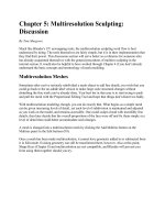
Figure MTD.6: Two objects rendered, the one of the left with ZTransp, the one on the right with
Ray Transp.
Before we move onto the fourth component of materials, Textures, you may have noticed that we
have ignored almost half of the controls on the tabs so far. There are a lot of special-purpose
items there that don't fit the scope of a "basics" text, but we'll highlight a few of them, just in case
you were looking for a way to achieve a specific effect.
Wire: toggle button on Links and Pipeline tab. Renders only the edges of the model, creating a
nice wireframe effect in renders.
OnlyCast: toggle button on Links and Pipeline tab. Causes faces linked to this material to not
appear during a render (making the object invisible), but to still cast shadows. This is a handy
trick for compositors and special effects, when a real-world object must cast a shadow within
your 3D creation.
Tralu: slider on Shaders tab. Translucency. Renders the faces of an object with light and shadows
as they strike the face from behind. While this will not produce the popular Subsurface Scattering
effect seen when you hold your fingers up to a bright light source, it can be used to enhance the
believability of thin organic materials.
Emit: slider on Shaders tab. This slider determines how much of an object is "self-lit". This will
neither cast light on objects, nor produce a glowing halo, but models that emit light in the real
world (like a light bulb) should have this value turned up to prevent them from being excessively
shaded by surrounding light sources.
Fresnel: two sliders on Mirror Transp tab, one each for Mirror and Transparency. The fresnel
slider can be used to enhance the realism of raytracing for certain materials. The fresnel value
controls how much of the raytracing effect is limited to portions of the object facing
perpendicular to the camera. Changes to these values display in the material preview, so you can
get a good idea of how they work just by playing around in the Material Buttons.
Textures
Up to this point, the material settings have allowed only a single color for each type of shading
(diffuse and specular). Almost nothing in the real world is completely uniform in color, and so
we turn to Textures to create the variations in color and other characteristics that occur across an
object's surface.
Figure MTD.7: A shape rendered with and without a zebra skin texture.
Textures are organized and layered in the Texture tab of the Material Buttons. Each of the buttons
in the stack represents a different channel for textures, so you can layer up to ten textures in a
single material.
Figure MTD.9: The Texture tab, with a stack of empty texture channels.
Each texture in Blender has three components: its actual content (e.g. computer-generated noise,
digital photo of a brick wall, etc.), how that content wraps around the geometry of the object, and
settings for which material properties (color, specularity, etc.) it affects.
Texture Management
Texture management is much the same as material management. To create a new texture, you
select one of the empty channels from the texture stack, then press the Add New button that
appears to the right of it. Different textures can be linked to the material by selecting a channel
and choosing an existing texture's name from the drop down menu. A texture can be unlinked
from a material by selecting its channel and clicking the Clear button.
Please note the check mark to the left of the default texture channel in the illustration.
Sometimes, you may want to prevent a particular texture channel from being rendered or
previewed, perhaps to isolate and tweak the look of a different channel. Turning the check mark
"off" by clicking it will cause the renderer to ignore that texture channel.
Texture Content
Textures come from two places: external images and Blender's internal texture generator.
For external images, Blender will let you use many formats, including Targa and PNG which
allow Alpha channels, and many video formats, depending on your system type (Mac, Windows
or Linux).
Although it's easier to get believable results with image textures, creating them can be time
consuming. To help with all the times you don't want to use an external image, Blender has a
powerful texture generation system.
When a new texture is created or selected in the Textures tab of the Material buttons, you can
access its texturing properties through the Texture buttons (F6). Although it is simple to switch
between the Material and Texture buttons (F5 to F6) in a single window, it is often useful to split
the buttons window, setting one window to Materials and the other to Textures.
Figure MTD.10: A custom Blender screen with Material and Texture buttons existing
simultaneously.
Create a new texture (or select an existing one) in the texture stack, then go to the Texture buttons
(F6).
Figure MTD.11: The Texture Type dropdown menu.
The Texture Type dropdown menu control contains all of the different kinds of textures,
including external images, that are available in Blender. Here is a brief rundown of some of the
more useful texture types and some suggested uses.
The majority of the textures are created by noise functions, which produce a random but
patterned variation throughout 3D space. Each of these noise-based textures has their own set of
controls, but most share some similar basics. The controls labeled NoiseSize, NoiseDepth and
Soft/Hard are common throughout. NoiseSize refers to the "zoom" level at which the texture is
used. Adjusting the NoiseSize slider and observing the Texture preview will quickly show you
how this functions.
The Soft/Hard settings control whether the noise moves softly from light to dark, or whether
there is a sharper transition
The other common control, NoiseDepth, is a little less obvious. NoiseDepth concerns how
detailed the texture will be. If it will only be seen from far away, NoiseDepth can stay at 1, as it
will only go "one level deep" when doing texture calculation. Higher values will add more detail
to the texture, which is perfect for close-ups, but at the cost of rendering time. The default value
of 2 seems to be a good general starting point, but people wanting to completely optimize their
render times should consider the level of texturing detail they will need.
Also, each of the noise-based textures can use one of several different methods for calculating
noise. The illustration shows you the default previews of each noise type for a quick reference.
Figure MTD.12: There are many noise types available for texturing.
On to the texture types:
Clouds: an excellent general purpose noise generator. Great for making texture layers for clouds
(of course), overall dirt and stains, and color variations over natural surfaces.
Marble: this texture type is good for any surface or material whose variation runs along parallel
veins.
Wood: a noise texture that is useful when you need noise patterns to appear in bands or rings, as
you would for cross sections of wood (surprise!), or concentric rings in a disturbed liquid surface.
Stucci: think Stucco. Apparently no one, not even Blender's shepherd Ton Roosendal, knows the
origin of the term. This is the texture type to use for creating small divots or peaks in surfaces
similar to the rough patterning found on finished stucco and gypsum walls. Almost all non-
metallic and non-glossy manufactured items (desktops, kids toys, interior car molding, your
computer monitor) can be simulated with a stucci texture.
Distorted Noise, Voronoi, Musgrave: these are more direct implementations of the different noise
models, where the mathematically or experimentally inclined can tweak obscure settings until
four o'clock in the morning.
Noise: this texture just creates dithered noise, which does not animate well. Use this only for
truly noisy things like static snow on an un-tuned television. Do not use this to add fine detail to
surfaces - it will result in an ugly "crawling" pattern during animation. Instead, use the stucci
texture for that sort of thing.
Those are the noise-based texture types. Targeted experimentation and the Texture preview tab
will be your best friends when using these tools. On to some of the non-noise based tools:
Blend: the blend texture (called "gradient" in some other applications) creates smooth value
transitions across the texture space. You have your choice of blend types: Lin, Quad and Ease are
all slightly different left-right blends, Flip XY creates a top-to-bottom blend, Diag runs from
corner to corner, Sphere and Halo make blends from a center point outward, and Radial spins the
blend around a central point like a clock arm or radar sweep.
Magic: if you choose the Magic texture, then start spinning through different depth value, you see
a series of seemingly unrelated color shifts. When layered together, these different color patterns
make excellent overlays for iridescent materials like oil slicks, insect bodies and different metals.
EnvMap
The last type of Blender-generated texture is the EnvMap, which was mentioned in the section on
material reflections. An EnvMap (Environment Map) is a special kind of image map that Blender
generates on-the-fly to simulate reflections. When an EnvMap is called for, Blender makes six
mini-renders of the scene from the standpoint of the object, stitches them together, then uses them
to fake a reflection from the object's location. It works very well, and can save valuable time
when working on an animation project.