Essential Blender- P18 ppsx
Bạn đang xem bản rút gọn của tài liệu. Xem và tải ngay bản đầy đủ của tài liệu tại đây (1.95 MB, 30 trang )
As a result, it is much easier to achieve a reflection using Raytrace, so that is the method you will
use here.
Note: Indiscriminate use of raytracing for reflections and transparency can still drastically raise
your render times. For rendering still images, this is not usually a big deal. For animation work,
where you might be rendering thousands of frames, those extra minutes can add up. If you will be
using reflection in your animation work, you are urged to investigate the Env Map method.
Reflective Materials Need Something to Reflect
Currently your scene has nothing to reflect, as only the desktop has been modeled. However, you
don't need to model an entire office around your desktop. You can simulate the reflected color
from the office walls by changing the world color to approximate the real environment.
! Select the World button (F8) and change the Horizon color.
Figure MTT.24: The World panel from the World buttons.
! Set the HoR to 0.540, HoG to 0.427, and HoB to 0.275
! Press ENTER to confirm those settings.
Adding the Power Supply for Some Close-Up Reflection
Apart from the walls and the world around the desktop, there is a power supply on the desk as
well. If you look closely at the reference photo at what appears to be shadow below the supply
and its cable, you will see that it is in fact a reflection on the desk surface and not really a
shadow.
If you are building your own power supply and cables for modeling practice, now would be a
good time to do so. If, however, you are using the included sample .blend file, then Shift-LMB on
the Layer 2 button on the 3D header to show the pre-made models.
Figure MTT.24.1: The objects on Layer 2 are now showing.
Set Raytrace Reflections for the Material
! Select the desktop object and move to the Material buttons (F5), selecting the Mirror
Transp panel.
This tab may appear complex, dealing with things like Fresnel, Falloff, and IOR, but for uses
where you only need simple reflection, there are only 2 settings and one button that need concern
you.
Figure MTT.25: Mirror Transp tab with raytrace reflection settings highlighted.
Ray Mir is the amount of raytraced reflections and varies between 0 and 1, with 0 reflecting 0%
of light from the surroundings and 1 reflecting 100% of it.
! Set it to 0.49
Depth refers the depths of calculation that Blender makes to trace the ray. For example, a ray that
must bounce off two different mirrors before hitting its light source would require two levels of
calculations. The default is 2 but its range is from 0 (no raytrace reflections) to 10 (significantly
longer but more accurate raytracing renders).
! Make sure it is set to 2.
! To enable the Ray Mirror material effect, turn on the Ray Mirror button.
Render the scene so far.
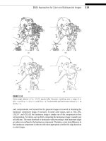
Figure MTT.26: A render with Ray reflection enabled. Note the subtle reflection, distorted by the
bump mapping on the desks surface.
Tip:
Raytraced reflections are enabled on the Mirror Transp tab.
If you don't see any reflection in your render, use F10 to enter the scene buttons and make sure
that the Ray button is turned On for the renderer.
Figure MTT.27: Enabling the Ray option in the Scene buttons.
The whole surface is looking much more realistic. However, real materials and surfaces will have
subtle details on them that will tell the eye whether or not what it sees is "real", or at least
believable.
Adding a History to a Material (Getting Dirty)
Close examination of a real desk surface shows polish and dust accumulation, as well as a few
knocks and marks here and there. If you can add these subtle hints to the material's history, you
can produce a much more believable material simulation.
A Material's History Can Be Broken Down Into 3 Possible Areas
Tip:
Adding dirt and irregular flaws will enhance a material's
believability.
Dirt
All real materials get dirty, either from accumulated dust or from interaction with liquids or
staining substances.
! Dust will collect in crevices.
! Dirt will transfer from mucky hands or dirty objects onto a surface over time.
Damage
Given time, any surface will sustain damage either through interaction with the atmosphere
(erosion/corrosion), or by being knocked or marked directly.
Deliberate Alteration
In this modern age, it seems that we can't leave a natural surface alone. Labels either stuck on or
sometimes embossed into a surface are commonplace.
Although the real desk surface in the reference is fairly clean, there is nothing to stop you from
adding a little dirt and damage. I sometimes enjoy a cup of coffee at my desk. While I typically
use a coaster to protect the desk's surface, let's pretend that I have in the past placed an overfilled
coffee cup on the desk's surface. The stain of a coffee cup is a unique shape and you therefore
can't use a procedural texture to imitate it. However, such a stain is very easy to produce and get
into Blender.
Figure MTT.28: A digital photo of coffee stained paper.
The image above was created by placing a coffee cup on paper, allowing it to dry, and then
placing the paper in a scanner. I touched up the picture in a paint program to give more contrast.
You could also take a digital photo of the paper, or, if your 2D digital painting skills are
developed enough, just paint the stain pattern directly in the image editor of your choice. For
your convenience, the image file for this stain has been included on the CD.
Image Textures
As with any decent 3D suite, you need a way of applying photographs, or graphic images created
in a paint package, to a material simulation. Blender is no exception and has some wonderful
tools that make the job easy.
There are 2 strategies for applying an image to a texture.
! Standard image mapping - where a picture is projected onto a surface from a single
direction, and;
! UV mapping - where a mesh is unwrapped to a flat surface upon which the image is
placed. This method allows precise control of how the image lays across the mesh model.
UV mapping is the preferred method of mapping for professional work, and you can learn about
Blender's incredibly simple and powerful UV mapper (see Chapter 10). For this example, though,
we will stick with the basics.
Mapping an Image to a Surface
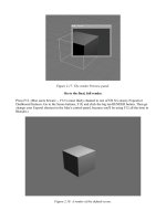
Standard image mapping can use one of four methods to project an image onto a surface.
Figure MTT.29: Blender's different image mapping methods.
! Flat - Projects the image along the Z axis of the object. The easiest way to think of this is
like a texture up or down onto a ground plane.
! Cube - Here the flat image is projected along each axis. Therefore a cube would receive
the same image on each of its six sides.
! Tube - As its name suggests, the image is projected around the Z axis of the object from a
central point. In other words the projector pans around the tube.
! Sphere - Here the image is projected from a central point in all directions.
There will inevitably be some distortion if the object is not a perfect plane, cube, tube or sphere.
Fortunately, we only need to map a simple image to a plane. You can therefore use Flat mapping
without having to worry about distortion. However, you also need to position and scale the coffee
cup mark so that it appears to occur "naturally". Let's start by adding a new texture to your
desktop material.
! With the desktop object selected press F6 to change to the Texture buttons.
! Select the next free available texture slot and select the Add New button.
! From the available Texture Type rollout select Image.
Figure MTT.30: The final Image that will be used for the texture.
This is the image you will use for the coffee stain.
It was created, as explained earlier, by scanning a real coffee stain on paper and adjusting the
contrast in a paint program. It was also converted to grayscale and inverted. You will use the Map
To panel to add color later.
! From the Image tab select Load Image and locate the coffee-stain1.jpg file.
I will explain the settings in a moment, but for now those shown are the defaults.
Figure MTT.31
Return to the Material buttons (F5) so that you can see how the image will be mapped to the desk
surface.
Orienting and Scaling an Image Texture to a Surface
Figure MTT.32
These are just the defaults, apart from setting the mixing mode to Add. In a moment I will
explain the mixing modes in detail, but for now the reason I have set it to Add is so that it will be
clearly seen on the desk surface.
! Press F12 to render the scene.
As you can see, the coffee stain has lightened the desk surface. It is far too big, though, unless
you are someone with a serious caffeine addiction. The image has been mapped to fill the whole
texture space of the mesh plane. For our purposes we need to change the size, or scale, of the
image and position it on the desktop in an appropriate place. You can change the scale and
position of an image texture by altering the sizeX, Y, Z and ofsX, Y, Z ("ofs" stands for "offset")
in the Map Input tab of the Material buttons.
There are several ways in which you can position and scale an image texture to a surface. You
will learn other methods later, but the one I show here will help further explain the Map Input
controls and their uses.
Map Input
Currently the image is mapped to fill the entire space of the mesh. This type of mapping is called
Orco(ORiginal COordinates) in Blender and is the default. As you can see from the Map Input
settings there are quite a few others available. Although you'll need to consult the Blender
documentation for a full explanation of all the settings, here are some of the more useful
attributes of the map input types:
! Glob(al): As its name suggests, the material will be scaled and oriented to the global co-
ordinates. This would mean that if the object moved in an animation the material would
remain in place, giving the illusion that the object was moving "through" the material.
! Object: With this type you can attach the material coordinates to another object such as an
Empty. The other object must be named and, of course, exist. This is incredibly useful, as
you can animate that other object to move, scale, and rotate, which causes the material to
do so as well.
! Orco: The default mapping method; uses the object's texture coordinates. If the object
moves, the material will move with it. In most circumstances this default works just fine.
It is possible to translate the Orco coordinates in scale and position.
! Win(dow): The texture is mapped as though being projected from the camera. Therefore
if the camera moves so does the texture.
There are other exotic mapping methods which, although useful, are not usually necessary for the
majority of texture needs.
Back to the Coffee Stain Texture
After playing around and using the preview render window, these are the settings that I found
work best for positioning the coffee stain:
Figure MTT.33: The final Map Input settings for the coffee texture.
Size
! Set sizeX, sizeY, and sizeZ to 6.20
Position (offset)
! Set ofsX to -2.300, ofxY to 1.200, ofsZ to 0.000
If you find it odd that the sizeX, Y and Z buttons make textures appear smaller as their values
increase, think of them as "how many times will the texture fit into the area" values. Therefore, a
number like 6.2 for the size values indicates that the actual texture image grows small enough
that 6.2 of them could fit within the texture coordinates.
If you render the scene now, you see a rather disappointing coffee stain that barely shows up,
only appearing in the wood grain. Why is that?
When you started creating the textures for your desktop you set some Warp and Stencil effects on
previous texture layers. These affect all textures below them. Although the Warp effect can be
turned off on a subsequent texture layer, Stencil cannot. This means to get an undistorted coffee
stain, it really should have been the first texture.
Reordering Textures
You may have wondered what those up and down arrows were in the Texture panel of the
Material buttons. These give you access to a temporary storage area called the buffer. You are
able to copy a selected texture to this buffer then paste it into another texture slot. All material
settings, like Map Input and Map To, are copied with the texture.
Figure MTT.34: The copy and paste buttons for texture channels.
To move a texture down one slot, you must first select it, choose the "Copy" button, select the
channel below it, and choose "Paste". Start by moving the coffee texture down several slots, then
proceed up through the stack, moving each entry down one level. Finish by making a copy of the
coffee texture and pasting it into the topmost Texture slot. You should end up with this:
Figure MTT.35: The Texture stack after shifting and duplicating.
You will notice that the Texture stack shows that there are now two copies of the coffee stain
texture in this material. Don't worry about that, as you can use the other copy for a nice special
effect in a bit. However, LMB the checkmark by the second coffee stain texture to temporally
turn it off while you set the Map To settings for the first.
Tip:
The copy and paste buttons are used to rearrange the
texture stack.
Setting the Map to Options for the First Coffee Stain Texture
With the first texture slot selected in the Material buttons, select the Map To panel so that you
can set the way this texture will be combined with the material color. The Mix blend mode will
mix both the black background of the image as well as the stain mark itself. You need to get rid
of the black background. Once again Blender has the ability to do this.
! Switch to the Texture buttons (F6) and in the Image tab select CalcAlpha and UseAlpha.
This will make the black area of the image transparent.
NOTE: Alpha (opacity), in materials, is quite complex, and even experienced users find
themselves trial-and-error toggling alpha related buttons from time to time to get things just right.
If things don't work exactly as you expect at first, don't lose hope!
! Switch back to the Material buttons. I am sure you don't need to be reminded of how to do
that. (HINT: F5. No more hints.)
! F12 to re-render.
Quite a subtle effect has now been produced. The stain has slightly bleached the surface, and
because the coffee contained far too much sugar, the specular and reflective difference between
the normal table and the stain can be seen.
You can now use the second copy of the coffee stain texture. The image texture itself is shared
between the two slots, but each instance here can have its own unique Map To settings.
! Set Col and Nor on to give you both color and a bump map effect.
! Change the blend mode to Subtract to give a darker color to the stain.
! Change the Col slider to around 0.50, so the new color isn't overpowering.
! And set the Nor value 2.00 to increase the bump size.
Figure MTT.36: The Map To settings for the second coffee stain channel.
A full render at this point will show that some of the wood grain has become darker, as though
coffee has spilled and dried in the crevices. However, it's a bit random. Why might that be?
Order of Textures and Their Effects on Each Other
Previously you set both a Stencil texture to mask some areas of following textures, and a Warp.
Once a Stencil is set, it applies to all following textures. A Warp, however, can be switched off
further down the stack.
! Select the texture slot immediately before the last coffee stain texture.
! Set Warp to "on" but make sure the fac(tor) amount is set to 0.00.
Figure MTT.37
These settings tell Blender that all following textures should have no Warp.
Figure MTT.38: The final render.
The desktop is now a reasonable simulation of the reference, with a few artistic interpretations
and additions, such as the coffee stain, on its surface.
Through thinking about and carefully observing materials in the real world, you have a
reasonable chance of using Blender's tool to make a believable approximation of those materials.
Combined with decent modeling and good lighting, working in this fashion can lead to
significantly more believability in your renders.
Chapter 10: UV Unwrapping and Painting:
Tools
By Roland Hess
Blender gives you an excellent and easy-to-use toolset for slicing and flattening mesh models in
order to make the application of 2D textures more detailed and efficient. Don't be confused:
"UV" unwrapping has nothing at all to do with "ultraviolet," the common expansion of the "UV"
acronym. It has to do instead with assigning a set of 2D coordinates to all vertices.
Don't they already have 3D coordinates? Yes. As you know, each vertex of a mesh already has an
X, Y, and Z coordinate. But if you make a copy of the mesh, slice it and flatten it out, each vertex
will also have another set of coordinates, ones more appropriate to a flat workspace. Normally,
you'd label the axes of a 2D space X and Y, but those are already taken. So, it's U and V. Where's
W? Don't ask.
Figure UVD.01: On the left, a mesh model in Face Select mode. On the right, that model
unwrapped in the UV Editor.
If you've never dealt with UV unwrapping and mapping before, we strongly urge you to work
through the tutorial section first in this chapter. Blender's UV Unwrapper is a highly interactive
feature, and one that can be best grasped by actually using it.
Unwrapping
The unwrapping process itself is found in Face Select mode, accessible on the 3D header's modes
menu.
Figure UVD.06: The Modes menu, with Face Select mode highlighted.
Most times, you will be unwrapping an entire mesh at once. In this case, simply using the A-key
to make sure that all faces are selected will be good enough.
The U-key brings up the Unwrap menu in the 3D view. It only works in Face Select mode.
There are a number of UV calculation methods, but only a few will be immediately useful.
The simplest ones to conceptualize are "Project from View" and the closely related "Project from
View (Bounds)." These options take the mesh exactly as seen in the current 3D view, and squash
it right into the UV Editor. (Technically, it's the "UV/Image Editor," but since we're only working
with UVs right now, we'll call it the UV Editor for short.)
Figure UVD.07: 3d view of sphere, flattened with project from view (bounds).
Figure UVD.08: 3d view of Suzanne, flattened with project from view (bounds).
Project from View can be good when you need to create a quick texture that corresponds closely
to the profile shape of the mesh.
Figure UVD.09: A fish texture, done with Project from View.
The only difference between the two is that "Project from View" creates UVs at roughly the size
that the mesh appeared in the 3D view, while "Project from View (Bounds)" fills the entire UV
space with the projection.
Some of the other options are also good for making quick unwraps on objects that will appear as
background items, or only for a short time. These are the Cylinder, Cube and Sphere options.
Each is good for unwrapping (surprise!) objects that closely match those primitives in shape.
There will be sections that don't map quite correctly or show distortion. If you're not sure if the
job they do will be good enough, give it a shot. You never now until you try.
Tip:
Meshes are unwrapped by entering Face Select mode and
using the Unwrap command from the U-key menu.
Other options aside, though, the most useful unwrapping method is simply called "Unwrap." It
uses a procedure called "Angle Based Flattening" in conjunction with seams marked in Edit
mode to give excellent results with very little effort.
Seams
In order for it to work properly, you must first tell the Angle Based Flattening unwrap tool where
to make cuts on the mesh. This is accomplished by adding seams to your model.
In Edit mode on a mesh model, seams are added by selecting edges, pressing Ctrl-E and choosing
"Mark Seam" from the Edge Specials menu that pops up. Marked seams appear as heavy orange
edges. A seam can be unmarked by selecting that edge, pressing Ctrl-E and choosing "Clear
Seam."
Figure UVD.02: The Ctrl-E Edge Specials menu for marking seams.
Although any selection method will work, it is often helpful when making seams to work in Edge
Select mode and to use Alt-RMB to select entire edge loops at once.
Seam placement is crucial. The best way to think about it is to visualize actually cutting slits into
your model so that, if it were made of paper, it would be able to lie flat on a desk.