SolidWorks 2010- P18 ppsx
Bạn đang xem bản rút gọn của tài liệu. Xem và tải ngay bản đầy đủ của tài liệu tại đây (566.54 KB, 30 trang )
Make Assembly Components Virtual
479
6. In the FeatureManager, the component will show that the virtual
component is a copy of the original part model. This is good since
you do not want to affect the original parts in any way.
NOte
It is not possible to make the parts of a subassembly virtual
while in the higher-level assembly. You have to open the subassembly sepa-
rately in order to make its components virtual.
7. After repeating the same step for the second component in the assem-
bly, click Save on the menu bar.
8. The Save Modified Documents window will display the assembly and
two parts that make up the assembly, as shown in Figure 14.8. Since
each component was modified, click Save All.
FIGURE 14.8 Save Modified Documents window
9. A second Save As window will ask whether the unsaved virtual com-
ponents are meant to be saved externally or internally, as shown in
Figure 14.9. Select the Save Internally option, and click OK. The
assembly with the internal virtual components is now ready to be
sent. The virtual components can then be saved externally on the
other end.
505434c14.indd 479 1/26/10 2:49:01 PM
Chapter 14 • Sharing Your Documents with Others
480
FIGURE 14.9 Save As window with option to save internally
NOte
After making all the components internal to the assembly, the
resulting file will be slightly larger than the sum of its individual files.
Create a Part from an Assembly
In the previous section, you made the components of the bulb subassembly
virtual in order to send the assembly as a single file. The two drawbacks to that
approach are the technique is not very useful for larger files, and the file size is
slightly larger than the sum of the individual components. But the advantage is
that the recipient of the file can make the components external once again and
have a standard assembly with its referenced components.
Another technique that is significantly easier and works just as well for large
assemblies as it does for small assemblies is creating a single part file from the
assembly. Saving an assembly as a part file creates a SolidWorks part file (*.sldprt)
that either contains solid bodies for each component or contains just the external
surfaces as surface bodies. The resulting file is much smaller in size compared to
the assembly and the parts.
When trying to decide whether this technique works for your needs, consider
how the resulting part is meant to be used. If the components are meant to be
used for manufacturing, then the solid bodies would need to be converted using
a utility such as FeatureWorks to recognize the features, if the feature data is
required. For large assemblies, this can be a painstaking process, and sending the
assembly and supporting components as native SolidWorks files would probably
be the best approach. However, if the feature data is not required, exporting the
files as either an IGES, STEP, or Parasolid is often requested by the machinist.
We have found that using this technique works best when the part is meant solely
for reference purposes or for creating renderings. We have even used this technique
when we had an assembly of a vendor-supplied part and we needed to use it only as
a portion of a larger assembly. By converting the parts of the assembly into solid
505434c14.indd 480 1/26/10 2:49:02 PM
Create a Part from an Assembly
481
bodies, the file size is smaller and requires less time for generation since there are
no features to load into memory. The resulting part file will also not have any ref-
erences to the original assembly or parts, and changes made will not update the
original files.
In this instance, assume that the resulting part will be used for quoting purposes.
You’ll create a single part from the top-level assembly, and each component will be
converted into a solid body, allowing the ability to hide and show individual compo-
nents. To do this, perform the following steps:
1. Open the desk lamp assembly that was created in Chapters 11 and 12.
2. Click the downward-pointing arrow next to the Save button on the
menu bar, and select Save As.
3. In the Save As Type field, select Part (*.prt, *.sldprt).
Below the Save As Type field, you are presented with three options.
Each option affects how the part will be created from the assembly.
External Faces Selecting External Faces will create a part file with
no solid bodies and only the outside visible faces as surface bodies.
Exterior Components This option will create a part file with the
visible components saved as solid bodies. Any internal components
that are not visible will not be saved.
All Components This option will convert each individual compo-
nent in the assembly into a solid body.
4. Select the All Components option, and click Save to create the new
part file. The assembly can now be closed, and just so you can see the
result, you will open the new part file.
5. Click Open in the menu bar, select the part file you just created, and
click Open.
6. If prompted to proceed with feature recognition, click No.
7. The FeatureManager, instead of displaying parts and assemblies, now
has a list of solid bodies, as shown in Figure 14.10. Each solid body
corresponds to a component in the assembly, giving the recipient the
ability to view each component individually.
505434c14.indd 481 1/26/10 2:49:02 PM
Chapter 14 • Sharing Your Documents with Others
482
FIGURE 14.10 Components in part file converted to solid bodies
Open Files in eDrawings
Earlier in this chapter we briefly covered how eDrawings can be used as a viewer to
open native SolidWorks files as well as documents saved in the eDrawings format.
Before moving on to the next chapter, we’ll talk about the eDrawings software.
Instead of going into great detail, we will show you how to open a document in
eDrawings:
1. Locate SolidWorks eDrawings 2010 in your program group, and
launch the program, as shown in Figure 14.11.
FIGURE 14.11 eDrawings program
505434c14.indd 482 1/26/10 2:49:06 PM
Open Files in eDrawings
483
2. Select Open on the toolbar in the eDrawings window.
3. At the bottom of the Open window, you can select the file format of
the file that you intend on opening, as shown in Figure 14.12. Select
eDrawings Files (*.edrw).
FIGURE 14.12 Selecting the eDrawings file type
4. Browse to the folder that contains the Base,Lamp.edrw file created
earlier, select the file, and click Open.
5. The graphics area of the eDrawings software will now display the draw-
ing. You will notice that it looks exactly like the drawing in SolidWorks.
In fact, it is the same. The only difference is that you cannot make any
changes to the drawing.
6. The user interface for eDrawings also a lot simpler from that of
SolidWorks. As you can see in Figure 14.13, the tools available can be used
for rotating, zooming, and measuring. That is why the program is perfect
for non-SolidWorks users; it is an easy program for anybody to use.
FIGURE 14.13 eDrawings toolbars
7. After you are finished exploring eDrawings, close the program.
505434c14.indd 483 1/26/10 2:49:09 PM
Chapter 14 • Sharing Your Documents with Others
484
If You Want More Practice…
Throughout the chapter we introduced you to a couple of ways to save files to
make it easier to send them via email. Now would be a good time to experiment
with other SolidWorks files using some of the other export formats listed in the
file type field of the Save As window. Many of the file formats have their own set
of options. To learn more about the options, you can click the Help button in
the lower-right corner of the Export Options window.
Are You Experienced?
Now You Can…
Save a document as a PDF file
Create a detached drawing
Use the Pack and Go utility
Save a document in the eDrawings format
Save components of an assembly as virtual components
Save an assembly as a part file
505434c14.indd 484 1/26/10 2:49:09 PM
Chapter 15
Creating Your Own
Templates: Part 1
Create Part and Assembly Templates
Create a Title Block for Parts and Assemblies
Create a Custom Property Tab
505434c15.indd 485 1/26/10 2:49:15 PM
Chapter 15 • Creating Your Own Templates: Part 1
486
S
olidWorks comes preinstalled with templates for drawings, parts, and assem-
blies as well as sheet formats for the most common drawing sheet sizes.
These templates are enough to get you started when using SolidWorks, but as
you become more familiar with the software, you may find yourself making
changes to these templates every time you create a new document. Many companies
use these templates as the starting point when creating their own standard tem-
plates, and that is exactly what you will be doing in this chapter and the next one.
Starting with the out-of-box templates that ship with SolidWorks, you will
be creating a whole slew of custom templates that can be used throughout this
book. In this chapter, you will be concentrating on parts and assemblies as well
as some additional items that can be used in the two environments. Usually it
is the duty of the CAD manager or one of the power users in an organization to
create the templates that will be used, but there may be a time when that power
user is you. With the skills you will learn in these two chapters, you will be able
to create the most commonly used templates in SolidWorks.
Create Part and Assembly Templates
In the previous chapters, when it came time to create a new part or assembly,
you were instructed to download the appropriate templates from the companion
website. In the next couple of sections, you will be re-creating those templates
starting with the preinstalled templates. Creating custom templates of parts and
assemblies allows you to set document properties, custom properties, and other
modifications for each only once.
Few organizations need to create more than one part and assembly template to
be used for all modeling. But we have found that it is sometimes helpful to have
multiple templates to match different part and assembly types. For instance, if
your organization commonly creates models in both English and metric units,
you can create separate templates for each unit type.
Create a New Part Template
The part template that comes installed with a fresh copy of SolidWorks will work
for many users without any modifications. When creating the templates that ship
with the software, SolidWorks did a great job of determining the combination
of common document properties that works for most users. However, we have
always found the need to make small changes, such as the number of decimal
505434c15.indd 486 1/26/10 2:49:15 PM
Create Part and Assembly Templates
487
places on dimensions, the default display settings, and even what document prop-
erties are included by default. Custom templates can then be shared throughout
your entire organization.
Making refinements to the SolidWorks templates is not only a huge time-saver
in the grand scheme of things, but it is also extremely easy. Since you will be
starting with the standard templates available, you will only need to make a cou-
ple of small modifications. The following steps will take you through the process
of making the small changes that are required for the examples in this book:
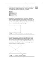
1. Click New in the menu bar.
2. If the New SolidWorks Document window is displayed in the simplified
mode that displays the three basic templates for parts, drawing, and
assemblies only, click the Advanced button in the lower-left corner of
the window, as shown in Figure 15.1.
FIGURE 15.1 New SolidWorks Document default novice view
3. In the New SolidWorks Documents window, select the Part template,
and click OK.
Access the Document Properties
Document properties are properties that affect the active document only. Many times
there a few properties that need to be adjusted to meet your needs, and instead of
remembering to do so each time you create a new part model, you can do it once in
the template. All future parts created from the template will contain the properties
O
SolidWorks will save
your preference so
that each time you
create a new docu-
ment, the Advanced
view will be the
default view.
505434c15.indd 487 1/26/10 2:49:17 PM
Chapter 15 • Creating Your Own Templates: Part 1
488
specified in the template. In this section, you will make some minor changes that will
affect how you create the parts in this book.
NOte
Modifications made to a template will affect only future parts.
Existing part models will not be updated at the same time.
1. In the menu bar, click the Options button.
2. On the top of the Options window, there are two tabs. The first tab,
System Options, is where you can specify settings that will affect
the entire SolidWorks environment regardless of which file is cur-
rently open. The second tab, Document Properties, is used to specify
options in the currently active document only. Select the Document
Properties tab to view the categories for the settings available for the
current document type.
3. Since the current document is a part, the section on the left of the
Document Properties window displays the option categories that apply
to part documents, as shown in Figure 15.2. To view the options for
each category, select the category, and the options will be displayed to
the right of the section.
FIGURE 15.2 Document properties category list
Explore the Option Categories for Parts
Although the sections on the Document Properties tab are available in parts, assem-
blies, and drawings, the options available in each section relate directly to the active
505434c15.indd 488 1/26/10 2:49:19 PM
Create Part and Assembly Templates
489
document. As you become more comfortable with working in SolidWorks, you may
encounter the need to make fine adjustments in your document. Sometimes it could
be as basic as adjusting the units in the document, but there are many more adjust-
ments that can be made. The best way to learn about each option is to click the Help
button in the lower-left corner of the window, and the description of each option in
the window will be described in the Help window. Although the help file is a good
start, the best way to learn is to play. We recommend opening a new document and
experimenting with different settings so you can get a good feel for what can be
done. The following are the main categories on the Document Properties tab along
with a brief description of each:
Drafting Standard Use this option to select a drafting standard for detailing in
the active part file, as well as to rename, copy, delete, export, or load saved cus-
tom standards.
Detailing This property contains options related to how annotations are han-
dled in the active document including text size, importing of annotations, and
the cosmetic thread display.
Grid/Snap This property contains options on the grid display in the active
document as well as the snap functionality.
Units The Units options are used to specify the unit system used such as IPS
and metric. You can also adjust the precision of dimensions, mass properties,
and simulations.
Colors In part models, you can adjust the colors for each feature type. For
other color adjustments such as for the background, text, planes, and others,
you should use the system colors. Sometimes it is nice to customize the colors,
but if you send the file to another user, the difference may become confusing.
Material Properties You can adjust the density of the material specified for the
active part as well as how the section for the material is displayed.
Image Quality You can adjust the display quality for the active part. You
can also make further adjustments in the Performance section of the System
Options section.
Plane Display You can adjust options such as the color, transparency, and
intersection of planes.
DimXpert You can specify the default settings affecting how annotations are
added to a part using DimXpert.
505434c15.indd 489 1/26/10 2:49:19 PM
Chapter 15 • Creating Your Own Templates: Part 1
490
NOte
DimXpert allows you to fully annotate a part model, satisfying
the requirements of ASME Y14.42-2002, which eliminates the need to have
separate part drawings.
Specify Options for the Part Template
The following options are the most common adjustments we usually need to
make to a part file. To save time, we often make these adjustments at the tem-
plate level so all our parts will be created correctly. These options are also the
ones used when you created the parts and assemblies in earlier chapters. To set
the document options for the template, do the following:
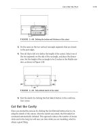
1. In the category list, select Units to specify the units used for dimen-
sions, Mass Properties, and Motion Studies.
2. Ensure that the IPS unit system is selected in the Unit System sec-
tion, as shown in Figure 15.3.
FIGURE 15.3 IPS unit system specified in the document properties
3. Below the Unit System section is a table that lists the type of units
in the document that can be updated. For the Length row, select the
downward-pointing arrow to view the number of decimals that can
be specified when adding dimensions to the part model, as shown in
Figure 15.4. Select the entry that shows .123; this entry will specify
that dimensions in the part model and sketches will be displayed with
three places after the decimal point. If you require more precision,
you may specify that dimensions are displayed with up to eight num-
bers after the decimal points.
After changing the number of digits that will be displayed in dimen-
sions in the table, a bubble will display a message alerting you that
since the current standard has been modified, the standard name will
be changed to “ANSI-MODIFIED.” At this point, you will continue
making changes to the settings.
505434c15.indd 490 1/26/10 2:49:21 PM
Create Part and Assembly Templates
491
FIGURE 15.4 Specifying the precision of length dimensions
4. Select Image Quality in the options tree.
5. At the top of the Shaded And Draft Quality HLR/HLV Resolution sec-
tion, you can use the slider to set the image quality resolution of the
part in the graphics area, as shown in Figure 15.5. By default, the slider
position is in the middle of the bar. As you move the slider to the left
toward the Low end, the quality of the model is of lower quality, but it
does speed things up. By moving the slider toward the High end, the
quality increases, but it can make some older systems run painfully
slow. Move the slider to the ¾ position on the High end of the bar.
FIGURE 15.5 Adjusting the display resolution of the active part
Save the Modified Document Settings
Even though you made only a couple of adjustments to the document proper-
ties, it wouldn’t hurt to save these changes for future documents. Not only will it
come in handy when creating other templates that are meant to share the same
options, but you can use the saved changes to update the properties of existing
documents. Once a modified standard is saved, it can be recalled in another doc-
505434c15.indd 491 1/26/10 2:49:24 PM
Chapter 15 • Creating Your Own Templates: Part 1
492
ument, and the options will be applied. The following steps will save the settings
that you will then use to create your assembly template with the same options.
NOte
You can also store standards files on a network location, giv-
ing other users in your organization the ability to update any files they may
have to the current company standards.
1. In the option tree at the very top of the list, select Drafting Standard.
2. Click Save To External File.
3. In the Save As window, browse to a folder that you want to be used for
storing data from SolidWorks.
4. Specify the name that you want to save the modified standard as in the
File Name field, or accept the default name
ANSI-MODIFIED.sldstd.
Click Save to save the standard and to close the Save As window.
Save the New Part Template
Before you can use a new template for creating parts, you must save it in the
appropriate templates folder. As soon as it is saved, it will become available in
the New SolidWorks Documents window. If the template is saved in a shared
network location, all SolidWorks installations that point to the template folder
will also be able to use the template. Save the template as described:
1. Click OK in the lower-right corner of the Document Properties win-
dow to save the changes made to the part template.
2. Once all the options have been set per the previous sections, click
Save in the menu bar.
3. In the Save As window, browse to the location where your SolidWorks
templates are located. In most cases, the location for templates in
SolidWorks 2010 is
C:\ProgramData\SolidWorks\SolidWorks2010\
templates
.
NOte
If you are not sure which folder SolidWorks is using for its templates,
you can nd out in System Options
➢
File Locations
➢
Document Templates.
4. Click the Save As Type field, select Part Templates (*.prtdot) from the
list, and change the File Name to NER Part to prevent overwriting
your existing template. Click Save to the part template.
505434c15.indd 492 1/26/10 2:49:24 PM
Create Part and Assembly Templates
493
NOte
If you downloaded the part template in previous chapters, you
can just overwrite the version downloaded or choose to skip saving the
changes you made.
5. Close the part template, and it will be ready for use the next time you
need to create a part file.
Create a New Assembly Template
with Saved Standards
In the previous section, you created a new part template from a preinstalled tem-
plate. You made adjustments to the document properties to better suit your needs,
but that leaves the assembly template that you still need to create. Instead of fol-
lowing the same steps to create a new assembly template, you can use the modified
standard template you previously saved. Since the document properties you speci-
fied in the part template correspond exactly with those you need to adjust in the
assembly template, there will be no issue with importing the same options. The
following steps will describe the process of importing settings previously saved.
NOte
Not all document properties are available in all three SolidWorks
le formats. There may still be additional adjustments that cannot be shared
among the different formats. If you’re not sure what has been imported, it is
always a good idea to check how the options were applied.
1. Click New in the menu bar, and select the Assembly template in
the New SolidWorks Document window. Click OK to open the new
assembly file.
2. If prompted to begin the new assembly by inserting parts in the file,
click the red X in the Begin Assembly PropertyManager.
3. Select the Options button in the PropertyManager, and select the
Document Properties tab in the window.
4. In the Drafting Standards section, click the Load From External File
button.
5. Browse to the folder in the Open window that contains the standards
file you saved in the previous section. Select the file, and click Open.
6. Since all the document properties were already specified in the saved
standards, all that is left to do is click OK to save the changes and
close the Document Properties window.
505434c15.indd 493 1/26/10 2:49:24 PM
Chapter 15 • Creating Your Own Templates: Part 1
494
7. Click Save in the menu bar, and browse to the folder that contains
the templates that SolidWorks uses.
8. Change the file type in the Save As window to Assembly Templates
(*.asmdot), and change the filename to NER Assembly. Click Save to
save the new template. After saving the template, it is safe to close the
file since there are no other options you need to set at this time.
Create a Title Block for Parts
and Assemblies
In SolidWorks 2007, the ability to annotate a part or assembly was introduced.
The addition of the DimXpert command gave the ability to add notes, dimensions,
and even geometric tolerancing to the actual 3D model. Then in SolidWorks 2009,
a bill of materials table was introduced to the 3D environment. Over the years,
SolidWorks has made these enhancements to satisfy the requirements of ASME
Y14.41-2003, Digital Product Definition Data Practices.
The Digital Product Definition Data Practices standard specifies how drawings
can be eliminated by fully annotating a 3D model. In lieu of a 2D drawing, the
design intent can be properly described to all viewing parties with a fully dimen-
sioned part and any other manufacturing, documentation, or quality informa-
tion. But there was always one bit of critical information that was very difficult
to present to the recipient of the part — the information that would normally be
delineated in the drawing title block. This information could always be included
in notes in the model or even a separate document, but nothing beats the sim-
plicity of a drawing title block.
Luckily, in SolidWorks 2010, the ability to add a title block to the 3D environ-
ment was finally introduced. You can insert a 2D title block table in a part or
assembly that can mimic that of a drawing. No matter in what direction a 3D
model is being viewed, the title block and its text will always remain normal to
the viewing plane. Just like a title block in a drawing, you can link text to docu-
ment or custom properties and have the text dynamically updated as the proper-
ties are updated.
You can create a title block for 3D components from scratch by modifying
a table that resembles a spreadsheet. By adding rows and columns, merging
cells, and adding text, you can create a floating title block that may look almost
exactly like the one on your 2D drawings. Also, SolidWorks has a standard tem-
plate that matches the title block in the standard drawing template. Since you
will be creating your drawing template from the standard template, you can do
the same with the title block template.
505434c15.indd 494 1/26/10 2:49:24 PM
Create a Title Block for Parts and Assemblies
495
Insert a Title Block into a Model
Whether you are inserting the standard title block template or your own title block
that matches your organization’s layout, the process is the same. You launch the
Title Block Table command; a title block is then placed directly into the graphics
area of a part or assembly. You can then move the inserted title block anywhere in
the 2D plane that is normal to the viewing plane. The following will describe the
process for inserting a title block into a model.
1. Click New in the menu bar, and select the NER Part template you cre-
ated earlier. Click OK to open the part.
2. In the menu bar, select Insert
➢ Tables ➢ Title Block Table, as shown
in Figure 15.6.
FIGURE 15.6 Title Block Table tool in menu
3. Click the Browse For Template button in the Title Block Table
PropertyManager, as shown in Figure 15.7.
FIGURE 15.7 Opening the template for the title block table
O
A title block cre-
ated for parts and
assemblies cannot
be inserted into a
drawing.
505434c15.indd 495 1/26/10 2:49:28 PM
Chapter 15 • Creating Your Own Templates: Part 1
496
4. Browse to the folder that contains your title block templates. By
default the location should be
C:\Program Files\SolidWorks Corp\
SolidWorks\lang\english
. Select the file named
Title Block.sldtbt, and click Open.
tIp
You can determine the folder path for your title block templates
by referring to the Title Block Table Template path displayed in the File
Locations tab of the System Options window.
5. Click the green check mark in the Title Block Table PropertyManager
to insert a generic title block into the part file.
6. As you move the mouse pointer in the graphics area, the title block
table will move with the pointer. Click and release the left mouse but-
ton to place the title block in the part. Once inserted into the part
model, as shown in Figure 15.8, you can begin to make your required
modifications.
FIGURE 15.8 Unmodified title block table
Edit Static Text in the Title Block
The title block table that is included with SolidWorks almost perfectly matches the
title block in the drawing sheet format, but you still need to make some changes
before you can begin using it. If you required a different layout of the fields in the
title block, you would have to adjust the cells by hiding and showing cell borders
much like what is done in most spreadsheet programs. Luckily, since right out of
the box the layout matches the one that you will also use in your drawing, all you
need to do is update the text in the fields.
The first thing you will do is update the company name field and adjust its appear-
ance. The company name field is one of the fields that is actually meant to contain
static text. This means that the text will not be linked to any outside property and
505434c15.indd 496 1/26/10 2:49:30 PM
Create a Title Block for Parts and Assemblies
497
will not be dynamically updated by the system. Using skills that you have more than
likely already gained in most spreadsheet programs such as Microsoft Excel, edit the
text by following these steps:
1. Since this is only for practice, you will be using a fictitious company
name. Select the field that currently shows the label <COMPANY
NAME>, and in all capitals type FIRST DESIGN COMPANY.
NOte
Changes made to a title block in a part or assembly do not affect
a title block in a drawing. The two types of title blocks are completely inde-
pendent from each other.
2. In the floating toolbar that become visible while editing the field, you
can specify the typeface of the text in the cell. Using the toolbar, set
the font name to Times New Roman, set the height to 14 points, and
make the text bold, as shown in Figure 15.9.
FIGURE 15.9 Adjusting the font of text in the title block table
Link Text to System Properties
Just like in a drawing, text in a title block table can be dynamically linked to
properties in the active document. This means that as the value of the property
is updated either manually or by another process, the text in the title block
will update automatically. This helps automate many steps when using the title
block table, reducing working time and eliminating the chance of forgetting to
update information in the title block.
When linking a text item in the title block to a property, the property can be
a custom property that already exists in the active model or a system-controlled
property such as the mass of the model. If a property does not exist in the model,
you can add one ahead of time or while linking properties to the text item.
System-controlled properties are read-only properties that SolidWorks uses in
documents for various tasks such as controlling the filename, calculating the
mass of the part, or even keeping track of who edits the document.
505434c15.indd 497 1/26/10 2:49:32 PM
Chapter 15 • Creating Your Own Templates: Part 1
498
Linking to the system-controlled properties can save you the step of defin-
ing your own properties since the information is already generated. In the title
block, you want to link to the property that returns the filename since most
organizations save the file as the part number. When the filename changes, the
part number field in the title block will automatically be updated. The next few
steps will describe how you can connect to the filename property:
1. Double-click the cell used for the Part No. field, and click the Link To
Property button.
2. Click the downward-pointing arrow in the empty field to view the
available properties. In addition to the custom properties that were
added previously, the available system options are also displayed.
Select SW-File Name(File Name), and click OK.
3. Specify that the font of the cell is to use the document font.
Add a New Custom Property for Linking Text
In the next few steps, you will notice that the area for the description appears to
be one cell, but as you click inside, you will see that it is instead a group of cells.
Because the title block cannot merge cells, you will need to select one of the cells
that will contain the description. As long as the description for the active document
does not get too long, you will be able to maintain a link to the custom property. But
if the title gets too long, the automatic height adjustment of the cell will affect the
layout of the table. To avoid this, when it appears that a description will be too long,
you will need to remove the linked text and instead manually break the description
up into smaller parts and type each into the individual cells. As you can imagine, it
would be easier to use if the description did not get too long; all the descriptions in
this book should not have an issue.
In the previous section, the property that was used for linking text in the table
was already available in the document. This will not always be the case when it
comes time to design a new title block. In the next couple of steps, you need to link
the Description field to a property that is currently not part of the document. You
could go back to the Properties window discussed in earlier chapters and add the
Description property prior to linking it to the title block. Luckily, you will not need
to exit the title block before adding the property. You can actually call the custom
properties window from the Link To Property window and add the property. Follow
these steps to add a property while editing a title block table:
1. Double-click the cell in the Description field, and click the Link To
Property button, as shown in Figure 15.10.
505434c15.indd 498 1/26/10 2:49:32 PM
Create a Title Block for Parts and Assemblies
499
FIGURE 15.10 Link To Property button in the floating text toolbar
2. This time instead of selecting a property that is currently being used
in the active part, you will be specifying a new one. Click the File
Properties button in the Link To Property window. You can open the
custom properties window by selecting File
➢ Properties ➢ Custom
in the menu bar.
3. In the first available row of the Custom tab in the Summary Information
window, select the downward-pointing arrow in the Property Name col-
umn, and select Revision from the list, as shown in Figure 15.11.
FIGURE 15.11 Selecting the description from the available property list
4. In the Value/Text Expression column of the same row, type X to be
used as a placeholder. If you did not add a value to the field, once the
window was closed, the new property would not be saved. Click OK to
close the Summary Information window and accept the addition of
the new custom property.
5. Before you can exit the Link To Property window, you need to
point to the newly created Description custom property. Click the
downward-pointing arrow on the empty field in the Link To Property
window. In the menu, select the entry named Description, as shown
505434c15.indd 499 1/26/10 2:49:35 PM
Chapter 15 • Creating Your Own Templates: Part 1
500
in Figure 15.12. This is the new property that you just added in the
previous step. Click OK to close the window.
FIGURE 15.12 Selecting the Description property in the Link To Property
window
6. While the description field is still selected and the toolbar available,
click the Use Document Font button, as shown in Figure 15.13.
FIGURE 15.13 Specifying that the font in the title block table uses the
document font
Link to a New Property with
a System-Generated Value
Previously, you linked the Part Number field to the system-controlled property
for the filename. When you specified the File Name property in the Link To
Property window, you may have noticed that the list seemed a little short and
lacked some properties. The list only displays the properties being used in the
active document in other areas such as the Custom tab in the Properties win-
dow, but these are not the only system-controlled values available.
In this section, you need to add a property that will be used for the material call-
out on the title block. You could always link the Material field to a custom property
that you will then manually edit to include the material name. But SolidWorks has
a large material database included, and it only makes sense to make use of that.
505434c15.indd 500 1/26/10 2:49:38 PM
Create a Title Block for Parts and Assemblies
501
You can actually link the Material field to the name of the material that is applied
to the part for simulation purposes. If the material is changed, the property will
update the title block.
To add the link to the title block, you still need to create a property that then
displays the material applied. This is not something that is displayed as a property
in the part, so it will not be shown on the pull-down list in the Link To Property
window. To add the property and link it to the title block, follow these steps:
1. Double-click the cell in the Material field, and click the Link To
Property button again.
2. In the Link To Property window, click the File Properties button to
access the Custom tab of the Summary Information window.
3. Select the Material in the pull-down list for the property name.
4. This time, instead of typing a value, you will be selecting a predefined
document property. Click the downward-pointing arrow in the Value/
Text Expression field, and select Material from the list, as shown in
Figure 15.14. Once selected, the value will default to Material <not
specified> until one is selected in the part model. Click OK to close
the Summary Information window.
FIGURE 15.14 Linking the Custom property to a system-generated value
5. In the Link To Property window, select the entry labeled Material in
the blank field, and click OK to accept the changes.
Finish the Title Block Table
There are still a number of cells that you may like to go through and link to
properties, but they are not required for the exercises in this book. Instead,
505434c15.indd 501 1/26/10 2:49:42 PM
Chapter 15 • Creating Your Own Templates: Part 1
502
using the steps described in the previous sections, make some final changes to
the title block:
1. Double-click the cell in the Name column that corresponds with the
DrawnBy entry. Using the steps described earlier, create a new cus-
tom property named DrawnBy, and set the value to your name. Link
the property to the Name Entry text box. If necessary, you can adjust
the text height to fit your name completely in the space allotted.
2. Zoom into the tolerance block, and update the values per those
shown in Figure 15.15. Also, add the text ASME Y14.5M-1994 in the
cell used to specify the standard that interprets the tolerances.
FIGURE 15.15 Updated values for tolerance block in title block
Save the Title Block Template
The changes you made to create your own title block template are now com-
plete, but these changes are only reflected in the current document. To keep
from making these changes every time you decide to enter a title block into a
model, you will need to save the title block as a template. Once saved, you can
insert the title block into any SolidWorks part or assembly, and you can even
place the title block on a shared drive that can be accessed by all users on the
network. To create a new title block table template, do the following:
1. As you move the mouse pointer within the boundaries of the title
block, the column and row headers will be displayed, and a cross will
appear in the upper-left corner, as shown in Figure 15.16. Right-click
anywhere within the title block, and select Save As in the menu.
505434c15.indd 502 1/26/10 2:49:44 PM
Create a Custom Property Tab
503
FIGURE 15.16 Saving the title block table as a template
2. Browse to the folder that contains the rest of your title block tem-
plates, and save the template as NER Title Block. Click Save to save
the template for later use.
Create a Custom Property Tab
Throughout the various chapters in this book, we described a number of ways
that properties can be updated in any given document type. Depending on your
needs, you can add and edit custom properties in the Summary Information win-
dow, through the bill of materials, or even directly in the drawing title block. The
information available in the custom properties is quickly becoming more and
more critical.
SolidWorks 2010 introduced a new way to interface with the document custom
properties that will make it easier for other users. Many organizations have some
custom properties that are used in different areas such as BOMs, title blocks,
Windows Explorer, and PDM programs such as SolidWorks Workgroup PDM and
SolidWorks Enterprise PDM. Instead of relying on the user to know exactly what
properties need to be added to a document, not only does the custom property
tab give the user a clean, easy-to-use interface, but it also displays properties
even if they are not part of the active document.
The custom property tab displays a custom-designed interface. The interface
is normally developed by the CAD manager or power user. The property page
can then be saved locally or on a network location that SolidWorks will look up
every time the tab is selected. The following steps will describe the process for
O
The custom property
tab displays proper-
ties even if they are
not part of the active
document.
505434c15.indd 503 1/26/10 2:49:47 PM