Spinal Disorders: Fundamentals of Diagnosis and Treatment Part 10 potx
Bạn đang xem bản rút gọn của tài liệu. Xem và tải ngay bản đầy đủ của tài liệu tại đây (392.05 KB, 10 trang )
44. Lavender SA, Tsuang YH, Andersson GBJ (1992) Trunk muscle cocontraction: the effects of
moment direction and moment magnitude. J Orthop Res 10:691–670
45. Liu YK, Goel VK, Dejong A, Njus G, Nishiyama K, Buckwalter J (1985) Torsional fatigue of
the lumbar intervertebral joints. Spine 10:894–900
46. Lorenz M, Patwardhan A, Vanderby R, Jr. (1983) Load-bearing characteristics of lumbar
facets in normal and surgically altered spinal segments. Spine 8:122–130
47. Lumsden RM, Morris JM (1968) An in vivo study of axial rotation and immobilization at the
lumbosacral joint. J Bone Joint Surg Am 50:1591–1602
48. Macintosh JE, Bogduk N, Pearcy MJ (1993) The effects of flexion on the geometry and
actions of the lumbar erector spinae. Spine 18:884–893
49. Malko JA, Hutton WC, Fajman WA (2002) An in vivo MRI study of the changes in volume
(and fluid content) of the lumbar intervertebral disc after overnight bed rest and during an
8-hour walking protocol. J Spinal Disord Tech 15:157–163
50. Marchand F, Ahmed AM (1990) Investigation of the laminate structure of lumbar disc anu-
lus fibrosus. Spine 15:402–410
51. Mayer TG, Tencer AF, Kristoferson S, Mooney V (1984) Use of noninvasive techniques for
quantification of spinal range-of-motion in normal subjects and chronic low-back dysfunc-
tion patients. Spine 9:588–595
52. McBroom RJ, Hayes WC, Edwards WT, Goldberg RP, White AA, III (1985) Prediction of ver-
tebral body compressive fracture using quantitative computed tomography. J Bone Joint
Surg Am 67:1206–1214
53. McGill SM, Santaguida L, Stevens J (1993) Measurement of the trunk musculature from T5
to L5 using MRI scans of 15 young males corrected for muscle fiber orientation. Clin Bio-
mech 8:171–178
54. McGlashen KM, Miller JA, Schultz AB, Andersson GB (1987) Load displacement behavior of
the human lumbo-sacral joint. J Orthop Res 5:488–496
55. McMillan DW, Garbutt G, Adams MA (1996) Effect of sustained loading on the water con-
tent of intervertebral discs: implications for disc metabolism. Ann Rheum Dis 55:880–887
56. McMillan DW, McNally DS, Garbutt G, Adams MA (1996) Stress distributions inside inter-
vertebral discs: the validity of experimental “stress profilometry”. Proc Inst Mech Eng [H]
210:81–87
57. Miller JA, Haderspeck KA, Schultz AB(1983) Posterior element loads in lumbar motion seg-
ments. Spine 8:331–337
58. Moroney SP, Schultz AB, Miller JA, Andersson GB (1988) Load-displacement properties of
lower cervical spine motion segments. J Biomech 21:769–779
59. Nachemson A (1966) Electromyographic studies on the vertebral portion of the psoas mus-
cle; with special reference to its stabilizing function of the lumbar spine. Acta Orthop Scand
37:177–190
60. Nachemson A, Morris JM (1964) In vivo measurements of intradiscal pressure: discometry,
a method for the determination of pressure in the lower lumbar discs. J Bone Joint Surg Am
46:1077–1092
61. Nachemson AL (1960) Lumbar intradiscal pressure. Experimental studies on post-mortem
material. Acta Orthop Scand 43(Suppl):1–104
62. Nachemson AL (1963) The influence of spinal movements on the lumbar intradiscal pres-
sure and on the tensile stresses in the anulus fibrosus. Acta Orthop Scand 33:183–207
63. Nachemson AL (1981) Disc pressure measurements. Spine 6:93–97
64. Nemeth G, Ohlsen H (1986) Moment arm lengths of trunk muscles to the lumbosacral joint
obtained in vivo with computed tomography. Spine 11:158–160
65. Nussbaum MA, Chaffin DB, Rechtien CJ (1995) Muscle lines-of-action affect predicted
forces in optimization-based spine muscle modeling. J Biomech 28:401–409
66. Oxland TR, Panjabi MM (1992) The onset and progression of spinal injury: a demonstration
of neutral zone sensitivity. J Biomech 25:1165–1172
67. Panjabi MM (1992) The stabilizing system of the spine. Part II. Neutral zone and instability
hypothesis. J Spinal Disord 5:390–396
68. Panjabi MM, Brand RA, Jr., White AA, III (1976) Mechanical properties of the human tho-
racic spine as shown by three-dimensional load-displacement curves. J Bone Joint Surg Am
58:642–652
69. Panjabi MM, Goel VK, Takata K (1982) Physiologic strains in the lumbar spinal ligaments.
An in vitro biomechanical study. 1981 Volvo Award in Biomechanics. Spine 7:192–203
70. Panjabi MM, Oxland T, Takata K, Goel V, Duranceau J, Krag M (1993) Articular facets of the
human spine. Quantitative three-dimensional anatomy. Spine 18:1298–1310
71. Panjabi MM, White AA, III, Johnson RM (1975) Cervical spine mechanics as a function of
transection of components. J Biomech 8:327– 336
72. Pearcy M, Portek I, Shepherd J (1984) Three-dimensional x-ray analysis of normal move-
ment in the lumbar spine. Spine 9:294–297
73. Pearcy MJ, Tibrewal SB (1984) Axial rotation and lateral bending in the normal lumbar
spine measured by three-dimensional radiography. Spine 9:582–587
Biomechanics of the Spine Chapter 2 65
74. Penning L (2000) Psoas muscle and lumbar spine stability: a concept uniting existing con-
troversies. Critical review and hypothesis. Eur Spine J 9:577–585
75. Pope MH, Frymoyer JW, Krag MH (1992) Diagnosing instability. Clin Orthop 279: 60–67
76. Portek I, Pearcy MJ, Reader GP, Mowat AG (1983) Correlation between radiographic and
clinical measurement of lumbar spine movement. Br J Rheumatol 22:197–205
77. Ranu HS (1990) Measurement of pressures in the nucleus and within the anulus of the
human spinal disc: due to extreme loading. Proc Inst Mech Eng [H] 204:141–146
78. Rohlmann A, Graichen F, Weber U, Bergmann G (2000) 2000 Volvo Award winner in bio-
mechanical studies: Monitoring in vivo implant loads with a telemeterized internal spinal
fixation device. Spine 25:2981–2986
79. Schultz AB, Warwick DN, Berkson MH, Nachemson AL (1979) Mechanical properties of
human lumbar spine motion segments. Part 1: Responses in flexion, extension, lateral
bending and torsion. J Biomech Eng 101:46–52
80. Seroussi RE, Krag MH, Muller DL, Pope MH (1989) Internal deformations of intact and
denucleated human lumbar discs subjected to compression, flexion, and extension loads.
J Orthop Res 7:122 – 131
81. Shirazi-Adl A, Ahmed AM, Shrivastava SC (1986) Mechanical response of a lumbar motion
segment in axial torque alone and combined with compression. Spine 11:914–927
82. Silva MJ, Wang C, Keaveny TM, Hayes WC (1994) Direct and computed tomography thick-
ness measurements of the human, lumbar vertebral shell and endplate. Bone 15:409–414
83. Skaggs DL, Weidenbaum M, Iatridis JC, Ratcliffe A, Mow VC (1994) Regional variation in
tensile properties and biochemical composition of the human lumbar anulus fibrosus.
Spine 19:1310–1319
84. Stokes IA (1987) Surface strain on human intervertebral discs. J Orthop Res 5:348–355
85. Stokes IA (1988) Bulging of lumbar intervertebral discs: non-contacting measurements of
anatomical specimens. J Spinal Disord 1:189–193
86. Tencer AF, Ahmed AM (1981) The role of secondary variables in the measurement of the
mechanical properties of the lumbar intervertebral joint. J Biomech Eng 103:129–137
87. Tencer AF, Ahmed AM, Burke DL (1982) Some static mechanical properties of the lumbar
intervertebral joint, intact and injured. J Biomech Eng 104:193–201
88. Tkaczuk H (1968) Tensile properties of human lumbar longitudinal ligaments. Acta
Orthop Scand 115(Suppl):1
89. Tracy MF, Gibson MJ, Szypryt EP, Rutherford A, Corlett EN (1989) The geometry of the
muscles of the lumbar spine determined by magnetic resonance imaging. Spine 14:186–
193
90. Tsantrizos A, Ito K, Aebi M, Steffen T (2005) Internal strains in healthy and degenerated
lumbar intervertebral discs. Spine 30:2129–2137
91. Tsuang YH, Novak GJ, Schipplein OD, Hafezi A, Trafimow JH, Andersson GB (1993) Trunk
muscle geometry and centroid location when twisting. J Biomech 26:537–546
92. Tveit P, Daggfeldt K, Hetland S, Thorstensson A(1994) Erector spinae lever arm length var-
iations with changes in spinal curvature. Spine 19:199–204
93. Urban JP, McMullin JF (1985) Swelling pressure of the intervertebral disc: influence of pro-
teoglycan and collagen contents. Biorheology 22:145–157
94. van Dieen JH, Hoozemans MJ, Toussaint HM (1999) Stoop or squat: a review of biome-
chanical studies on lifting technique. Clin Biomech 14:685–696
95. Virgin WJ (1951) Experimental investigations into the physical properties of the interver-
tebral disc. J Bone Joint Surg Br 33-B:607–611
96. Vleeming A, Volkers AC, Snijders CJ, Stoeckart R (1990) Relation between form and func-
tion in the sacroiliac joint. Part II: Biomechanical aspects. Spine 15:133–136
97. Waters RL, Morris JM (1973) An in vitro study of normal and scoliotic interspinous liga-
ments. J Biomech 6:343–348
98. White AA, Panjabi MM (1990) Clinical biomechanics of the spine. In: White AA, III, Pan-
jabi MM, eds. Philadelphia: J.B. Lippincott
99. Wilke HJ, Neef P, Caimi M, Hoogland T, Claes LE (1999) New in vivo measurements of pres-
sures in the intervertebral disc in daily life. Spine 24:755–762
100. Yang KH, King AI (1984) Mechanism of facet load transmission as a hypothesis for low-
back pain. Spine 9:557–565
101. Yoganandan N, Larson SJ, Pintar FA, Gallagher M, Reinartz J, Droese K (1994) Intraverte-
bral pressure changes caused by spinal microtrauma. Neurosurgery 35:415–421
66 Section Basic Science
3
Spinal Instrumentation
Daniel Haschtmann, Stephen J. Ferguson
Core Messages
✔
Spinal instrumentation is usually combined
with spinal fusion
✔
The type of instrumentation and the surgical
approach should follow the degree of instabil-
ity
✔
Consolidated fusion may relieve the implant
from stress
✔
Implant failure is a result of instant overload or
of cyclic loading (fatigue)
✔
If fusion is delayed and/or the wrong implants
are chosen, instrumentation will ultimately fail
✔
Spinal instrumentation should provide early
and safe mobilization of the patient
✔
For achieving bony fusion sufficient segmental
stability and appropriate load sharing are
essential
✔
Absolute stability may interfere with fracture
healing due to stress-shielding of the bone
graft
✔
Rigid (multi-)segmental instrumentation may
cause adjacent segment overload
Goals of Spinal Instrumentation
Knowledge of biomechanical
principles reduces
the rate of implant failure
and non-union
Spinal instrumentation basically means the implantation of more or less rigid
metallic or non-metallic devices which are attached to the spine. These devices
function to provide spinal stability and thus facilitate bone healing leading to spi-
nal fusion (spondylodesis). Fundamental biomechanical knowledge and its
application serves to improve the performance of the individual spine surgeon
with respect to the rate of bony fusion, implant failure or degree of deformity cor-
rection. However, biomechanics is inherently linked with (mechano-)biology.
And there is still an incomplete understanding of spinal biomechanics and even
more so of the underlying biology. Moreover, apparently advantageous biome-
chanical concepts do not necessarily lead to a better patient outcome.
While a myriad of spinal stabilization devices and fusion techniques are avail-
able to the surgeon today, there are a concise number of underlying fundamental
principles. Indeed, whole volumes have been written about the definition and
assessment of spinal instability and the biomechanics of spinal stabilization [11,
103]. The reader is encouraged to explore these resources for a more in-depth
study of this subject and for an interesting historical perspective of chronological
implant development, from the Harrington rod [40] to the first external segmen-
tal instrumentation systems by Magerl in 1977 [55], followed by the “fixateur
interne” which was developed by Kluger and Dick [27], and the CD (Cotrel/
Dubousset) system [20]. A milestone in the history of spine research was the
introduction of universal concepts for the biomechanical testing of spinal
implants by Manohar M. Panjabi, taking into consideration three major aspects
[65]:
Basic Science Section 67
Key properties are material
strength, stability and
fatigue resistance
implant strength (failure load)
fatigue (longevity under cyclic loading)
ability to restore spinal stability
However, in vitro testing for primary implant stability usually comprises non-
destructive testing protocols with only a few cycles, and therefore takes into
account neither the effect of repetitive loading (fatigue) nor the biological host
reaction.
Adapt implant and
instrumentation technique
to the individual case
Each spinal pathology which is intended to be treated with a stabilizing surgi-
cal procedure has its own unique biomechanical characteristics. For a successful
patient outcome it is important that one chooses the appropriate implant and
technique, considering the specific nature of each case.
Before selecting an instrumentation system to restore or maintain stability of
the compromised spine, it is a prerequisite to understand the functions of the
respective structures and how the biomechanics are changed by their loss. Thus,
the choice of implant is strongly dependent on the indication. For example, the
stress on a lumbar translaminar facet joint screw (TLS) in a patient treated with
instrumented fusion for arthritis-related facet pain and with only minimal resid-
ual segmental mobility is relatively low. However, it is not reasonable to stabilize
a complete vertebral body burst fracture with a substantially compromised ante-
rior column solely with TLS. In this case, the screws would most likely fail, result-
ing in a post-traumatic kyphosis, because anterior support was mandatory.
The goals of spinal
instrumentation are to
stabilize, correct and fuse
With the exception of the recent developments in non-fusion devices such as
spinal arthroplasty and posterior dynamic systems, spinal stabilization is a
means to achieve the end goal of a solid bony fusion. Beyond this, the aims of spi-
nal instrumentation are (
Table 1):
Table 1. Goals of spinal instrumentation
to support the spine when its structural integrity is severely compromised (iatrogenic,
traumatic, infectious or tumorous)
to prevent progression or to maintain the achieved profile after correction of spinal
deformities (scoliosis, kyphosis, spondylolisthesis)
to alleviate or eliminate pain originating from various anatomical structures by fusing or
stiffening spine segments and thereby diminishing movement
Current implants have a
wide “safety zone”
Each region of the spine has its own anatomical, biomechanical and biological
properties. Aspects such as kyphotic or lordotic curve, inherent mobility, loading
conditions as well as bone healing potential have an influence on the choice of
implant and surgical approach. For this reason spinal implants not only differ in
size but also follow different preferred region-specific stabilization principles.
The authors’ intention is to outline instrumentation principles based on biome-
chanical studies rather than to discuss specific implants. For detailed informa-
tion about individual implants and anatomical regions, the reader is referred to
the clinical chapters of this book and the literature cited in the references. Since
nowadays it is still only approximately possible to assess the individual case in
advance concerning spinal stability, individual constitutional and genetic factors
as well as biological responses, e.g., bone healing properties, bone quality, toler-
ance to foreign materials, the recommendations for instrumentation techniques
can only be generalized to a certain extent. The inability to assess complete dis-
ease entities has also led to therapy principles which are within “the safety zone”
and implants which are generally sufficient for the majority of cases. But this also
implies that instrumented fusion is sometimes overpowered (too rigid) or is
sometimes not indicated at all.
68 Section Basic Science
The extent of stability
necessary to achieve fusion
is unclear
Unlike in biomechanical studies, where spine specimens are tested under
“extreme” conditions, in reality very often substantial stabilizing structures are
preserved and therefore may make the instrumentation partially redundant. This
is one reason why suboptimal (in the biomechanical sense) spinal instrumenta-
tion methods may still result in excellent patient outcomes. Furthermore, the
“better and the faster the biology” the less rigidity is likely necessary to ensure
healing of the spondylodesis. This is impressively demonstrated by the safe and
reliable posterior in-situ fusion (without instrumentation) in lumbar lytic spon-
dylolisthesis in children [87].
Instrumentation generally
aims to exceed physiological
segmental stability
Another example of the role of the biological and mechanical environment is
the cervical spine: unlike in the lumbar spine, where rigid stabilization is manda-
tory, the subaxial cervical spine is more tolerant to less rigid instrumentation in
terms of bony fusion. Here, for example after discectomy, stand-alone interbody
cages or structural autologous bone grafts successfully reestablish physiological
stability, which nevertheless results in an approximately 100% fusion rate [37,
83].
Basic Biomechanics of Spinal Instrumentation
The following sections are intended to provide insights into the biomechanical
principles of spinal instrumentation and should also provide background knowl-
edge for the different stabilization techniques treated in the subsequent clinical
chapters of this book.
Loading and Load Sharing Characteristics
Mainly muscle forces have
an influence on internal
fixator loads while posture
is less important
Spinal instrumentation and the stabilized spine segment form a mechanical sys-
tem, a couple, which shares loads and moments. In-vivo telemetry has provided
valuable insights into the complex three-dimensional loading of internal fixa-
tors during daily physiological activity [77]. Several interesting conclusions can
be drawn from these studies: mainly muscle forces were influencing fixator
loads. Flexion/extension movements as well as wearing braces or harnesses did
not significantly affect fixator loads. Sitting and standing exhibited similar loads
and erect standing and walking resulted in the highest loads. The forces acting
were mainly compression forces rather than distraction; moments were mainly
flexion-bending types. Support of the anterior column reduced fixator loads
postoperatively while later healing of the fusion very often did not.Thusimplant
failure such as screw breakage does not necessarily prove pseudarthrosis [76, 78,
79, 81].
However, telemetric fixator load analysis does not provide any information
about the overall force flow and load sharing, i.e. how much of the total load is
transferred by the implant and how much by the spine. This topic was investi-
gated by Cripton et al. [21] using posteriorly instrumented spine segments. By
simultaneously measuring intradiscal pressure and the forces in a modified AO
internal fixator during physiological loading, analysis of the load distribution
The loading pattern of the
implant is critically
dependent on the motion
within the instrumented spinal construct was possible. On this basis, it was dem-
onstrated that spinal loads during flexion and extension were carried predomi-
nantly by equal and opposite forces in the disc and the fixator constituting a force
couple. Only a small portion of the total loading was transferred directly by
bending of the implant or through the posterior elements. However, for side
bending the majority of loading was transferred through equal and opposite
forces in the fixator rods. For torsional loading, the distribution was approxi-
mately evenly spread between implant forces, torsional resistance of the disc and
Spinal Instrumentation Chapter 3 69
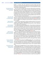
13
Figure 1. Load sharing
Load-sharing between rod/pedicle screw instrumentation and the anatomical structures of the spine during spinal
motion. In flexion-extension load is mainly transferred by the disc-fixator force couple through equal and opposite
forces. In torsion a great fraction of load is transferred by the disc. Therefore, the integrity of the anterior column is crucial
for relieving the implants from load and thus to ensure longevity. In lateral bending load transfer is mainly through the
implant.
forces acting on the posterior elements (Fig. 1). But how does the load distribu-
tion change with an insufficient anterior column support, which may be found
in various spinal disorders, e.g. vertebral body burst fractures, spondylitis, meta-
static vertebral destruction or after disc ruptures? In case of a compromised ante-
rior column, the implant must carry the majority of the load in lateral bending,
flexion, and extension (
Fig. 1). Furthermore, after discectomy and the complete
removal of the posterior structures the segmental range of motion (ROM) is still
sufficiently limited (by 64%) in flexion and extension, but torsion is only weakly
controlled and increases by more than 230% under these conditions (
Fig. 1). Tak-
ing this information into consideration, in the clinical setting postoperative lat-
eral bending (and torsion) should be avoided by the patient in any event to mini-
mize fixator loads whereas flexion and extension are mostly unproblematic pro-
vided there is a functioning anterior column.
Anterior column defects
require anterior buttressing
Combining the in-vivo measurements of implant loading taken by Rohlmann
et al., and the force flow analysis in the study of Cripton et al., global moments of
up to 30 Nm may act through the spine [21]. If instrumentation devices are
exposed to such high moments, the safe limit for many implants may be
exceeded. Therefore, in the case of a substantially unstable anterior column,
additional anterior support is critical to prevent hardware failure.
Further work is required to characterize the force and load transfer through
intervertebral devices, corpectomy cages and other stabilization constructs.
70 Section Basic Science
Posterior Stabilization Principles
The term “posterior instrumentation” is used for any surgical measure with the
implantation of a stabilization device acting on the posterior column (according
to F.W. Holdsworth’s two-column concept [43]). This is commonly carried out via
a posterior approach, which can vary depending on the surgeon’s preferences.
However, it does not necessarily mean that the device itself is exclusively acting
on the posterior spinal column. Rod/pedicle screw devices or lateral mass screws,
for example, also affect the anterior column. On the other hand, implantation of
PLIF effectively stabilizes
the anterior column
by a posterior approach
interbody cages through the spinal canal (PLIF = posterior lumbar interbody
fusion) is a measure of anterior instrumentation, although it generally makes
additional posterior stabilization, e.g. pedicle screws or translaminar screws,
necessary due to the iatrogenic destabilization of dorsal structures.
Pedicle Screw Technique
Pedicle screw/rod systems
are now well established
forsurgicaltreatment
TheintroductionofpediclescrewsbyRoy-Camillein1970[82],thesubsequent
development of the external fixator by Magerl [55], the following “fixateur
interne”byKlugerandDick[27],theangle-stableinternalAO fixator [4] and the
posterior segmental instrumentation systems [20, 51] have all dramatically
improved the outcomes of spinal fusion. In contrast to the usage of long rods, now
short segment stabilization using pedicle screws and rigid connecting plates or
rods has become possible. This technique has been proven to be safe and effective
for the surgical treatment of almost all spinal disorders such as congenital, devel-
opmental,traumatic,neoplasticanddegenerativeconditions[2,3,13,34,51].
The stabilizing potential of
screw/rod systems depends
heavily on extent and
location of instability
The stabilizing properties of pedicle screw/rod spinal fixation systems, such as
the Universal Spine System (Synthes, USA and Switzerland) [51], are not exceeded
by any other posterior systems but are critically dependent on the degree of spinal
instability and thus the pathological condition. Various biomechanical studies
have been conducted on further implant characterization and to define accurate
clinical indications. For example, after corpectomy and bisegmental instrumenta-
tion using a spacer and a cross-linked pedicle screw/rod system, motion is reduced
by up to 85% in flexion, 52% in extension, 81% in lateral bending and 51% in axial
rotation [7]. Similar results have been reported by Cripton et al. [21]. This applies
also for monosegmental instability with destruction of the posterior elements
combined with a partial dissection of the intervertebral disc. Here most other pos-
terior instrumentation devices also exceed the physiological stability, but with the
short segment fixator being the stiffest [1]. However, after complete removal of the
posterior structures combined with a complete disruption of the intervertebral
disc but with the pedicle screw instrumentation in place, the range of motion for
flexion/extension was increased by 21% compared to the intact spine. Further-
more,torsionwasonlyweaklystabilizedbyrod/pediclescrewsinposterior(facet
joint) and two-column insufficiency [21].
The stability of pedicle screw systems is derived from the solid anchorage of the
screw in the pedicle and the inherent rigidity of the connecting hardware. While
the pullout strength of pedicle screws is directly related to the bone density [39],
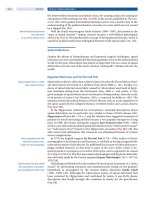
Convergent screw
positioning increases
pull-out strength
it can be increased by choosing convergent screw trajectories (
Fig. 2
). Further-
more, in the presence of anterior column instability, the avoidance of parallel ped-
icle screw insertion in short segment fixation not only increases the pull-out
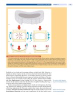
strength but also prevents an unstable “four-bar” mechanism.Thesamerationale
applies for cross-linking the rods. Here, diagonal cross-linking is favorable to the
horizontal configuration in terms of rotational stability [29, 100] (
Fig. 3
).
The material, length and diameter of the connecting rods determine their
stiffness. Compared to 7-mm rods, using 10-mm rods would increase the stiff-
ness 4.1 times and 3-mm rods would have a 30 times lower bending stiffness [80].
Spinal Instrumentation Chapter 3 71
ab
Figure 2. Pedicle screw positioning
The use of convergent screw trajectories (right) increases the pull-out strength and overall stability of pedicle screw con-
structs, in comparison with parallel screw insertion (left).
abc
Figure 3. Screw assembly
a The use of conventional parallel pedicle screws and rods for spine segments with diminished anterior integrity may be
insufficient.
b Displacement of the stabilized segment by rotation of the pedicle screws – a so-called “four-bar” mecha-
nism – may result in instability. Further stability can be achieved by the use of convergent screw trajectories and the addi-
tion of cross-linking.
c Two cross-links or at least one oblique cross-link provides better stability than one horizontal
cross-link.
However, greater deformation in smaller rods leads to greater internal stress and
may finally result in failure. More rigid rods on the other hand produce higher
internal loads in the implant, on the clamping device, and on the pedicle screws,
and thus have a higher risk of screw breakage [80]. Therefore, current implant
designs are a compromise between an absolutely rigid fixation and a minimal
risk of implant failure to provide stable fixation with a proven service life [7].
72 Section Basic Science
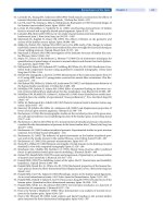
Figure4.Thoracicpediclescrew
positioning
In contrast to the standard intrapedicular screw
insertion (left pedicle), an extrapedicular screw
trajectory (right pedicle) allows a greater margin
of safety with respect to the spinal canal and
offers greater pull-out strength and stability.
Extrapedicular screw
placement in the thoracic
spine is safe and reliable
While pedicle screws have been accepted as a reliable and safe method for stabi-
lizing the thoracolumbar spine, their use in the mid and upper thoracic spine is
more complicated and risky, due to the smaller overall dimensions and greater
morphological variation of the thoracic pedicle, and the existing spinal cord at
this height. A safer alternative to the standard intrapedicular screw placement in
Lateral extrapedicular screw
positioning is safe and bio-
mechanically advantageous
in the thoracic spine
the thoracic spine is the ext rapedicular screw trajec tory (Fig. 4), first described
by Dvorak et al. [28]. The pull out strength is increased by a greater screw-angu-
lation, longer screw length, and the penetration of additional cortices. Segmental
stability has been shown to be equivalent to that of the conventional intrapedicu-
lar technique, without a higher risk of material fatigue [59].
The use of simple laminar hooks in the thoracic spine is safe with respect to the
damage of neural structures. However, hook disengagement has been reported in
scoliosis correction surgery [38]. To achieve a higher resistance to the complex
three-dimensional forces, pedicle hooks with additional supporting screws have
been developed [4, 51]. Biomechanical pull-out tests have shown that a significant
increase in failureload canbeachieved with the useof screw-augmented hooks [12].
Translaminar and Transarticular Screw Technique
Translaminar screws
effectively stabilize the
spinal segments in
conjunction with anterior
instrumentation
Transarticular screws were first used by D. King in 1948 and later modified by H.
Boucherin1959[14].Thenowwidelyacceptedtranslaminar facet joint screw
placement (
Fig. 5)wasintroducedbyF. Magerl in the 1980s [58]. Translaminar
screws (TLS) are setscrews, have a long trajectory in bone and have a favorable
direction with reference to the nerve root. TLS are mostly used supplementary to
anterior fusion techniques or in concert with posterior/posterolateral fusion
measures in degenerative disorders. Here incompetent facet joints frequently
allow pathological shear translation (olisthesis) and segmental multiplanar rota-
tion. Biomechanical testing has shown that isolated screw fixation of the facet
joints causes a moderate stabilization in all loading directions [72]. Therefore for
posterior and posterolateral spondylodesis, the combination with facet fusion is
generally recommended as it enhances stability [96].
Stand-alone interbody
cages do not sufficiently
stabilize the spine in
extension and axial rotation
Similarly, as anterior fusion (PLIF/ALIF) with stand-alone cagesisparticu-
larly weak in controlling extension and axial rotation [54], an additional fixation
is strongly recommended to ensure fusion [72]. In one study TLS were applied
complementary to paired threaded interbody cages, thereby achieving a reduced
angular motion of 30% in flexion and 60% in extension [67].
Spinal Instrumentation Chapter 3 73
ab
Figure 5. Translaminar screws
Translaminar screw positioning in the coronal (a) and the axial view (b).
However, compared to pedicle screws, the stabilizing properties of TLS are fewer,
especially in flexion and rotation [49]. Nevertheless, one should emphasize that
Thedegreeofstability
needed for optimal fusion
is still unknown
the degree of stability needed to achieve bony fusion is still not known. Further-
more, several studies have shown that solid fusion and clinical outcome are not
well correlated [33]. Nevertheless, the goal must be to achieve solid fusion and it
is much more likely that a poor clinical outcome and “failed surgery” with pseud-
arthrosis and implant failure are due to insufficient postoperative spinal stability
and improper instrumentation than to excessive stability and thus stress shield-
ing. In this context, the related question of “adjacent segment degeneration” is
discussed below in detail.
Occipitocervical Fixation
The evolution of occipitocervical fixation started with pure in-situ bone graf-
ting, after which came wire techniques, first without and later with attached steel
rods, then followed by plate/screw instrumentation in the 1990s and most
recently modular combined plate-rod/screw instrumentation [46, 99, 102]. The
major advantage of the latter is its greater stability, allowing the abandonment of
supplemental external fixation such as halo fixators or Minerva jackets.
Basically the same principles of posterior fixation as described above apply to
Lateral mass and pedicular
screw fixation is superior to
sublaminar wiring or hooks
for cervical fusions
the occipitocervical junction. Comparative biomechanical in-vitro studies have
demonstrated that lateral mass screws, pedicle screws or transarticular screws
(C1–C2) are superior to sublaminar wiring or sublaminar hooks [63]. Stability of
occipital fixation depends on whether mono- or bicortical screws are used and
the local occipital topography to the side of the screw placement. Cortical thick-
ness is greatest at the midline and the superior and inferior nuchal lines [75].
Anterior Stabilization Principles
The term “anterior instrumentation”isusedforanysurgicalmeasureforthe
implantation of a stabilization device acting on the anterior column (according to
74 Section Basic Science