Spinal Disorders: Fundamentals of Diagnosis and Treatment Part 11 pptx
Bạn đang xem bản rút gọn của tài liệu. Xem và tải ngay bản đầy đủ của tài liệu tại đây (312.75 KB, 10 trang )
F.W. Holdsworth the two-column concept [43]). The surgical approach is tradi-
tionally more or less from anterior depending on the body region and the neigh-
boring cavity. However, especially for the lumbar spine, other routes are estab-
lished such as posterior lumbar interbody fusion (PLIF) or transforaminal proce-
dures (transforaminal lumbar interbody fusion, TLIF) [60]. Even if in the past
anterior lumbar instrumentation has been questionable for some indications in
the presence of sound alternatives, in the future and with the advance of disc art-
hroplasty,anteriorsurgerywillprobablygaininpopularity.Furthermoreante-
rior fusion will most likely retain its position as a salvage procedure for failed
disc arthroplasty.
Interbody Fusion Technique
The technique of interbody or intercorporal fusion was introduced by Smith and
Robertson in 1955 for the neck [91] and much earlier for the lumbar spine for sur-
gically treating spinal deformity and Pott’s disease by Hibbs and Albee in 1911 [5,
41] and later by Burns in 1933 for stabilizing spondylolisthesis [15]. As a surgical
measure interbody fusion includes an at least partial removal of the intervertebral
disc and of the cartilaginous endplates and subsequent filling-up of the disc space
with (structured) bone graft or nowadays increasingly with artificial spacers
(cages). Cages were designed and first used by G. Bagby and D. Kuslich (BAK cage)
in the late 1980s; they were initially threaded hollow cylinders filled with bone
graft. Nowadays a variety of cage designs are available for implantation using ante-
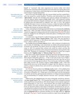
rior or posterior approaches [97, 98]. Different designs (
Fig. 6
) are available:
threaded, cylindrical cages
ring-shaped cages with and without mesh structure
box-shaped cages
Load sharing between
implant and bone graft
is essential for successful
healing
Intervertebral cages were originally proposed as stand-alone devices for ante-
riorlumbarinterbodyfusion(ALIF)orPLIF.Whilethecagesretainheightand
provide support and stability, bony fusion occurs within and/or around the cage.
However, the biomechanical requirements on these devices are very high: on one
hand they should provide enough compressive strength to keep disc space height
while stress concentration on the implant-bone interface must be minimized to
reduce penetration or subsidence into the underlying cancellous vertebral body.
On the other hand, the bone graft around and within the cage must be stressed
and strained sufficiently to evoke the biological signals (release of cytokines) for
bone formation [17, 84] (
Table 2).
In this context it is proposed that extensive stress-shielding may lead to
delayed or non-union. This conflict is reflected in most current cage geometries
and materials, but further work is required to fully understand the underlying
mechanobiology [30].
Peripheral endplate
buttressing reduces cage
subsidence
When implanting interbody devices, the partial removal of the endplate is a
prerequisite for proper graft incorporation, but a bleeding cancellous bone bed
may also compromise the support of the device, especially if limited contact areas
are present. Resistance to implant subsidence critically depends on the quality of
underlying trabecular bone [47]. However, the strength of the endplate has been
Table 2. Cage features for successful biological incorporation
adequate compressive strength to maintain disc space height
minimal stress-concentration on implant bone interface to reduce subsidence
broad contact area between bone graft and vertebral endplate
assurance of sufficient load sharing between implant and bone graft
Spinal Instrumentation Chapter 3 75
a
b
c
Figure 6. Cage designs
a The first cages had a cylindrical design and were screwed
into the endplates (Image Zimmer, Inc. used by permis-
sion).
b A very simple cage (DePuy Spine, Inc.) was popu-
larized by J. Harms consisting of a ring-shaped titanium
mesh.
c Last generation cages are box-shaped and better
buttress the endplate, which is left intact (Synthes).
showntobegreatestatitsperipheryintheposterolateral c orners [53, 64], and
therefore removal of the central endplate mostly does not compromise the
strength of the cage/bone interface significantly [93]. Based on this information,
an effective compromise between the biological and biomechanical requirements
for fusion may be achieved by choosing larger implants with more peripheral
contact areas, such as the Syncage [97].
Anterior cage positioning
provides the best stability
Similar to endplate strength the overall stiffness of the stabilized spinal seg-
ment increases by a factor of three as an interbody cage is moved within the disc
space towards the mechanically more advantageous anterior position [69].
Do not use stand-alone
lumbar interbody cages
without additional fixation
The indications for anterior fusion of the spine are various and include disci-
tis/spondylitis and vertebral burst fractures but they are still also often contro-
versial, especially for lumbar back pain. If the surgeon decides to remove the disc,
the resulting degree of instability must be estimated before choosing the type of
implant and extent of surgery. It has to be emphasized that a complete discectomy
combined with the dissection of the anterior longitudinal ligament renders the
spine substantially unstable for all loading conditions. For flexion and lateral
bending, interbody devices can restore stability profoundly. However, the major
disadvantage of these devices regardless of the approach (PLIF or ALIF) is the
poor control of extension and rotation [61].
Comparison of the strict anterior with the anterolateral implantation tech-
nique has shown that resection of the anterior annulus and anterior longitudinal
76 Section Basic Science
abc
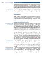
Figure 7. Cage kinematics
Stand-alone intervertebral cages for spinal fusion exhibit poor stabilization in extension. a Extension is normally partially
limited by the facet joints.
b Following the insertion of an interbody cage, the facet joints may be distracted, c thereby
increasing segmental mobility.
Overdistraction with a cage
results in facet joint
incongruency and
secondary damage
ligament is not responsible for this lack of stability [62]. This has led to the opin-
ion that stand-alone cages and anterior bone grafts cause segmental distraction
and thereby incongruence of the facet joints (
Fig. 7), which may aggravate insta-
bility [54]. The originally established concept of “distraction comp ression” by G.
Bagby [8] is thus also placed into perspective again. This indicates that, with dis-
traction of the disc space and consequent tensioned anulus fibers, a compressive
force on the cage is created. However, due to the viscoelastic anulus material
properties, the compressive effect most likely acts only for a short time [50].
Therefore, from the above-mentioned studies it can be concluded that posterior
instrumentation with pedicle screws or translaminar screws in addition to the
interbody cage must be recommended to establish the appropriate stability.
The combination of anterior
tension band instrumen-
tation and a cage is a
promising up-and-coming
technique
A potential alternative to the above-mentioned combined instrumentation is
the recent development of a novel “stand-alone” device which combines the prin-
ciple of the interbody cage with anterior tension band instrumentation (SynFix,
Synthes, USA and Switzerland). Cain et al. have compared the stabilizing proper-
ties of this screw-cage construct with conventional 360° instrumentation using
cage and pedicle screws or translaminar screws. Motion analysis demonstrated a
significant increase in segmental stiffness with the Synfix compared to cage/
translaminar screw instrumentation in flexion-extension and rotation [16].
However, testing was non-destructive and included only a few cycles. For a defi-
nite judgment the comparative biomechanical behavior under repetitive loading
(fatigue) as well as clinical results and fusion rates need to be evaluated.
Single-level stand-alone
cervical cage fixation
suffices in selected cases
In the cervical spine in contrast to the lumber spine, stand-alone interbody
cages (or structural bone grafts) are used routinely after one level discectomy,
exhibiting near 100% fusion rates. In a comparative biomechanical in-vitro
study, D. Greene et al. assessed cervical segmental stability after implantation of
interbody cages and structural bone grafts. After single-level discectomy physio-
logical segmental stability was reestablished with both techniques, but with the
cage tending to result in slightly higher stiffness [37].
Spinal Instrumentation Chapter 3 77
Corpectomy Fusion Technique
Spinal instability after single-level or even multiple-level corpectomy or verte-
brectomy is a challenging task in the biomechanical sense, especially in the lum-
bar spine. Indications are theoretically numerous and apply for myelopathy, neo-
plastic and metastatic tumor growth, chronic spondylitis or severe fracture
cases. However, the resulting instability, and thus the demand on the instrumen-
tation, strongly depends on the number of involved levels and the preserved and
functioning stabilizers. It is quite obvious that the function of incompetent or
compromised anatomical structures has to be compensated.
Severely impaired anterior
column integrity requires
a combined anterior and
posterior instrumentation
(360°)
Pure bisegmental spinal stability after single-level corpectomy in the lumbar
spine can theoretically be restored by pedicle screw systems [7]. However, in the
absence of anterior column integrity, the posterior bridge-construct bears 100%
of the load and will most likely fail even in the presence of a posterior spondylo-
desis. This phenomenon is well known from unstable burst fractures lacking
anterior support [57]. Furthermore, biomechanical tests have shown that corpec-
tomy cages alone or in combination with an anterior angle-stable plate fixation
are not capable of restoring physiological bisegmental stability. To ensure solid
bony fusion it is commonly accepted that normal physiological spinal stability
must be exceeded (to what extent is so far unknown). As segmental flexibility
with either a stand-alone cage or a cage/anterior plate combination is especially
increased in rotation, extension and lateral bending, the addition of pedicle
screw fixation must be recommended to ensure a significant increase in overall
stiffness [66]. Thus far, from the biomechanical perspective, fundamental ante-
rior instability like that found after corpectomy cannot be treated with anterior
or posterior measures alone.
Similarly to the lumbar spine, corpectomy in the cervical region is indicated
for a variety of spinal pathologies: cervical myelopathy, cervical spine trauma
and tumor manifestations. The stability after single level corpectomy and cage
implantation is comparable to the range of motion (ROM) of the intact spine in
all six degrees of freedom [85]. In one study, stability was even increased in all
directions but extension [48]. Supplemental instrumentation must therefore also
Anterior cervical plating
substantially increases
spinal stability after
corpectomy
be applied. Anterior plating adds significant stability, particularly in rotation,
which is only exceeded by posterior systems. Comparing stability of different
anterior and posterior systems demonstrated that pedicle screws are more stable
than lateral mass screws and constrained posterior systems are superior to
unconstrained systems. The highest stability was provided by combined 360°
instrumentation [85]. In a two or more level corpectomy, anterior plating may
already be insufficient (see tension band technique). In this case posterior instru-
mentation involving lateral mass or pedicle screws adds significant stability [90].
Anterior Tension Band Technique
Anterior cervical plating
bears the risk of stress-
shielding thebonegraft
and thus may cause
non-union
Anterior cervical plates act as typical tension bands during extension but func-
tion as buttress plat es during flexion. They exhibit several characteristics, e.g.
excellent visibility with implantation, prevention of graft expulsion and
increased fusion rates in multisegmental constructs. Anterior cervical plates are
either constrained or unconstrained devices and are available as dynamic plates
in various lengths.
Constrained cervical systems have a rigid, angle-stable connection between
the plate and screws, whereas unconstrained systems rely on friction generated
by compression of the plate on the anterior cortex. In biomechanical testing, con-
strained systems have shown a greater rigidity, whereas unconstrained plates can
lose a significant amount of their stability over time [92]. The surgeon has the
78 Section Basic Science
option of selecting systems with monocortical or bicortical screw fixation, often
with the same plate. Pull-out tests have demonstrated that bicortical is more sta-
ble than monocortical screw placement [92]. Further improvements in stabiliza-
tion have been made using monocortical locking expansion screws, their
strength being comparable to bicortical screws [74]. But no significant differ-
ences in stability were seen on kinematic testing [68]. However, bicortical screw
fixation still has specific indications, e.g. for multilevel stabilization, poor bone
quality or after correction of deformities, but also bears the risk of spinal cord
damage.
A three-level cervical corp-
ectomy requires anterior
and posterior instrumented
fusion
It has also been shown that the capability of anterior cervical plates to stabilize
the spine after three-level corpectomy is significantly limited after fatigue load-
ing [45], whereas no difference in stability was noted for single-level corpectomy.
Another concern regarding the cervical spine, with its inherent mobility and rel-
atively low compressive forces, is delayed or non-union (pseudarthrosis) due to
possible stress shielding of the graft. This is particularly true for the latest gener-
ation of constrained (locking) plates, with which it is more difficult to set the
graft under compression.
For this reason dynamic (semi-constrained) anterior plates were designed.
Reidyetal.haveshowninacadavercorpectomymodelthataxialloadtransmis-
sion was particularly more directed to the graft with the dynamic cervical plate
than with a static plate especially when the graft was undersized [73].
The stiffness of anterior
tension band instrumentation
differs from pedicle screws
in all loading directions
Several systems have also been developed for anterior stabilization of the
thoracolumbar spine, including the Ventrofix (Mathys Medical, Bettlach, Swit-
zerland) and the Kaneda SR (DePuy Spine, Raynham, MA, USA) systems,
which are used mostly for reconstruction in trauma, tumor and post-traumatic
kyphosis. The load is transferred through a combination of compressive or ten-
sile loading along the length of the implant and bending or torsion. Due to its
profile and their position directly on the anterior column, bending forces are
much lower than for posterior pedicle screw systems. However, their stabilizing
potential is also lower, due to a shorter effective lever arm. The relative effec-
tiveness of anterior, posterior and combined anteroposterior fixation in a cor-
pectomy model has been addressed in a study by Wilke et al. [106]. Compared
to pedicle screws, the anterior rod devices were slightly more unstable in flexion
and lateral bending. In lateral bending, the implants provided better stabiliza-
tion when the spine was bending away from the implant side, as the devices act
as a tension band. Double-rod anterior systems with or without transverse ele-
ments are superior to single rod systems, and locking screws increase the stiff-
ness.
Finally, however, in all loading directions, only combined anteroposterior fix-
ation can provide complete segmental stabilization.
Biomechanics of the “Adjacent Segment”
Adjacent segment mobility
and intradiscal pressure
increase with fusion length
Spondylodesis normally results in an unphysiologically long and stiff spinal seg-
ment.Ithasoftenbeensuggestedthatadjacentsegmentdegenerationisthe
result of increased biomechanical stress. Shono et al. [89] have shown, in an in-
vitro study, that the displacement of the adjacent motion segment is indeed
increased after fusion. In these experiments, a fixed displacement was applied to
the entire spine specimen. To produce the total displacement, the motion at the
adjacent segment must increase as the motion of the fused segment decreases
due to its stiffness. Increased segmental motion is paired with an elevated int ra-
discal pressure, which correlates with the number of fused levels [19, 42]. Rohl-
mann et al. have demonstrated, with a simplified finite element model, that
Spinal Instrumentation Chapter 3 79
application of a controlled load on rigid instrumentation had only a minor influ-
ence on stresses in the adjacent discs and endplates [80]. Nevertheless, in another
in-vitro study, application of controlled loads resulted in small but significant
increases in adjacent segment mobility [9].
The cause (mechanical
overload or natural history)
of adjacent segment
degeneration remains
unclear
It can be questioned whether “adjacent segment degeneration”isaresultof
altered biomechanical stresses or a natural progression of the disease. This issue
depends on whether adjacent segment motion is indeed increased in vivo follow-
ing fusion. An animal study by Dekutowski et al. provides some support for
increased adjacent segment motion [25]. Taken together, to date and despite
numerous clinical and biomechanical studies, it still remains unclear whether the
changed biomechanics or the progression of the natural history is responsible for
adjacent segment degeneration. However, the overall incidence of adjacent seg-
ment degeneration would likely be much higher if its cause were purely mechani-
cal. It is well accepted that disc degeneration is a multifactorial disease with
genetic and environmental factors [10]. To what exten t mechanical factors con-
tribute to the disease likely also determines whether or not disc degeneration is
initiated or aggravated adjacent to a fused segment.
Non-Fusion Principles
Non-fusion devices
may not be superior
to instrumented spinal
fusion in low back pain
The aims of non-fusion devices are the stabilization and reestablishment of nor-
mal segmental anatomy including the preservation of segmental motion and
thus without performing a spondylodesis. Several approaches have been
described to replacing certain parts of the motion segment or to adding support-
ing stabilization. Depending on the primary pathology of the mostly multifacto-
rial problem, disc arthroplasty, nucleoplasty or posterior dynamic stabilization is
performed. Several different devices for various indications are nowadays on the
market, or are currently under way, e.g. facet arthroplasty. All of these have in
common that no prospective and controlled clinical trials (class I or II evidence)
which comparatively assess the clinical outcomes are available or that the follow-
up time is too short for a definitive judgment.
Disc Arthroplasty
Disc arthroplasty preserves
spinal motion, makes bone
harvest unnecessary and
may abolish or delay
adjacent segment disease
Functional disc replacement is a logical progression in the treatment of degener-
ative disorders of the disc. Arthroplasty in the spine has several potential advan-
tages: preservation of segmental motion, lower rate of adjacent level degenera-
tion and no need for harvesting autologous bone graft.
An excellent review of the field of disc arthroplasty by Szpalski et al. highlights
the historical development and the different design concepts to date [95]. The
demands on the material properties and function of such devices are substantial.
They must not only possess sufficient strength to withstand compressive and
shear loads transmitted through the spinal column, but must also respect the
complex kinematics of intervertebral motion.
The design philosophy ofmanycurrentdiscprosthesesreflectstheevolution
of other total joint prostheses. In total knee arthroplasty (TKA), for example,
The design concepts of TKA
are still evolving
there has been the tendency towards implants which emulate physiological
motion patterns. Unlike in conventional TKA, mobile bearing knee prostheses
employ a conforming polyethylene plate which moves on the surface of a highly
polished metallic tray which itself is affixed to the tibial plateau. Due to its confor-
mity throughout the full range of motion, stresses transmitted through the poly-
ethylene and into the bone should be lower and thus reduce polymer wear and
prosthesis loosening.
80 Section Basic Science
a
bc
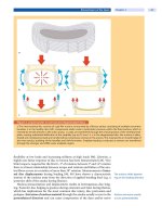
Figure 8. Center of rotation
The kinematics of the intervertebral joint is complex. a The center of rotation moves during flexion/extension, b left and
right side bending
c and left and right torsion. Current designs for intervertebral prostheses or dynamic stabilization sys-
tems aim to respect this unique characteristic of spinal motion.
Disc prostheses are
confronted with a complex
segmental spinal motion
pattern
As in the knee, motion of the natural intervertebral joint cannot be compared to
a simple ball-and-socket joint. Segmental motion in flexion and extension is a
combination of sagittal rotation plus translation. This is also referred to as the
helical axis of motion.Thus,theinstantaneous axis of rotation constantly
changes throughout the full range of motion (
Fig. 8).
This principle is reflected in the Bryan Cervical Disc System (Medtronic),
which comprises a low friction elastic nucleus located between titanium end-
plates and a sealing flexible membrane, allowing free rotation and some transla-
tion in all directions. Similarly the Charit´e artificial disc (DePuy Spine) consists
of cobalt chromium endplates and a floating polyethylene sliding core also
enabling translation and rotation. In contrast, the ProDisc (Synthes) and Maver-
ick Artificial Disc (Medtronic) are constrained devices with a single articulation,
allowing free rotation in all directions around a fixed center of rotation. Uncon-
strained devices allow a greater range of motion and theoretically prevent exces-
sive facet loads in extreme motion. In contrast constrained disc arthroplasties
may reduce shear force on the posterior elements [44]. Only comparative pro-
spective clinical trials can conclusively show if any of these concepts is advanta-
geous for the patient [31]. The Charit´e and ProDisc were the first protheseses
involved in an FDA trial (
Fig. 9).
Current disc prostheses
almost reestablish
a physiological range
of motion
As with other total joint prostheses, the stability of the prosthesis and the
motion segment likely depends on well balanced ligaments and surrounding soft
tissues. Therefore, precise operation technique with retention of stabilizing tis-
sue is essential for a good outcome. Wear of prosthesis components, as in other
arthroplasties, likely occurs. Histocompatibility was tested for titanium and
polyethylene particles in animal models, and neither material induced a strong
inflammatory host response [6, 18]. Finally, the kinematics of each new device
must be verified against representative motion patterns of the normal spine [22].
In one study by DiAngelo et al., spinal kinematics before and after implantation
of a cervical disc prosthesis (ProDisc) was compared with spondylodesis. Using
a displacement-c ontrolled protocol, with the prosthesis in place almost no alter-
ationinmotionpatternscouldberecordedcomparedtotheintactstate,unlike
in the fusion case where the adjacent segments compensated for the fused level to
Spinal Instrumentation Chapter 3 81
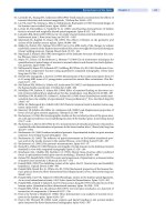
ab
Figure 9. Designs of total disc arthroplasty
Current intervertebral disc prostheses differ in the bearing material used (polyethylene or metal alloys) and have either
a fixed (constrained) center of rotation (e.g.
a Prodisc, Synthes) or follow the segmental helical axis of motion (semi-con-
strained) as in
b the Charit ´e prothesis (DuPuy Spine Inc.).
achieve full motion [26]. This is in agreement with Puttlitz et al., who demon-
strated an establishment of an approximate physiological kinetics in all six
degrees of freedom with cervical disc arthroplasty [70]. In another biomechani-
cal in-vitro study, Cunningham et al. compared the Charit´e disc prothesis with an
interbody fusion device (BAK) with and without posterior instrumentation.
Unlike interbody fusion, also in the lumbar spine the disc prosthesis exhibited a
near physiological segmental motion pattern in all axes except rotation, which
was increased [23].
Only few data exist so far about the lifetime of disc prostheses, preservation of
motion and long-term patient satisfaction. Therefore, total disc replacement still
has to establish its position against spondylodesis [24, 71, 101].
Nucleoplasty
Nucleoplasty is an intriguing
evolving new surgical
technique
In contrast to total disc arthroplasty, replacement of only the degenerated or
excised nucleus pulposus is an option offered by the Prosthetic Disc Nucleus (PDN,
Raymedica Inc., Minneapolis, USA). The PDN is a hydroactive implant which
mimics the natural fluid exchange of the nucleus by swelling when unloaded and
expressing water under compressive load. Wilke et al. [105] have shown that the
PDN implant can restore disc height and range of motion after nucleotomy to nor-
mal values. There is, however, little data on the long-term biomechanical behavior
of such implants in the intervertebral disc space, and the overall effectiveness of
replacing only the nucleus pulposus in a degenerated disc.
Posterior Dynamic Stabilization Technique
Indications for dynamic
posterior stabilizing devices
are difficult to define
Non-rigid posterior stabilization of the spine is another concept for the treat-
ment of various spinal pathologies. In 1992, H. Graf introduced the ligamento-
plasty, a posterior dynamic stabilization system consisting of pedicle screws
which were connected via elastic polyester elements [36]. The underlying theory
is the maintenance of physiological lordosis while flexion-extension motion is
restricted and therefore the respective disc is unloaded and thus “protected”.
Kinematic in-vitro studies have shown that, after laminectomy and partial
82 Section Basic Science
a b
Figure 10. Non-fusion spinal stabilization devices
a Dynamic posterior spinal stabilization with Dynesys (Image Zimmer,Inc.usedbypermisson.b Interspinous process
distraction devices (e.g. X-stop) limit extension motion and unload the facet joints. The aim is to improve functional
spinal stenosis by indirect widening of the spinal canal.
removal of the facet joint with Graf ligamentoplasty, flexibility is significantly
reduced in all directions compared to the intact state [94]. However, clinical stud-
ies report conflicting data about the clinical success [35, 56].
The stabilizing properties
of Dynesys largely exceed
physiological stability
Nowadays the most often used device is the dynamic neutralization system
(Dynesys) for the spine (Zimmer, Warsaw, USA). Dynesys (
Fig. 10a) is a non-
fusion pedicle screw system composed of titanium pedicle screws joined by poly-
carbonate urethane (PCU) spacers containing pre-tensioned polyethylene tere-
phthalate (PET) cords. With such a system, the affected segments can be dis-
tracted and disc height restored and kinematics in all planes are restricted. How-
ever, motion is not absolutely prevented, in contrast to solid fusion implants.
Schmoelz et al. compared the kinematics of Dynesys stabilized segments with an
internal fixator using destabilized cadaver specimens. They demonstrated that
Dynesys was able to improve stability in all dimensions. However, axial rotation
was poorly controlled while in lateral bending and flexion the system was as stiff
as the internal fixator. Only in extension was Dynesys able to restore the physio-
logical state [86].
Posterior dynamic systems
are challenged by the
required long lift time cycle
Freudiger et al. [32] have demonstrated that the Dynesys limits shear transla-
tion and bulging of the posterior anulus in the unstable spine segment under
physiological loading. Due to the compliance of the instrumentation, overload-
ing of adjacent segments may be prevented. However, unlike with the spondylo-
desis the instrumentation must bear certain loads throughout its whole life.
Thereby material fatigue and pedicle screw loosening may result in ultimate fail-
ure. The efficacy of such a system depends heavily on the condition of the ante-
riorcolumnandnooneknowssofarhowmuchstabilityorflexibilityisactually
needed in each particular case.
Interspinous Process Distraction Technique
The principle of implanting a spacer between adjacent spinous processes was
already used by F. Knowles in the late 1950s to unload the posterior anulus in
patients with disc herniation and thereby achieving pain relief [104]. In recent
years various systems have entered the market such as the Interspinous “U”
(Fixano, P´eronnas, France), the Diam (Medtronic, Memphis, USA), the Wallis
Spinal Instrumentation Chapter 3 83
(Spine Next, Bordeaux, France) and the X-Stop (St. Francis Medical Technolo-
gies,Concord,USA)(
Fig. 10b) systems. Only few biomechanical and no high-
quality clinical studies are currently available.
Interspinous devices
decrease extension and aim
to widen the spinal canal
All devices aim to limit motion in extension. Biomechanical testing has shown
that extension motion is indeed decreased while flexion, axial rotation and lateral
bending stay unaffected [52]. Limited extension is thought to reduce narrowing
of the spinal canal and flavum buckling [88]. Furthermore, Lindsey et al. demon-
strated an unloading of the facet joint in an in-vitro cadaver study using pressure
sensitive foil [107].
But how far the resulting increase of segmental kyphosis is compensated by
the adjacent segments and how this may affect the sagittal profile and balance in
the long term need to be evaluated in the future. However,for patients with spinal
stenosis and neurogenic claudication which improves in flexion, the interspinous
device is a feasible option especially with regard to the limited trauma with
implantation.
Recapitulation
Goals of spinal instrumentation.
The aims of spinal
instrumentation are stabilization, achievement and
maintenance of curve correction (alignment) and
facilitation of bony fusion (spondylodesis). Knowl-
edge of the underlying fundamental biomechani-
cal principles helps to prevent material failure and
thus improves surgical outcome. Several basic
properties of spinal implants have to be consid-
ered: material strength, the ability to provide seg-
mental stability and the resistance to fatigue with
cyclic loading. Unfortunately it is still unclear how
much stability is required in each particular case to
ensure spinal fusion. Generally the instrumentation
aims to exceed the physiological state, e.g. to make
the motion segment stiffer.
Loading and load sharing characteristics. Spinal
instrumentation and the stabilized spine segment
form a system which shares loads and moments.
In-vivo telemetric measures have given valuable in-
sight into device loading patterns. Forces acting on
the implant depend on the degree of instability.It
has been shown that rod/pedicle screw implants
are mainly loaded with compression forces and
bending moments. Load sharing between the im-
plant and bone graft is mandatory for successful
bone healing. In contrast, extreme stress-shielding
may result in pseudarthrosis.
Pedicle screw technique. Pedicle screw/rod instru-
mentation has been well established for the surgi-
cal treatment of almost all spinal disorders. Unless
there is a substantial incompetence of the anterior
column, pedicle screw systems provide exc ellent
stability in mono- and multisegmental applica-
tions. Choosing convergent screw trajectories and
cross-linked rods may enhance stability.
Translaminar and transarticular screws. The trans-
laminar route should be favored over the direct
transarticular trajectory in degenerative disorders
and in conjunction with anterior interbody fusion.
Occipitocervical fixation. Modular plate-rod/screw
instrumentation is available. Lateral mass screws,
transarticular screws (C1–C2) and pedicle screws
provide increased stability compared to laminar
hooks and wires. Therefore additional external sup-
port with halo fixation, etc., has mostly been aban-
doned.
Interbody fusion technique. Lumbar interbody
cages are designed to provide sufficient strength to
keep disc space height without the necessity for us-
ing structural bone grafts. Originally implanted as
stand-alone cages,whichledtonoticeablepseud-
arthrosis rates, they are nowadays routinely com-
bined with additional instrumentation (pedicle
screws/translaminar screws or anterior tension
band) due to the poor control of extension/distrac-
tion and rotation. Meticulous endplate prepara-
tion is mandatory to ensure bony fusion. Anterior
cage position is advantageous in terms of stability.
Endplate strength is highest in the periphery. In the
cervical spine, however, after single level discecto-
my and “stand-alone” cage implantation near 100%
fusion rates are achieved.
84 Section Basic Science