Spinal Disorders: Fundamentals of Diagnosis and Treatment Part 27 pps
Bạn đang xem bản rút gọn của tài liệu. Xem và tải ngay bản đầy đủ của tài liệu tại đây (345.34 KB, 10 trang )
are often unable to stay motionless for the 20 min required for a standard exami-
nation. Hip flexion, which might relieve the patient’s pain, is only possible to a
limited degree in most magnet designs. Proper analgesic medication prior to the
MR examination may be required in order to reduce patient discomfort and
pain-related motion artifacts.
Computed Tomography
CT is the modality of choice
for imaging of bone
CT has developed with amazing speed during the last few years. Spiral CT with
continuous data acquisition appeared in routine work in the mid-1990s, and
multi-detector row CT at the end of the 1990s. Initially, four detector rows were
employed which were quickly followed by 16,40 and 64 detector rows. Atthe time
of writing, this development has not yet come to an end. Compared to MR imag-
ing, CT has several advantages. CT shows bony details with a high spatial resolu-
tion.
In plane spatial resolution of CT (pixel size) is approximately 0.25–0.5 mm
(depending on the system geometry and on the reconstruction kernel selected by
the user) and is therefore better than in typical MR protocols. CT does not inter-
fere with the function of pacemakers and other electronic devices. The metal-
related artifacts present in CT are related to so-called beam-hardening, which
depends on the amount/size of implants and the atomic number of the implant.
Such artifacts may be less pronounced or in a different place when compared to
CT is the imaging modality
of choice in an emergency
situation
MR imaging. Examinations in emergency room and intensivecarepatientsare
preferably performed using CT because imaging times are shorter, patient access
is easier and no specialized (non-ferromagnetic, shielded) intensive care equip-
ment is necessary as for MR imaging.
Contrast resolution
is inferior to MRI
On the other hand, the contrast resolution of CT is much inferior to MR imag-
ing in important structures such as the intervertebral discs, cerebrospinal fluid
and soft tissue. The radiation dose is considerable in CT, e.g., 28% of the medical
radiation dose in Switzerland is generated by CT examinations [46]. CT examina-
tions of the lumbar spine (8.2 mSv) and of the sacroiliac joints (7.0 mSv) result in
a higher effective radiation dose compared to CT examinations of the cervical
(3.4 mSv) spine.
CT fluoroscopy allows for
interventional procedures
CT fluoroscopy allows real-time imaging of interventional procedures.Dur-
ing these procedures, the radiologist activates intermittent or continuous image
acquisition with a foot pedal. If necessary, the patient can be moved in the crani-
ocaudal axis using a joystick, placed within the reach of the radiologist’s elbow or
hand. In order to protect the patient and the radiologist from high radiation
doses, low-dose imaging (lower mAs) is usually performed. In addition, a
reduced number of pixels (reduced spatial resolution) and near-real-time image
reconstruction algorithms are commonly used in order to reduce acquisition
time [42]. CT fluoroscopy allows imaging of a needle or other radiopaque devices
in real-time fashion during insertion. This method is typically employed for CT
guided nerve root blocks, facet joint blocks, CT discography, injections into the
sacroiliac joints, sympathetic trunk blocks, vertebral body biopsy, and soft tissue
biopsy.
DEXA is used for the
determination of bone
mineral density
CT is one of the many available tools for bone density measurement. Bone
density within the vertebral body can be directly measured by simultaneously
scanning the vertebral body and phantoms with defined densities [15]. This
method is not commonly employed, however, for a number of reasons. The
most commonly employed method is dual energy X-ray absorptiometry
(DEXA),whichreducesradiationdoseandcostwhencomparedtoCT.Onthe
other hand, this method is a projectional method and may overestimate bone
density in the presence of spondylophytes. Dedicated small CT scanners have
Imaging Studies Chapter 9 241
pQCT allows fast losers
to be detected
been used for peripheral quantitative computed tomography (pQCT) mea-
surements [9]. Such scanners are less expensive than standard CT scanners
and provide highly reproducible results which may be used for early detection
of fast losers and for monitoring the effects of medication therapy. Other
methods mainly used for peripheral measurements (with variable predictive
value for spinal fractures) are broadband ultrasonic attenuation (BUA) [44]
and high-resolution MR imaging measurement of the trabecular bone volume
fraction [47].
Imaging Protocol
When a single slice CT unit is used, the examination needs to be restricted to a
few spinal segments. Typically, the cervical spine is imaged with thinner slices
Multi-detector CT has
improved resolution and
shortened imaging time
compared to the thoracic and lumbar spine. Multi-detector CT (MDCT) units
allow the acquisition of a large number of segments with thin slice thickness,
within the same period of time. Sagittal and coronal multiplanar reformations
(MPRs) are more easily obtained and are of better quality based on such data
sets. Typical imaging protocols in the cervical, thoracic, and lumbar, spine, as
well as for the sacroiliac joints, are shown in
Table 2.
Table 2. Imaging parameters for computed tomography
a
Single-slice CT 16-row MDCT 64-row MDCT
Cervical spine
Plane Axial axial axial
Slice thickness C0 – C3 1 mm 16×16.75 mm 64×64.6 mm
C4 – C7 2mm
Pitch C0 – C3 1.3 – –
C4 – C7 1.25
Recon. interval C0 – C3 2 mm 0.6 mm 0.7 mm
C4 – C7 2mm
Kernel soft AH 50 B 30 B 30
Kernel bone AH 91 B 50 B 50
Window soft (C/W) 250/50 280/60 360/70
Window bone (C/W) 1800/450 1500/400 1500/400
Thoracic and lumbar spine
Plane axial axial axial
Slice thickness 2–3 mm 16×16.75 mm 64×64.6 mm
Pitch 1.25–1.5 – –
Recon. interval 3 –4 mm 0.6 mm 0.7 mm
Kernel soft AB 50 B 30 B 30
Kernel bone AH 82 B 50 B 50
Window soft (C/W) 250/50 360/70 360/70
Window bone (C/W) 1800/450 1500/400 1500/400
Sacroiliac joints
Plane coronal axial axial
Slice thickness 2 mm 16×16.75 mm 64×64.6 mm
Pitch 1.25 – –
Recon. interval 3 mm 0.6 mm 0.7 mm
Kernel soft AB 50 B 30 B 30
Kernel bone AH 82 B 50 B 50
Window soft (C/W) 250/50 360/70 360/70
Window bone (C/W) 1800/450 1500/400 1500/400
a
As used in our institution
Kernel soft = image reconstruction algorithm for soft tissue; Kernel bone = image reconstruc-
tion algorithm for bone; C = center, W = width. The above algorithms are only for Siemens
CT units; differences with other manufacturers are likely
242 Section Patient Assessment
Indications
CT is superior to MR
imaging in the evaluation
of bone abnormalities
Generally, MR imaging is the advanced modality of choice in imaging of the
spine. As a screening, CT can be applied to diagnose or rule out disc herniation
particularly when an ossified herniation is suspected (
Fig. 11). However, there
are clinical situations where CT is superior to MRI. CT should be preferred to
MRI when the bony structures have to be analyzed such as fracture of the spine
(
Fig. 12) or in cases of MRI contraindications.
ab
Figure 11. CT diagnosis of disc herniation
a CT scan at the L4/5 level (soft tissue window) demonstrating a right-sided mediolateral disc herniation. b CT scan at the
L5/S1 level (soft tissue window) is superior to MRI, showing a calcified, broad-based median disc herniation.
ab
Figure 12. CT diagnosis of spinal fractures
a, b Standard radiographs demonstrate loss of height, widening of interpedicular distance and probable dorsally
extruded fragment.
Imaging Studies Chapter 9 243
cd
Figure 12. (Cont.)
c, d This is confirmed by a
CT scan with image refor-
mation.
Such indications include:
acute spinal trauma
evaluation of spinal fusion
planning of complex surgical procedures (e.g., osteotomies)
spondylolysis
complex vertebral deformities
claustrophobia and contraindications to MRI
Contraindications, Artifacts, Side Effects
CT is relatively contraindicated during pregnancy. Especially in pregnancy, but
also in all other instances, the indications for CT should be considered carefully.
Beam hardening artifacts are most commonly caused by metallic implants.
These artifacts depend on the volume, orientation and atomic number of the
implant. The artifacts are limited to the CT slices which include the metallic
implants. These artifacts are accentuated in the longitudinal direction of screws.
They appear as one or multiple thick lines which may be oriented in a sunbeam-
CT exhibits fewer artifacts
than MRI in the presence
of implants
like fashion and may cover large parts of the field of view. Typical causes of beam
hardening artifacts are extensive dental implants, screws, cages, intervertebral
disc prostheses, shoulder and hip prostheses, as well as pacemakers or drug
pumps. In the vicinity of implants, beam hardening artifacts tend to be less pro-
nounced compared to susceptibility artifacts seen on MR imaging. On the other
hand, implants located far away from the spine (for example dental implants)
may be more disturbing on CT images while MR images are not degraded in a
clinically relevant fashion.
Additional Imaging Methods
Bone Scintigraphy
Bone scans are surpassed by
MR imaging and PET
99m
Technetium polyphosphonate scintigraphy, such as
99m
Tc-methyl diphospho-
nate (MDP) scintigraphy, has been used in an almost unchanged fashion for
many years [41]. For this examination, 500–800 MBq of
99m
Tc is injected intrave-
nously and images are obtained 2–3 h after injection. The
99m
Tc distribution at
that time shows the activity of the osteoblasts and thus demonstrates bony turn-
over activity. Images acquired within a few minutes after the injection demon-
244 Section Patient Assessment
Bone scan remains a skeletal
screening modality
fortumorsorinfections
strate the vascularity of the tissue. Bone scintigraphy is mainly used as a screen-
ing tool because it demonstrates the entire skeleton in a single examination.
Bone scintigraphy may also be useful in assessment of disease activity. For local
diagnosis, however, bone scintigraphy has mainly been replaced by MR imaging,
which provides similar information regarding disease activity but adds anatomi-
cal details. The role of specialized scintigraphic methods such as
111
In,
67
Ga, or
anti-granulocyte antibody scintigraphy has declined due to the increasing use of
MR imaging, the advent of positron emission tomography (PET) and also
because some of the methods do not perform in the spine as well as in peripheral
bones due to the relatively large proportion of cell-rich hematopoietic bone mar-
row. This interferes with the detection of abnormalities such as infection and
neoplasm which are also characterized by a large number of cells. Independently
of this discussion, bone scintigraphy has a limited role in detecting Langerhans’
cell histiocytosis and multiple myeloma [21], which both tend to be inconspicu-
ous on
99m
Tc bone scintigraphy.
Positron Emission Tomography
PET is increasingly used for
staging of tumors and for
the assessment of infection
Imaging with PET requires expensive equipment, especially if combined with a
CT scanner (PET-CT). The tracers required for PET have short half-life periods
of between a few minutes (
15
O: t
1/2
=2.1 min) and approximately 2 h (
18
F: t
1/2
=110 min). Therefore, the cyclotron generating the tracers has to be within an
adequate distance of the PET scanner. A large number of different tracers are
available. However, PET is typically performed with
18
FDG (
18
fluorodeoxyglu-
cose). Doses of between 200 and 600 MBq of
18
FDG are intravenously injected.
Scanning starts after a delay of 30–40 min [40]. This method demonstrates areas
of increased glucose metabolism which typically are present in tumors and infec-
tion. PET can provide images of large parts of the body within a single examina-
tion and is increasingly used for staging of tumors but also for the assessment of
infection. Its role is not limited to bone but may be even more important for
imaging of soft tissue, lymph nodes and abdominal organs.
Myelography
Myelography can be
associated with serious
side effects
For lumbar myelography the injection of contrast is typically performed at the
L2/3 level with a thin (22G) needle. Rounded needles have been advocated in
order to reduce traumatizing of the dura and nerve roots but are not universally
used. Application of 2.5–4.5 g iodine (8–15 ml of a contrast agent containing
300 mg/ml iodine) results in a sufficient intrathecal contrast [18]. Water-s oluble ,
non-ionic, iso-osmolar types of contrast agent produce the fewest side effects.
Side effects mainly include pain, which may be similar or different from the pain
usually experienced. Pain is most commonly found in patients with severe steno-
sis of the spinal canal. Severe side effects of myelography such as seizures are
infrequent [38]. However, the injection of ionic contrast media is strictly contra-
indicated because asevere form of seizure called “ascending tonic-clonic seizure”
has been reported after inadvertent intrathecal injection of such ionic contrast
agents [5, 38]. Prolonged side effects are most often related to the puncture itself.
Liquor leakage throughtheduralpuncturesitecancausesevereheadache,which
can last for several days or even weeks. Blood patches with approximately 8 ml of
the patient’s own blood have been suggested for treatment of prolonged symp-
toms.
Immediately after intrathecal contrast administration, radiographs are
obtained with the patient in the prone and lateral decubitus position as well as
prone oblique radiographs (approximately 15°/30°, commonly positioned under
Imaging Studies Chapter 9 245
a
b
c
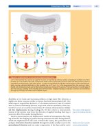
Figure 13. M yelography and CT
myelography
Positional radiographs in a flexion and b extension,
demonstrating segmental stenosis of the spinal
canal, most pronounced at the L3/4 level.
c CT at
the L3/4 level, confirming stenosis of the spinal
canal. Gas within degenerated disc.
Functional examination
rarely has a diagnostic
or therapeutic impact
fluoroscopic control, in order to better demonstrate the entire course of nerve
roots). Functional examination in flexion and extension does not appear to have
an impact on the diagnostic and therapeutic decision-making in the presence of
an MRI examination and is not routinely done in our center [36, 48, 50]. Myelo-
graphy is commonly combined with CT of the spine (CT myelography) (
Fig. 13).
The acquisition parameters are similar to those for standard CT(see CT chapter).
Compared to standard CT, intrathecal contrast medium outlines the intradural
space and any filling defects within this space or abnormalities impinging on the
duralsac.Stenosisofthespinalcanalorthelateralrecessesaswellastheinflu-
ence of disc herniation on intradural structures may even be more clearly dem-
onstrated than by MR imaging.
Direct cervical myelography with craniocervical injections has largely been
replaced by MR imaging or CT myelography obtained after lumbar injection.
Indications for myelography or CT myelography in the era of MRI are very
rare and are restricted to the following conditions:
postoperative spine with marked susceptibility artifacts in MRI
unclear conditions with suspected functional stenosis
In all other cases MRI should provide enough information about foraminal or
spinal canal stenosis. Only in a few cases is additional CT without intrathecal
contrast administration necessary to distinguish between osteophyte formation
and disc protrusion within the intervertebral foramen, mainly in the cervical
spine.
MR myelography (MR imaging performed after intrathecal injection of MR
contrast media) has rarely been employed but appears to be feasible. No adverse
The diagnostic value
of MR myelography
is questionable
reactions other than those known from conventional myelography were found in
these patients. However, the technique of intrathecal administration of gadopen-
tetate and related contrast media has so far not been approved by the responsible
state agencies and the additional diagnostic effect is questionable.
246 Section Patient Assessment
Image Guided Injections
Image guided injections such as nerve root blocks or facet joint injections are
discussed in Chapter
10 .FluoroscopyandCT(possiblyCTfluoroscopy)are
most commonly employed as guiding methods for such procedures although MR
imaging has also been suggested for this purpose.
Ultrasonography
Sonography has a limited
role in imaging of the spine
Ultrasonography does not play an important role in imaging of the spine. Retro-
peritoneal abnormalities are commonly examined from ventrally with a trans-
ducer suitable for abdominal imaging (commonly a curved array transducer
with a frequency of 3.5–5 MHz). The evaluation of the contents of the spinal
canal cannot easily be performed sonographically. The bony surfaces surround-
ing the relevant structures prevent a consistent evaluation.
Sonography has been used to guide periradicular injections in the lumbar
spine [13] and it has also been used as guidance for lumbar sympathetic trunk
blocks [20]. There may be a role for intraoperative sonography in spinal cord
tumors or malformations but probably not typically for the evaluation of degen-
erative disc disorders and other common spine abnormalities [12].
Sonography is routinely
used for the assessment
of cervical arteries
Duplex sonography and color Doppler sonography are excellent tools for eval-
uation of the vertebral and carotid arteries [3]. The vertebral arteries can be
injured in different types of spinal trauma (such as vertebral artery dissection in
cervical fractures extending into the transverse foramen). Alternatively, MR
imaging (loss of the flow void within the artery), MR angiography with intrave-
nous injection of MR contrast media or CT angiography after injection of iodine
containing contrast media can be obtained to demonstrate abnormalities of the
vertebral arteries [45].
Indications for Spinal Imaging
There are no universally accepted and standardized indications for the applica-
tion of imaging modalities in spinal disorders. However, the following imaging
algorithmsareenhancedbyevidencefromtheliteratureandresemblea“best
practice” approach as used in our spine center.
Acute Low Back Pain Without Radicular Symptoms, Without Trau ma
In acute non-specific
low back pain, imaging
is usually not necessary
In acute low back pain, imaging is not recommended dur ing the first 6 weeks of
a pain episode if:
spinal infection or
tumor
can be excluded.
Upright anteroposterior and lateral radiographs of the lumbar spine are the
basis of imaging. Radiographs give an overview and demonstrate bony details and
indirect signs of disc degeneration including reduced disc height, sclerosis of the
vertebralendplates,spondylophytesaswellasosteoarthritisofthefacetjoints.In
Standard radiographs
demonstrate transitional
anomalies which may be
overlooked on MRI
cases of anomalies of the transition between the lumbar spine and the sacrum,
conventional radiographs are important for definition of the lumbar segments.
Calcifications are easily recognizable on standard radiographs. Standard radio-
graphs are obtained with the patient in the upright position, which is only possi-
ble with very few MR scanners. In addition, degenerative or inflammatory find-
ings of the sacroiliac joints are often recognized on these standard examinations.
Imaging Studies Chapter 9 247
Specific MR imaging questions are related to the presence of:
disc degeneration
disc herniation
nerve root compromise
facet joint osteoarthritis
spinal canal stenosis
spondylodiscitis
rare findings (e.g., intra- and extradural tumors)
Sacroiliac disorders may be
overlooked using standard
MRI protocols
Suspected abnormalities of the sacroiliac joint should be specifically mentioned
in the request for the MR examination because the imaging protocol has to be
adapted. (Angled) coronal or axial images covering the entire sacroiliac joint as
well as sequences able to recognize inflammatory disease such as STIR (short TI
inversion recovery) or contrast-enhanced T1 W fat-suppressed sequences are
added in this situation.
The use of MR imaging without standard radiographs may be considered
when abnormalities are suspected which are not typically associated with bone
abnormalities.
CT and myelography are not relevant in acute low back pain. Imaging guided
nerve root blocks or facet joint blocks may be useful for obtaining more precise
topographical diagnostic information, for determination of the relevance of MR
abnormalities and for therapeutic purposes (see Chapter
10 ).
Acute Low Back Pain With Radicular Symptoms
MR imaging is superior
to CT for the assessment
of radiculopathy
Imaging considerations are similar to those described above. The difference is in
timing. Imaging is performed at the beginning of the diagnostic work-up. In the
presence of motor weakness (M3 and worse) imaging is performed as an emergency
examination. MR imaging usually represents the method of choice because it dem-
onstrates the location and extent of nerve root compromise. Standard radiographs
are not necessary for the initial analysis but should be obtained prior to surgery.
There are several disc herniation classification systems (see Chapter 18 )cur-
rently in use [6, 7, 22]. Today, the most frequently used system is the one suggested
by Modic and coworkers [22]:
normal: no disc extension beyond interspace (DEBIT)
bulging: circumferential, symmetric DEBIT around the endplate
protrusion: focal or asymmetric DEBIT into the canal, the base against the
parent disc is broader than any other diameter of the protrusion
extrusion: focal, obvious DEBIT, the base against the parent disc is narrower
than the diameter of the extruding material itself
sequestration: the extruded material has lost its connection to the parent disc
Oftenmoreimportantthanthedescriptionoftheshapeoftheintervertebraldisc
is its influence and relation to the adjacent nerve roots, which is crucially depen-
dent on the width of the spinal canal [10]. Pfirrmann et al. [29] showed good inter-
observer reliability in following the nerve root compromise classification system
(see Chapter
18 ):
no compromise: normal epidural fat layer visible between nerve root and disc
contact to nerve root: no epidural fat layer visible between nerve root and
disc; nerve root is in normal position and is not dorsally deviated
dev iation of nerve root: nerve root is displaced dorsally by disc
com pression of nerve root: nerve root is compressed between disc and the
wall of the spinal canal; it may appear flattened or be indistinguishable from
disc material
248 Section Patient Assessment
CT is inferior to MRI in this situation and is only indicated in the case of contra-
indications for MRI. Imaging guided treatment such as nerve root blocks or facet
joint blocks may be employed for therapeutic rather than diagnostic purposes.
Spinal Cord and Cauda Compression Syndromes
Spinal cord and cauda
equina compression
represent an emergency
indication for MR imaging
A suspected spinal cord and cauda equina compression syndrome is an emergency
situation requiring immediate MR imaging. If no clear diagnosis such as a large
disc herniation or intraspinal hemorrhage can be made, a tumor within the spinal
cord has to be excluded. In such cases, contrast enhanced MRI should be obtained
and imaging should be extended to include the thoracic and cervical spine.
Acute Trauma
Trauma is typically imaged
with standard radiographs
and CT
Imaging starts with standard radiographs in two planes. If conventional radio-
graphs lead one to suspect vertebral fracture or if they are equivocal, CT with
multiplanar reformations is employed. Increasingly, CT is even used as a primary
examination, especially in polytraumatized patients. If a multidetector CT
(MDCT) is available, the acquired data sets can be used for reconstruction of the
spine with adequate image quality [32]. MR imaging can be necessary for identi-
fication of radiologically occult fractures (
Figs. 14 – 16) and bone contusions.
MRI reveals additional information regarding:
herniated disc material
epidural or intramedullary hematoma (
Fig. 15)
post-traumatic myelopathy
spinal cord transsection (
Fig. 15)
injury to the posterior support structures
ab
c
Figure 14. Acute trauma
a Sagittal T1 W and b sagittal STIR sequences as well as c axial T2 W sequence of a patient with an acute trauma of the
thoracic spine. Anterior collapse of the vertebral body is visible in all sagittal sequences and posterior dislocation of a
broad-based fragment into the spinal canal (arrowheads). Caused by edema and hemorrhage, there is low signal within
the bone marrow in the T1 W (curved arrow) image. In the fluid-sensitive STIR sequence, edema is much more conspi-
cuous (black arrow).
Imaging Studies Chapter 9 249
ab
c
Figure 15. Spinal cord lesion
a Sagittal T1 W and b T2 W sequences as well as c axial T2 W sequence of the thoracic spine after a car accident. Anterior
collapse of the vertebral body and bone marrow edema is visible in both sagittal sequences (asterisk). There is disruption
of the spinal cord and dislocation (curved white arrows). There is hemorrhage and myelopathy within the spinal cord
(straight black arro w). Hemorrhage can be seen in the anterior epidural space (arrowheads) and also in the posterior epi-
dural space (straight white arrow). The dural sac is compressed (curved black arrows).
abc
Figure 16. MRI in acute and old osteoporotic vertebral fractures
a Sagittal T1 W and b T2 W sequences as well as c sagittal STIR sequence of the thoracic spine in an osteoporotic patient.
There is collapse of three different vertebral bodies. The acute fracture (asterisk) of one vertebral body can be identified
by the low signal in the T1 W (asterisk) sequence and high signal within the bone marrow in T2 W (black arrow) and STIR
(white arrow) sequences. Only a slight signal increase near the endplate of the adjacent vertebral body is visible in the
STIR sequence (curved arrow), which can be caused by degeneration or some minor infraction. There is also an old verte-
bral body fracture (arrowhead) visible without bone marrow signal alterations.
250 Section Patient Assessment