Signaling System No.7 Protocol Architecture And Sevices part 2 ppt
Bạn đang xem bản rút gọn của tài liệu. Xem và tải ngay bản đầy đủ của tài liệu tại đây (48.83 KB, 6 trang )
Subscriber Signaling
Subscriber signaling takes place on the line between the subscribers and their local
switch. Most subscribers are connected to their local switch by analog subscriber
lines as opposed to a digital connection provided by an Integrated Services Digital
N
etwork (ISDN). As a result, subscriber signaling has evolved less rapidly than
network signaling.
Subscriber signals can be broken down into the following four categories:
• Address Signals
• Supervisory Signals
• Tones and Announcements
• Ringing
A
ddress Si
g
nals
Address signals represent the called party number's dialed digits. Address signaling
occurs when the telephone is off-hook. For analog lines, address signaling is either
conveyed by the dial pulse or Dual-Tone Multiple Frequency (DTMF) methods.
Local switches can typically handle both types of address signaling, but the vast
majority of subscribers now use Dual-Tone Multi Frequency (DTMF), also known
as touch-tone.
The precursor to (DTMF) was dial pulse, which is also known as rotary dialing. In
rotary dialing, the address signals are generated by a dial that interrupts the steady
DC current at a sequence determined by the selected digit. The dial is rotated
clockwise, according to the digit selected by the user. A spring is wound as the dial
is turned; when the dial is subsequently released, the spring causes the dial to rotate
back to its original resting position. Inside the dial, a governor device ensures a
constant rate of return rotation, and a shaft on the governor turns a cam that opens
and closes switch contact. The current flowing into the telephone handset is
stopped when the switch contact is open, thereby creating a dial pulse. As the dial
rotates, it opens and closes an electrical circuit.
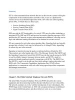
The number of breaks in the string represents the digits: one break for value 1, two
b
reaks for value 2, and so on (except for the value of 0, which is signaled using ten
breaks). The nominal value for a break is 60 ms. The breaks are spaced with make
intervals of nominally 40 ms. As shown in Figure 1-2
, consecutive digits are
separated by an inter-digit interval of a value greater than 300 ms.
Figure 1-2. Dial Pulse Address Signals
[View full size image]
The rotary dial was designed for operating an electromechanical switching system;
the speed of the dial's operation was approximately to match the switches'
operating speed.
DTMF is a modern improvement on pulse dialing that first appeared during the
1960s and is now widespread. A DTMF signal is created using a pair of tones, each
with a different frequency. It is much faster than the previous pulse method and
can be used for signaling after call completion (for example, to operate electronic
menu systems or activate supplementary services, such as a three-way call). The
standard DTMF has two more buttons than dial pulse systems: the star (*) and the
p
ound, or hash (#) buttons. These buttons are typically used in data services and
customer-controlled features. The CCITT has standardized the DTMF frequency
combinations, as shown in Table 1-1
. For additional information regarding the
CCITT, see Chapter 2
, "Standards."
Table 1-1. Tones Used to Create DTMF Signals
1209 Hz 1336 Hz 1477 Hz 1633 Hz
697 Hz 1 2 3 A
770 Hz 4 5 6 B
852 Hz 7 8 9 C
941 Hz * 0 # D
The fourth column (1633 Hz) has several special uses that are not found on regular
telephones. The four extra digits were used on special handsets to designate the
p
riority of calls on the Automatic Voice Network (AUTOVON), the U.S. military
p
hone network that has since been replaced with the Defense Switched Network
(DSN). In AUTOVON, the keys were called Flash, Immediate, Priority, and
Routine (with variations) instead of ABCD. Telephone companies still use the
extra keys on test handsets for specific testing purposes.
All modern telephone handsets support both DTMF and dial pulse. Because an
electronic handset has buttons rather than a rotary dial, the numbers are temporally
stored in the telephone memory to generate pulse dialing. The handset then
transmits the dial pulses. This arrangement is sometimes known as digipulse.
S
upervisor
y
Si
g
nals
A telephone has two possible supervision states: on-hook or off-hook. On-hook is
the condition in which the telephone is not in use, which is signaled when the
telephone handset depresses the cradle switch. The term on-hook comes from the
days when the receiver part of the telephone rested on a hook. The telephone enters
the off-hook condition when the handset is lifted from its cradle, thereby releasing
the cradle switch and signaling to the exchange that the subscriber wishes to place
an outgoing call.
Residential systems worldwide use a change in electrical conditions, known as
loop start signaling, to indicate supervision signals. The local switch provides a
nominal –48 V direct current (DC) battery, which has the potential to flow through
the subscriber line (between the local switch and the subscriber). When a telephone
is off-hook, DC can flow in the subscriber line; when a telephone is on-hook a
capacitor blocks the DC. The presence or absence of direct current in the
subscriber's local switch line determines the telephone's supervision state. Loop
start systems are adequate for residential use, but a problem known as glare makes
loop start unacceptable in typical business applications in which private exchanges
(PBXs) are used. PBXs use a system known as ground start signaling, particularly
in North America.
Ground start systems combat glare by allowing the network to indicate off-hook
(seizure) for incoming calls, regardless of the ringing signal. This reduces the
p
robability of simultaneous seizure, or glare, from both ends. Ground start requires
both ground and current detectors in customer premise equipment (CPE).
Tones and Announcements
Tones and announcements are audible backward signals, such as dial tone, ring
back, and busy-tone, that are sent by a switch to the calling party to indicate a call's
p
rogress. Table 1-2 shows the call progress tones that are used in North America.
Table 1-2. Call Progress Tones Used in North America
Tone Frequency (Hz) On Time
(Sec)
Off Time
(Sec)
Dial 350+440 Continuous
Busy 480+620 0.5 0.5
Ring back, Normal 440+480 2 4
Ring back, PBX 440+488 1 3
Congestion (Local) 480+620 0.3 0.2
Congestion (Toll) 480+620 0.2 0.3
Howler (Receiver wrongly
off-hook)
1400+2060+2450+2600 0.1 0.1
Forward signals refer to signals that transfer in the direction of call establishment,
or from the calling party to the called party. Backward signals refer to signals that
transfer in the reverse direction.
R
in
g
in
g
Ringing is a forward signal sent by the switch to the called subscriber to indicate
the arrival of a call. It is known more specifically as power ringing to distinguish it
from audible ringing, which is played to the calling party to alert him that the
called party phone is ringing. Each country has a ringing pattern, which is known
as the cadence. In North America the pattern is two seconds on, four seconds off.
N
ote
t
hat audible and power ringing are not synchronized. This is why, on a rare
occasion, a caller is already on the line when you lift the handset. This situation
generally causes confusion because the calling party, who has heard audible
ringing, is unaware of the problem since the problem occurs because the caller's
switch does not generate an independent ringing signal for each line. Instead, it
generates one signal that is applied to whichever lines are to be played audible
ringing. Therefore, if you have an incoming call, the switch must wait until the
next on-cycle to ring your telephone. If you happen to pick up the telephone during
the few off-cycle seconds and a call has just come in, you have answered a call
before the exchange has had the opportunity to alert you of the incoming call. In
N
orth America, the silent period during which inbound calls cannot be announced
is 3.9 seconds. Countries that use a short period of silence in the ringing cadence
are less susceptible to this problem.
N
OTE
If you are one of those people who say that you will call home and let the
telephone ring twice when you get to your destination safely, note that you have no
guarantee that the telephone will actually ring twice—or even ring at all. You
might hear two rings, but that does not mean the called party will hear two, or even
any, rings because their power ringing pattern might be in an off period.
The problems associated with the lack of synchronization between the calling and
called party is typically addressed in North American non-residential systems
(PBX systems) by using ground start rather than loop start. Other countries often
employ a simple technique known as ring splash. With ring splash, a PBX issues a
brief ringing tone within a few hundred milliseconds of the trunk being seized (the
incoming call), after which normal ringing cadence resumes. The downside to this
solution is that the ringing cadence sounds strange because it is not synchronized
with the initial ring.
N
etwork Si
g
nalin
g
As previously described, network signaling takes place between nodes in the core
network. This is generally from the local switch, through the core network, and to
the destination local switch—in other words, between the calling and the called
p
arty switch.
Figure 1-3
shows where subscriber and network signaling occur in the PSTN.
Figure 1-3. Subscriber and Network Signaling
[View full size image]
For obvious reasons, the signaling system employed on the local loop (between the
subscriber and the local switch) differs from that which is used in the core network.
The subscriber must only generate a limited number of signals: on or off hook,
called party digits, and possibly a few commands for supplementary services. In
comparison, a modern core network must perform very complex signaling, such as
those to support database driven services like Local Number Portability (LNP),
credit or calling card validation, and cellular roaming. Therefore, subscriber
signaling systems are simple compared to modern network signaling systems.
N
etwork signaling was previously implemented using Channel Associated
Signaling (CAS) techniques and systems. However, for the past two decades, it has
been replaced with Common Channel Signaling (CCS) systems. Apart from a rare
trace of Signaling System No. 6 (SS6) signaling, System No. 7 (SS7) is almost the
exclusive CSS system; thus, CCS can almost be taken to refer exclusively to the
use of SS7. The remaining sections of this chapter discuss CAS and CCS methods.