Signaling System No.7 Protocol Architecture And Sevices part 4 potx
Bạn đang xem bản rút gọn của tài liệu. Xem và tải ngay bản đầy đủ của tài liệu tại đây (44.98 KB, 6 trang )
Common Channel Signaling (CCS)
CCS refers to the situation in which the signaling capacity is provided in a
common pool, with the capacity being used as and when necessary. The signaling
channel can usually carry signaling information for thousands of traffic circuits.
In North America, signaling can be placed on its own T1 carrier even though it
only takes up one timeslot. This means that two physical networks, "speech" and
"signaling," can have different routings. (Please refer to Chapter 5
for a description
of carriers and timeslots.) Alternatively, the signaling might exist on a carrier with
other user traffic, depending on the network operator.
Outside of North America, the signaling is placed in its own timeslot on an E1
(that is, logically rather than physically separated). The other timeslots on E1 are
for user traffic—apart from TS0, which is used for synchronization. E1 systems
tend to use the TS16 timeslot for signaling; some core network equipment ignores
TS16, expecting it to be used for signaling traffic because it has historically been
the timeslot for digital CAS signaling.
The only CCS systems that have been implemented to date are Signaling Systems
N
o. 6 and No. 7 (SS6 and SS7). The ITU for the international network originally
standardized SS6, but they saw limited deployment. AT&T nationalized SS6 for
the North American network and called it Common Channel Interoffice Signaling
(CCIS) No. 6. SS6 saw a limited deployment after the mid-1970s because it had far
less bandwidth and a much smaller packet size than SS7. In addition, its
evolutionary potential was severely limited because it was not a layered protocol
architecture.
CCS systems are packet-based, transferring over 200 bytes in a single SS7 packet,
as opposed to a few bits allocated to act as indicators in digital CAS. The signaling
information is transferred by means of messages, which is a block of information
that is divided into fields that define a certain parameter or further sub-field. The
signaling system's specifications (Recommendations and Standards) define the
structure of a message, including its fields and parameters.
Because CCS is packet-based and there is not a rigid tie between the signaling and
the circuits it controls, it can operate in two distinct ways. These two distinct ways
are circuit-related signaling and non-circuit-related signaling.
Circuit-Related Signaling
Circuit-related signaling refers to the original functionality of signaling, which is to
establish, supervise, and release trunks. In other words, it is used to set up, manage,
and clear down basic telephone service calls. Circuit-related signaling remains the
most common mode of signaling. As it is with CAS, signaling capacity is not pre-
allocated for each traffic circuit. Rather, it is allocated as it is required. Each
signaling message is related to a traffic circuit. Because no dedicated relationship
exists between the circuits and the signaling, it is necessary to identify the traffic
circuit to which a particular signal message refers. This is achieved by including a
circuit reference field in each signaling message.
N
on-Circuit-Related Signaling
N
on-circuit-related signaling refers to signaling that is not related to the
establishment, supervision, and release of trunks. Due to the advent of
supplementary services and the need for database communication in cellular
networks and Intelligent Networks, for example, signaling is no longer exclusively
for simply setting up, managing, and clearing down traffic circuits. Non-circuit-
related signaling allows the transfer of information that is not related to a particular
circuit, typically for the purpose of transmitting both the query and response to and
from telecommunication databases. Non-circuit-related signaling provides a means
for transferring data freely between network entities without the constraint of being
related to the control of traffic circuits.
Common Channel Signaling Modes
A signaling mode refers to the relationship between the traffic and the signaling
p
ath. Because CCS does not employ a fixed, deterministic relationship between the
traffic circuits and the signaling, there is a great deal of scope for the two to have
differing relationships to each other. These differing relationships are known as
signaling modes.
There are three types of CCS signaling modes:
• Associated
• Quasi-associated
• Non-associated
SS7 runs in associated or quasi-associated mode, but not in non-associated mode.
Associated and quasi-associated signaling modes ensure sequential delivery, while
non-associated does not. SS7 does not run in non-associated mode because it does
not have procedures for reordering out-of-sequence messages.
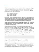
Associated Signaling
In associated mode, both the signaling and the corresponding user traffic take the
same route through the network. Networks that employ only associated mode are
easier to design and maintain; however, they are less economic, except in small-
sized networks. Associated mode requires every network switch to have signaling
links to every other interconnected switch (this is known as a fully meshed network
design). Usually a minimum of two signaling links are employed for redundancy,
even though the switched traffic between two interconnected switches might not
j
ustify such expensive provisioning. Associated signaling mode is the common
means of implementation outside of North America. Figure 1-4
illustrates the
associated concept.
Figure 1-4. Associated Mode
Quasi-Associated Signaling
In quasi-associated mode, signaling follows a different route than the switched
traffic to which it refers, requiring the signaling to traverse at least one
intermediate node. Quasi-associated networks tend to make better use of the
signaling links; however, it also tends to create a more complex network in which
failures have more potential to be catastrophic.
Quasi-associated signaling can be the most economical way of signaling for lightly
loaded routes because it avoids the need for direct links. The signaling is routed
through one or more intermediate nodes. Signaling packets arrive in sequence
using quasi-associated signaling because the path is fixed for a given call (or
database transaction) at the start of a call (or transaction). Figure 1-5
shows the
quasi-associated signaling mode, which is the common means of implementation
within North America.
Figure 1-5. Quasi-Associated Mode
N
on-Associated Signaling
Because the path is not fixed at a given point in time in non-associated mode, the
signaling has many possible routes through the network for a given call or
transaction. Therefore, the packets might arrive out of sequence because different
routes might have been traversed.
SS7 does not run in non-associated mode because no procedures exist for
reordering out-of-sequence messages. Associated and quasi-associated signaling
modes assure sequential delivery, while non-associated signaling does not. Quasi-
associated mode is a limited case of non-associated mode, in which the relative
p
ath is fixed.
< Day Day Up >
< Day Day Up >
Summary
CCS has evolved to address the limitations of the CAS signaling method. CCS has
the following advantages over CAS:
• Much faster call set-up time
• Greater flexibility
• Capacity to evolve
• More cost effective than CAS
• Greater call control
Most CCS calls can be set up in half the time it takes to set up CAS calls. CCS
achieves greater call control because no contention exists between signaling and
user traffic as it does with in-band CAS. Because the subscriber cannot generate
p
articular signals intended for inte
r
-switch (core network) signaling, CCS offers a
greater degree of protection against fraud than analog CAS methods.
CCS has the following disadvantages in comparison to CAS:
• CCS links can be a single point of failure—a single link can control
thousands of voice circuits, so if a link fails and no alternative routes are
found, thousands of calls could be lost.
• There is no inherent testing of speech path by call set-up signaling, so
elaborate Continuity Test procedures are required.
< Day Day Up >
< Day Day Up >
Chapter 2. Standards
Standards are documents containing agreements reached by standards bodies
responsible for that particular area of telecommunications. They are the result of
study, discussion, and analysis. Standards may be endorsed at different levels—
company, national, regional, and international—as appropriate. This chapter
p
rovides an overview of the organizations that set Signaling System No. 7 (SS7)
standards at the national, regional, and international levels.
The standards process works through agreement among relevant experts from
across a spectrum of private and public sectors. These experts debate, contribute
views, and investigate, often with a multitiered political backdrop, to arrive at an
agreed-upon specification. The process of getting a consensus from different
experts after working through the technical issues almost always leads to a better
specification in comparison to one developed by a single vendor or government
department. A consensus-based specification takes longer to produce than a single-
p
arty specification approach because of the time-consuming nature of multiparty
discussions. Although the process might be somewhat slower, it leads to a superior
specification that will be supported by a wide base of manufacturers—bringing
with it interoperability.
The fact that Internet, wireless, and fixed-line standards are all being addressed by
the SS7/C7 standards bodies is a sign of the central role that SS7/C7 plays in the
convergence of today's voice and data networks. Until the early 1990s, largely
separate worlds existed for telecommunications standards and for Internet
standards. These two worlds are now intersecting, creating the need for additional
standards to address new architectures, protocols, and features.
Test specifications are used to facilitate the standards process by helping validate
that equipment conforms to the documented standard(s). Testing is normally
p
erformed by an independent organization. Quite often this happens to be a
department of an incumbent or private company that has been spun off. C7/SS7
testing is discussed in Chapter 16
, "SS7 Testing."
This chapter begins with a historical outline of the development of international
telephony standards. It then details the standards bodies, beginning at the
international level, moving into the regional level, and finishing at the national
level.