Signaling System No.7 Protocol Architecture And Sevices part 9 potx
Bạn đang xem bản rút gọn của tài liệu. Xem và tải ngay bản đầy đủ của tài liệu tại đây (63.83 KB, 15 trang )
Pre-SS7 Systems
The following are the main systems that preceded SS7:
• CCITT R1 (regional 1) was deployed only on a national level. R1 is a
Channel Associated Signaling (CAS) system that was employed in the U.S.
and Japan. It uses multifrequency (MF) tones for signaling. It is no longer in
general operation, although some remnants might remain in the network.
• CCITT R2 (regional 2) was deployed only on a national level. R2 is a CAS
system that was employed in Europe and most other countries. It used
Multifrequency Compelled (MFC) for signaling; it compelled the receiver to
acknowledge a pair of tones before sending the next pair. It is no longer in
general operation, although some remnants might remain in the network.
• Signaling systems that have been deployed for both national and
international (between international switches) signaling have progressed
from CCITT #5 (C5) to CCITT #6 (C6) and finally to CCITT #7 (C7):
- C5 (CCITT Signaling System No. 5) is a CAS system standardized in 1964
that has found widespread use in international signaling. It is still in use
today on a number of international interfaces. National implementations are
now scarce, except in less-developed regions of the world, such as Africa,
which makes extensive use of the protocol. C5 can be used in both analog
and digital environments. In an analog setting, it uses tones for signaling. In
a digital setting, a digital representation of the tone is sent instead (a pulse
code modulation [PCM] sample).
- C6 (CCITT Signaling System No. 6), also called SS6, was the first system
to employ Common Channel Signaling (CCS). It was standardized in 1972.
(CAS and CCS are explained in Chapter 1
, "The Evolution of Signaling.")
C6 was a pre-OSI model and as such had a monolithic structure as opposed
to a layered one. C6 was a precursor to C7 and included the use of data links
to carry signaling in the form of packets. It had error correction/detection
mechanisms. It employed a common signaling channel to control a large
number of speech circuits, and it had self-governing network management
procedures. C6 had a number of advantages over C5, including
improvements in post-dial delay and the ability to reject calls with a cause
code. The use of locally mapped cause codes allowed international callers to
hear announcements in their own language. Although C6 was designed for
the international network, it was not as widely deployed as C5. However, it
was nationalized for the U.S. network and was deployed quite extensively
under the name Common Channel Interoffice Signaling System 6 (CCIS6)
in the AT&T network. C6 was introduced into the Bell system in the U.S. in
1976, and soon after, Canada. All deployments have now been replaced by
SS7.
The next section provides a brief history of SS7.
< Day Day Up >
< Day Day Up >
History of SS7
The first specification (called a recommendation by the CCITT/ITU-T) of CCITT
Signaling System No. 7 was published in 1980 in the form of the CCITT yellow
book recommendations. After the yellow book recommendations, CCITT
recommendations were approved at the end of a four-year study period. They were
p
ublished in a colored book representing that study period.
Table 4-1
provides an evolutionary time line of CCITT/ITU-T SS7.
Table 4-1. CCITT/ITU-T SS7 Timeline
Year Publication Protocols Revised or Added
1980 CCITT Yellow
Book
MTP2, MTP3, and TUP, first publication.
1984 CCITT Red Book MTP2, MTP3, and TUP revised. SCCP and ISUP
added.
1988 CCITT Blue Book MTP2, MTP3, TUP, and ISUP revised. ISUP
supplementary services and TCAP added.
1992 ITU-T Q.767 International ISUP, first publication.
1993 ITU-T "White
Book 93"
ISUP revised.
1996 ITU-T "White
Book 96"
MTP3 revised.
1997 ITU-T "White
Book 97"
ISUP revised.
1999 ITU-T "White
Book 99"
ISUP revised.
Under the CCITT publishing mechanism, the color referred to a published set of
recommendations—that is, all protocols were published at the same time. The
p
rinted matter had the appropriate colored cover, and the published title contained
the color name. When the ITU-T took over from the CCITT, it produced single
booklets for each protocol instead of producing en bloc publications as had been
the case under the supervision of the CCITT. Under the new mechanism, the color
scheme was dropped. As a result, the ITU-T publications came to be known as
"White Book" editions, because no color was specified, and the resulting
p
ublications had white covers. Because these publications do not refer to a color,
you have to qualify the term "White Book" with the year of publication.
As Table 4-1
shows, when SS7 was first published, the protocol stack consisted of
only the Message Transfer Part 2 (MTP2), Message Transfer Part 3 (MTP3), and
Telephony User Part (TUP) protocols. On first publication, these were still
somewhat immature. It was not until the later Red and Blue book editions that the
p
rotocol was considered mature. Since then, the SS7 protocols have been
enhanced, and new protocols have been added as required.
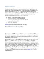
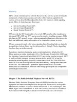
Figure 4-1
shows how many pages the ITU-T SS7 specifications contained in each
year. In 1980, there were a total of 320 pages, in 1984 a total of 641 pages, in 1988
a total of 1900 pages, and in 1999 approximately 9000 pages.
Figure 4-1. How Many Pages the ITU C7 Specifications Covered Based on Year
(Source: ITU [Modified])
[View full size image]
The following section introduces the SS7 network architecture.
< Day Day Up >
< Day Day Up >
SS7 Network Architecture
SS7 can employ different types of signaling network structures. The choice
between these different structures can be influenced by factors such as
administrative aspects and the structure of the telecommunication network to be
served by the signaling system.
The worldwide signaling network has two functionally independent levels:
• International
• National
This structure makes possible a clear division of responsibility for signaling
network management. It also lets numbering plans of SS7 nodes belonging to the
international network and the different national networks be independent of one
another.
SS7 network nodes are called signaling points (SPs). Each SP is addressed by an
integer called a point code (PC). The international network uses a 14-bit PC. The
national networks also use a 14-bit PC—except North America and China, which
use an incompatible 24-bit PC, and Japan, which uses a 16-
b
it PC. The national PC
is unique only within a particular operator's national network. International PCs are
unique only within the international network. Other operator networks (if they
exist) within a country also could have the same PC and also might share the same
PC as that used on the international network. Therefore, additional routing
information is provided so that the PC can be interpreted correctly—that is, as an
international network, as its own national network, or as another operator's national
network. The structure of point codes is described in Chapter 7
, "Message Transfer
Part 3 (MTP3)."
S
i
g
nalin
g
Links and Linksets
SPs are connected to each other by signaling links over which signaling takes
p
lace. The bandwidth of a signaling link is normally 64 kilobits per second (kbps).
Because of legacy reasons, however, some links in North America might have an
effective rate of 56 kbps. In recent years, high-speed links have been introduced
that use an entire 1.544 Mbps T1 carrier for signaling. Links are typically
engineered to carry only 25 to 40 percent of their capacity so that in case of a
failure, one link can carry the load of two.
To provide more bandwidth and/or for redundancy, up to 16 links between two SPs
can be used. Links between two SPs are logically grouped for administrative and
load-sharing reasons. A logical group of links between two SP is called a linkset.
Figure 4-2
shows four links in a linkset.
Figure 4-2. Four Links in a Linkset Between SPs
A number of linksets that may be used to reach a particular destination can be
grouped logically to form a combined linkset. For each combined linkset that an
individual linkset is a member of, it may be assigned different priority levels
relative to other linksets in each combined linkset.
A group of links within a linkset that have the same characteristics (data rate,
terrestrial/satellite, and so on) are called a link group. Normally the links in a
linkset have the same characteristics, so the term link group can be synonymous
with linkset.
R
outes and Routesets
SS7 routes are statically provisioned at each SP. There are no mechanisms for
route discovery. A route is defined as a preprovisioned path between source and
destination for a particular relation. Figure 4-3
shows a route from SP A to SP C.
Figure 4-3. Route from SP A to SP C
All the preprovisioned routes to a particular SP destination are called the routeset.
Figure 4-4
shows a routeset for SSP C consisting of two routes.
Figure 4-4. Routeset from SP A to SP C
The following section discusses the SP types.
N
ode T
y
pes
There are three different types of SP (that is, SS7 node):
• Signal Transfer Point
• Service Switching Point
• Service Control Point
Figure 4-5
graphically represents these nodes.
Figure 4-5. SS7 Node Types
The SPs differ in the functions that they perform, as described in the following
sections.
Signal Transfer Point
A Signal Transfer Point (STP) is responsible for the transfer of SS7 messages
between other SS7 nodes, acting somewhat like a router in an IP network.
An STP is neither the ultimate source nor the destination for most signaling
messages. Generally, messages are received on one signaling link and are
transferred out another. The only messages that are not simply transferred are
related to network management and global title translation. These two functions
are discussed more in Chapters 7
and 9. STPs route each incoming message to an
outgoing signaling link based on routing information contained in the SS7
message. Specifically, this is the information found in the MTP3 routing label, as
described in Chapter 7
.
Additionally, standalone STPs often can screen SS7 messages, acting as a firewall.
Such usage is described in Chapter 15
, "SS7/C7 Security and Monitoring."
An STP can exist in one of two forms:
• Standalone STP
• Integrated STP (SP with STP)
Standalone STPs are normally deployed in "mated" pairs for the purposes of
redundancy. Under normal operation, the mated pair shares the load. If one of the
STPs fails or isolation occurs because of signaling link failure, the other STP takes
the full load until the problem with its mate has been rectified.
Integrated STPs combine the functionality of an SSP and an STP. They are both
the source and destination for MTP user traffic. They also can transfer incoming
messages to other nodes.
Service Switching Point
A Service Switching Point (SSP) is a voice switch that incorporates SS7
functionality. It processes voice-band traffic (voice, fax, modem, and so forth) and
p
erforms SS7 signaling. All switches with SS7 functionality are considered SSPs
regardless of whether they are local switches (known in North America as an end
office) or tandem switches.
An SSP can originate and terminate messages, but it cannot transfer them. If a
message is received with a point code that does not match the point code of the
receiving SSP, the message is discarded.
Service Control Point
A Service Control Point (SCP) acts as an interface between telecommunications
databases and the SS7 network. Telephone companies and other
telecommunication service providers employ a number of databases that can be
queried for service data for the provision of services. Typically the request
(commonly called a query) originates at an SSP. A popular example is freephone
calling (known as toll-free in North America). The SCP provides the routing
number (translates the toll-free number to a routable number) to the SSP to allow
the call to be completed. For more information, see Chapter 11
, "Intelligent
N
etworks (IN)."
SCPs form the means to provide the core functionality of cellular networks, which
is subscriber mobility. Certain cellular databases (called registers) are used to keep
track of the subscriber's location so that incoming calls may be delivered. Other
telecommunication databases include those used for calling card validation (access
card, credit card), calling name display (CNAM), and LNP.
SCPs used for large revenue-generating services are usually deployed in pairs and
are geographically separated for redundancy. Unless there is a failure, the load is
typically shared between two mated SCPs. If failure occurs in one of the SCPs, the
other one should be able to take the load of both until normal operation resumes.
Queries/responses are normally routed through the mated pair of STPs that services
that particular SCP, particularly in North America.
See Chapters 10
, "Transaction Capabilities Application Part (TCAP)," and 11,
"Intelligent Networks (IN)," for more information on the use of SCPs within both
fixed-line and cellular networks. See Chapters 12
, "Cellular Networks," and 13,
"GSM and ANSI-41 Mobile Application Part (MAP)," for specific information on
the use of SCPs within cellular networks.
The following section introduces the concept of link types.
L
ink T
y
pes
Signaling links can be referenced differently depending on where they are in the
network. Although different references can be used, you should understand that the
link's physical characteristics remain the same. The references to link types A
through E are applicable only where standalone STPs are present, so the references
are more applicable to the North American market.
Six different link references exist:
• Access links (A links)
• Crossover links (C links)
• Bridge links (B links)
• Diagonal links (D links)
• Extended links (E links)
• Fully associated links (F links)
The following sections cover each link reference in more detail.
N
OTE
In the figures in the sections covering the different link references, dotted lines
represent the actual link being discussed, and solid lines add network infrastructure
to provide necessary context for the discussion.
Access Links (A Links)
Access links (A links), shown in Figure 4-6
, provide access to the network. They
connect "outer" SPs (SSPs or SCPs) to the STP backbone. A links connect SSPs
and SCPs to their serving STP or STP mated pair.
Figure 4-6. A Links
Cross Links (C Links)
Cross links (C links), shown in Figure 4-7
, are used to connect two STPs to form a
mated pair—that is, a pair linked such that if one fails, the other takes the load of
both.
Figure 4-7. C Links
C links are used to carry MTP user traffic only when no other route is available to
reach an intended destination. Under normal conditions, they are used only to carry
network management messages.
Bridge Links (B Links)
Bridge links (B links) are used to connect mated pairs of STPs to each other across
different regions within a network at the same hierarchical level. These links help
form the backbone of the SS7 network. B links are normally deployed in link quad
configuration between mated pairs for redundancy.
Figure 4-8 shows two sets of mated pairs of B links.
Figure 4-8. B Links
Diagonal Links (D Links)
Diagonal links (D links), shown in Figure 4-9
, are the same as B links in that they
connect mated STP pairs.
Figure 4-9. D Links
[View full size image]
The difference is that they connect mated STP pairs that belong to different
hierarchical levels or to different networks altogether. For example, they may
connect an interexchange carrier (IXC) STP pair to a local exchange carrier (LEC)
STP pair or a cellular regional STP pair to a cellular metro STP pair.
As mentioned, B and D links differ in that D links refer specifically to links that
are used either between different networks and/or hierarchical levels, as shown in
Figure 4-10
.
Figure 4-10. Existence of an STP Backbone and STP Hierarchy
[View full size image]
Extended Links (E Links)
Extended links (E links), shown in Figure 4-11
, connect SSPs and SCPs to an STP
p
air, as with A links, except that the pair they connect to is not the normal home
p
air. Instead, E links connect to a nonhome STP pair. They are also called alternate
access (AA) links. E links are used to provide additional reliability or, in some
cases, to offload signaling traffic from the home STP pair in high-traffic corridors.
For example, an SSP serving national government agencies or emergency services
might use E links to provide additional alternate routing because of the criticality
of service.
Figure 4-11. E Links
Fully-Associated Links (F Links)
Fully-associated links (F links), shown in Figure 4-12
, are used to connect network
SSPs and/or SCPs directly to each other without using STPs. The most common
application of this type of link is in metropolitan areas. F links can establish direct
connectivity between all switches in the area for trunk signaling and Custom Local
Area Signaling Service (CLASS), or to their corresponding SCPs.
Figure 4-12. F Links
Figure 4-13
shows an SS7 network segment. In reality, there would be several
factors more SSPs than STPs.
Figure 4-13. SS7 Network Segment
S
i
g
nalin
g
Modes
The signaling relationship that exists between two communicating SS7 nodes is
called the signaling mode. The two modes of signaling are associated signaling and
quasi-associated signaling. When the destination of an SS7 message is directly
connected by a linkset, the associated signaling mode is being used. In other
words, the source and destination nodes are directly connected by a single linkset.
When the message must pass over two or more linksets and through an
intermediate node, the quasi-associated mode of signaling is being used.
It's easier to understand the signaling mode if you examine the relationship of the
p
oint codes between the source and destination node. When using the associated
mode of signaling, the Destination Point Code (DPC) of a message being sent
matches the PC of the node at the far end of the linkset, usually referred to as the
far-end PC or adjacent PC. When quasi-associated signaling is used, the DPC does
not match the PC at the far end of the connected linkset. Quasi-associated signaling
requires the use of an STP as the intermediate node because an SSP cannot transfer
messages.
In Figure 4-14
, the signaling relationships between each of the nodes are as
follows:
• SSP A to SSP B uses quasi-associated signaling.
• SSP B to SSP C uses associated signaling.
• STP 1 and STP 2 use associated signaling to SSP A, SSP B, and each other.
Figure 4-14. SS7 Signaling Modes
As you can see from Figure 4-14
, associated signaling is used between nodes that
are directly connected by a single linkset, and quasi-associated signaling is used
when an intermediate node is used. Notice that SSP C is only connected to SSP B
using an F link. It is not connected to any other SS7 nodes in the figure.
When discussing the signaling mode in relation to the voice trunks shown between
the SSPs, the signaling and voice trunks follow the same path when associated
signaling is used. They take separate paths when quasi-associated signaling is used.
You can see from Figure 4-14
that the signaling between SSP B and SSP C follows
the same path (associated mode) as the voice trunks, while the signaling between
SSP A and SSP B does not follow the same path as the voice trunks.
S
i
g
nalin
g
Network Structure
Standalone STPs are prevalent in North America because they are used in this
region to form the backbone of the SS7 network. Attached to this backbone are the
SSPs and SCPs. Each SSP and SCP is assigned a "home pair" of STPs that it is
directly connected to. The network of STPs can be considered an overlay onto the
telecommunications network—a packet-switched data communications network
that acts as the nervous system of the telecommunications network. Figure 4-15
shows a typical example of how SSPs are interconnected with the STP network in
N
orth America.
Figure 4-15. Typical Example of North American SSP Interconnections
STPs are not as common outside North America. Standalone STPs typically are
used only between network operators and/or for applications involving the transfer
of noncircuit-related signaling. In these regions, most SSPs have direct signaling
link connections to other SSPs to which they have direct trunk connections. Figure
4-16 shows an example of this type of network with most SSPs directly connected
by signaling links.
Figure 4-16. Typical Example of SSP Interconnections in Most Areas Outside
North America
SSPs often have indirect physical connections to STPs, made through other SSPs
in the network. These are usually implemented as nailed-up connections, such as
through a Digital Access Cross-Connect System or other means of establishing a
semipermanent connection. Logically, these SSPs are directly connected to the
STP. The signaling link occupies a digital time slot on the same physical medium
as the circuit-switched traffic. The SSPs that provide physical interconnection
between other SSPs and an STP do not "transfer" messages as an STP function.
They only provide physical connectivity of the signaling links between T1/E1
carriers to reach the STP. Figure 4-17
shows an example of a network with no STP
connection, direct connections, and nondirect connections. SSP 1 is directly
connected to an STP pair. SSP 4 uses direct signaling links to SSP 2 and SSP 3,
where it also has direct trunks. It has no STP connection at all. SSP 2 and SSP 3
are connected to the STP pair via nailed-up connections at SSP 1.
Figure 4-17. Example of Direct and Indirect SSP Interconnections to STPs
[View full size image]
N
ormally within networks that do not use STPs, circui
t
-related (call-related)
signaling takes the same path through the network as user traffic because there is
no physical need to take a different route. This mode of operation is called
associated signaling and is prevalent outside North America. Referring back to
Figure 4-14
, both the user traffic and the signaling take the same path between SSP
B and SSP C.
Because standalone STPs are used to form the SS7 backbone within North
America, and standalone STPs do not support user traffic switching, the SSP's
signaling mode is usually quasi-associated, as illustrated between SSP A and SSP
B in Figure 4-14
.
In certain circumstances, the SSP uses associated signaling within North America.
A great deal of signaling traffic might exist between two SSPs, so it might make
more sense to place a signaling link directly between them rather than to force all
signaling through an STP.