Signaling System No.7 Protocol Architecture And Sevices part 11 doc
Bạn đang xem bản rút gọn của tài liệu. Xem và tải ngay bản đầy đủ của tài liệu tại đây (51.68 KB, 9 trang )
Summary
SS7 is a data communications network that acts as the nervous system to bring the
components of telecommunications networks to life. It acts as a platform for
various services described throughout this book. SS7 nodes are called signaling
p
oints (SPs), of which there are three types:
• Service Switching Point (SSP)
• Service Control Point (SCP)
• Signal Transfer Point (STP)
SSPs provide the SS7 functionality of a switch. STPs may be either standalone or
integrated STPs (SSP and STP) and are used to transfer signaling messages. SCPs
interface the SS7 network to query telecommunication databases, allowing service
logic and additional routing information to be obtained to execute services.
SPs are connected to each other using signaling links. Signaling links are logically
grouped into a linkset. Links may be referenced as A through F links, depending
on where they are in the network.
Signaling is transferred using the packet-switching facilities afforded by SS7.
These packets are called signal units (SUs). The Message Transfer Part (MTP) and
the Signaling Connection Control Part (SCCP) provide the transfer protocols. MTP
is used to reliably transport messages between nodes, and SCCP is used for
noncircuit-related signaling (typically, transactions with SCPs). The ISDN User
Part (ISUP) is used to set up and tear down both ordinary (analog subscriber) and
ISDN calls. The Transaction Capabilities Application Part (TCAP) allows
applications to communicate with each other using agreed-upon data components
and manages transactions.
< Day Day Up >
< Day Day Up >
Chapter 5. The Public Switched Telephone Network (PSTN)
The term Public Switched Telephone Network (PSTN) describes the various
equipment and interconnecting facilities that provide phone service to the public.
The network continues to evolve with the introduction of new technologies. The
PSTN began in the United States in 1878 with a manual mechanical switchboard
that connected different parties and allowed them to carry on a conversation.
Today, the PSTN is a network of computers and other electronic equipment that
converts speech into digital data and provides a multitude of sophisticated phone
features, data services, and mobile wireless access.
TIP
PSTN voice facilities transport speech or voice-
b
and data (such as fax/modems and
digital data), which is data that has been modulated to voice frequencies.
At the core of the PSTN are digital switches. The term "switch" describes the
ability to cross-connect a phone line with many other phone lines and switching
from one connection to another. The PSTN is well known for providing reliable
communications to its subscribers. The phrase "five nines reliability," representing
network availability of 99.999 percent for PSTN equipment, has become
ubiquitous within the telecommunications industry.
This chapter provides a fundamental view of how the PSTN works, particularly in
the areas of signaling and digital switching. SS7 provides control signaling for the
PSTN, so you should understand the PSTN infrastructure to fully appreciate how it
affects signaling and switching. This chapter is divided into the following sections:
• Network Topology
• PSTN Hierarchy
• Access and Transmission Facilities
• Network Timing
• The Central Office
• Integration of SS7 into the PSTN
• Evolving the PSTN to the Next Generation
We conclude with a summary of the PTSN infrastructure and its continuing
evolution.
< Day Day Up >
< Day Day Up >
Network Topology
The topology of a network describes the various network nodes and how they
interconnect. Regulatory policies play a major role in exactly how voice network
topologies are defined in each country, but general similarities exist. While
topologies in competitive markets represent an interconnection of networks owned
by different service providers, monopolistic markets are generally an
interconnection of switches owned by the same operator.
Depending on geographical region, PSTN nodes are sometimes referred to by
different names. The three node types we discuss in this chapter include:
• End Office (EO)— Also called a Local Exchange. The End Office provides
network access for the subscriber. It is located at the bottom of the network
hierarchy.
• Tandem— Connects EOs together, providing an aggregation point for traffic
between them. In some cases, the Tandem node provides the EO access to
the next hierarchical level of the network.
• Transit— Provides an interface to another hierarchical network level. Transit
switches are generally used to aggregate traffic that is carried across long
geographical distances.
There are two primary methods of connecting switching nodes. The first approach
is a mesh topology, in which all nodes are interconnected. This approach does not
scale well when you must connect a large number of nodes. You must connect
each new node to every existing node. This approach does have its merits,
however; it simplifies routing traffic between nodes and avoids bottlenecks by
involving only those switches that are in direct communication with each other.
The second approach is a hierarchical tree in which nodes are aggregated as the
hierarchy traverses from the subscriber access points to the top of the tree. PSTN
networks use a combination of these two methods, which are largely driven by cost
and the traffic patterns between exchanges.
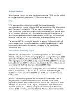
Figure 5-1
shows a generic PSTN hierarchy, in which End Offices are connected
locally and through tandem switches. Transit switches provide further aggregation
p
oints for connecting multiple tandems between different networks. While actual
network topologies vary, most follow some variation of this basic pattern.
Figure 5-1. Generic PSTN Hierarchies
[View full size image]
< Day Day Up >
< Day Day Up >
PSTN Hierarchy
The PSTN hierarchy is implemented differently in the United States and the United
Kingdom. The following sections provide an overview of the PSTN hierarchy and
its related terminology in each of these countries.
P
STN Hierarch
y
in the United States
In the United States, the PSTN is generally divided into three categories:
• Local Exchange Networks
• InterExchange Networks
• International Networks
Local Exchange Carriers (LECs) operate Local Exchange networks, while
InterExchange Carriers (IXCs) operate InterExchange and International networks.
The PSTN hierarchy in the United States is also influenced by market deregulation,
which has allowed service providers to compete for business and by the divestiture
of Bell.
Local Exchange Network
The Local Exchange network consists of the digital switching nodes (EOs) that
p
rovide network access to the subscriber. The Local Exchange terminates both
lines and trunks, providing the subscriber access to the PSTN.
A Tandem Office often connects End Offices within a local area, but they can also
be connected directly. In the United States, Tandem Offices are usually designated
as either Local Tandem (LT) or Access Tandem (AT). The primary purpose of a
Local Tandem is to provide interconnection between End Offices in a localized
geographic region. An Access Tandem provides interconnection between local End
Offices and serves as a primary point of access for IXCs. Trunks are the facilities
that connect all of the offices, thereby transporting inter-nodal traffic.
InterExchange Network
The InterExchange network is comprised of digital switching nodes that provide
the connection between Local Exchange networks. Because they are points of high
traffic aggregation and they cover larger geographical distances, high-speed
transports are typically used between transit switches. In the deregulated U.S.
market, transit switches are usually referred to as carrier switches. In the U.S.,
IXCs access the Local Exchange network at designated points, referred to as a
Point of Presence (POP). POPs can be connections at the Access Tandem, or direct
connections to the End Office.
International Network
The International network consists of digital switching nodes, which are located in
each country and act as international gateways to destinations outside of their
respective countries. These gateways adhere to the ITU international standards to
ensure interoperability between national networks. The international switch also
p
erforms the protocol conversions between national and international signaling.
The gateway also performs PCM conversions between A-law and -law to
p
roduce compatible speech encoding between networks, when necessary.
Service Providers
Deregulation policies in the United States have allowed network operators to
compete for business, first in the long-distance market (InterExchange and
International) beginning in the mid 1980s, and later in the local market in the mid
1990s. As previously mentioned, LECs operate Local Exchange networks, while
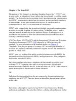
IXCs operate the long-distance networks. Figure 5-2
shows a typical arrangement
of LEC-owned EOs and tandems interconnected to IXC-owned transit switches.
The IXC switches provide long-haul transport between Local Exchange networks,
and international connections through International gateway switches.
Figure 5-2. Generic U.S. Hierarchies
[View full size image]
Over the last several years, the terms ILEC and CLEC have emerged within the
Local Exchange market to differentiate between the Incumbent LECs (ILECS) and
the Competitive LECs (CLECS). ILECs are the incumbents, who own existing
access lines to residences and corporate facilities; CLECs are new entrants into the
Local Exchange market. Most of the ILECs in the United States came about with
the divestiture of AT&T into the seven Regional Bell Operating Companies
(RBOC). The remainder belonged to Independent Operating Companies (IOCs).
Most of these post-divestiture companies have been significantly transformed
today by mergers and acquisitions in the competitive market. New companies have
experienced difficulty entering into the Local Exchange market, which is
dominated by ILECs. The ILECs own the wire to the subscriber's home, often
called the "last mile" wiring. Last mile wiring is expensive to install and gives the
ILECs tremendous market leverage. The long-distance market has been easier for
new entrants because it does not require an investment in last mile wiring.
Pre-Divestiture Bell System Hierarchy
Vestiges of terminology relating to network topology remain in use today from the
N
orth American Bell System's hierarchy, as it existe
d
prior to divestiture in 1984.
Telephone switching offices are often still referred to by class. For example, an EO
is commonly called a class 5 office, and an AT is called a class 4 office. Before
divestiture, each layer of the network hierarchy was assigned a class number.
Prior to divestiture, offices were categorized by class number, with class 1 being
the highest office category and class 5 being the lowest (nearest to subscriber
access). Aggregation of transit phone traffic moved from the class 5 office up
through the class 1 office. Each class of traffic aggregation points contained a
smaller number of offices. Table 5-1
lists the class categories and office types used
in the Bell System Hierarchy.
Table 5-1. Pre-Divestiture Class Categories and Office Types
Class Office Type
1 Regional Center
2 Sectional Center
3 Primary Center
4 Toll Center
5 End Office
Local calls remained within class 5 offices, while a cross-country call traversed the
hierarchy up to a regional switching center. This system no longer exists, but we
included it to give relevance to the class terminology, which the industry still uses
often.
P
STN Hierarch
y
in the United Kin
g
dom
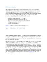
Figure 5-3
shows the PSTN topology used in the United Kingdom. End Offices are
referred to as Digital Local Exchanges (DLE). A fully meshed tandem network of
Digital Main Switching Units (DMSU) connects the DLEs. Digital International
Switching Centers (DISC) connect the DMSU tandem switches for international
call connections.
Figure 5-3. U.K. PSTN Hierarchy