Signaling System No.7 Protocol Architecture And Sevices part 14 potx
Bạn đang xem bản rút gọn của tài liệu. Xem và tải ngay bản đầy đủ của tài liệu tại đây (57.23 KB, 9 trang )
Integration of SS7 into the PSTN
This section provides a brief overview of how the SS7 architecture is applied to the
PSTN. Since SS7 has not been presented in great detail, the examples and
information are brief and discussed only in the context of the network nodes
p
resented in this section.
The PSTN existed long before SS7. The network's general structure was already in
p
lace, and it represented a substantial investment. The performance requirements
mandated by the 800 portability act of 1993 was one of the primary drivers for the
initial deployment of SS7 by ILECs in the United States. IXCs embraced SS7 early
to cut down on post-dial delay which translated into significant savings on
access/egress charges. Federal regulation, cost savings, and the opportunity to
p
rovide new revenue generating services created a need to deploy SS7 into the
existing PSTN.
SS7 was designed to integrate easily into the existing PSTN, to preserve the
investment and provide minimal disruption to the network. During SS7's initial
deployment, additional hardware was added and digital switches received software
upgrades to add SS7 capability to existing PSTN nodes. In the SS7 network, a
digital switch with SS7 capabilities is referred to as a Service Switching Point
(SSP). When looking at the SS7 network topologies in later chapters, it is
important to realize that the SSP is not a new node in the network.
Instead, it describes an existing switching node, to which SS7 capabilities have
been added. Similarly, SS7 did not introduce new facilities for signaling links, but
used timeslots on existing trunk facilities. PSTN diagrams containing End Offices
and tandems connected by trunks represent the same physical facilities as those of
SS7 diagrams that show SSP nodes with interconnecting links. The introduction of
SS7 added new nodes, such as the STP and SCP; however, all of the switching
nodes and facilities that existed before SS7 was introduced are still in place. Figure
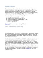
5-12 shows a simple view of the PSTN, overlaid with SS7-associated signaling
capabilities.
Figure 5-12. SS7 Overlaid onto the PSTN
[View full size image]
View a in the previous figure shows that trunk facilities provide the path for voice
and in-band signaling. View b shows the SS7 topology using simple associated
signaling for all nodes. View c shows the actual SS7-enabled PSTN topology. The
existing switching nodes and facilities are enhanced to provide basic SS7 call
p
rocessing functionality. Although this associated signaling architecture is still
quite common in Europe, the United States primarily uses a quasi-associated
signaling architecture.
S
S7 Link Inter
f
ace
The most common method for deploying SS7 links is for each link to occupy a
timeslot, such as a T1 or E1, on a digital trunk. As shown in Figure 5-12
, the
signaling links actually travel on the digital trunk transmission medium throughout
the network. At each node, the SS7 interface equipment must extract the link
timeslot from the digital trunk for processing. This process is typically performed
using a channel bank, or a Digital Access and Cross-Connect (DAC), which
demultiplexes the TDM timeslot from the digital trunk. The channel bank, or DAC,
can extract each of the timeslots from the digital stream, allowing them to be
p
rocessed individually. The individual SS7 link provides the SS7 messages
t
o the
digital switch for processing. While implementations vary, dedicated peripheral
p
rocessors usually process the lower levels of the SS7 protocol (Level 1, Level 2,
and possibly a portion of Level 3); call- and service-related information is passed
on to the central processor, or to other peripheral processors that are designed for
handling call processing–related messages. Of course, this process varies based on
the actual equipment vendor.
< Day Day Up >
< Day Day Up >
Evolving the PSTN to the Next Generation
The expansion of the Internet continues to drive multiple changes in the PSTN
environment. First, more network capacity is used to transport data over the PSTN.
Dial-up Internet services use data connections that are set up over the PSTN to
carry voice-band data over circuit-switched connections. This is a much different
situation than sending data over a data network. Data networks use packet
switching, in which many data transactions share the same facilities. Circuit-
switched connections are dedicated connections, which occupy a circuit for the
duration of a call. The phone networks were originally engineered for the three-
minute call, which was the average length used for calculations when engineering
the voice network. Of course, Internet connections tend to be much more lengthy,
meaning that more network capacity is needed. The changes driven by the Internet,
however, reach much further than simply an increase in network traffic. Phone
traffic is being moved to both private packet-based networks and the public
Internet, thereby providing an alternative to sending calls over the PSTN. Several
different architectures and protocols are competing in the VoIP market to establish
alternatives to the traditional circuit-switched network presented in this chapter.
The technologies are not necessarily exclusive; some solutions combine the
various technologies. Among the current leading VoIP technologies are:
• Soft switches
• H.323
• Session Initiation Protocol (SIP)
Each of these VoIP architectures use VoIP-PSTN gateways to provide some means
of communication between the traditional PSTN networks and VoIP networks.
These gateways provide access points for interconnecting the two networks,
thereby creating a migration path from PSTN-based phone service to VoIP phone
service. The core network interface connections for VoIP into the PSTN are the
trunk facilities that carry the voice channels and the signaling links that carry SS7
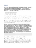
signaling. PRI is also commonly used for business to network access. Figure 5-13
shows the interconnection of VoIP architectures to the PSTN using signaling
gateways and trunking gateways. Chapter 14
, "SS7 in the Converged World,"
discusses these VoIP technologies in more detail.
Figure 5-13. VoIP Gateways to the PSTN
[View full size image]
< Day Day Up >
< Day Day Up >
Summary
This chapter provides an overview of the PSTN, as it existed before VoIP
technologies emerged. The majority of the PSTN still appears as this chapter
p
resents it. Many of the diagrams in telecommunications literature illustrating next
generation technologies—such as soft switches, H.323, and Session Initial Protocol
(SIP)—show interfaces to the PSTN. The diagrams refer to the PSTN discussed
here, dominated by large, digital switches. The technologies introduced often
replace some portion of the existing PSTN; however, they must also remain
connected to the existing PSTN to communicate with the rest of the world. The
VoIP-PSTN gateways provide this transition point, thus enabling a migration path
from the traditional PSTN to the next generation architecture.
While the PSTN varies in its implementation from country to country, a number of
common denominators exist. The PSTN is a collection of digital switching nodes
that are interconnected by trunks. The network topology is usually a hierarchical
structure, but it often incorporates some degree of mesh topology. The topology
p
rovides network access to residential and business subscribers for voice and data
services. VoIP began another evolution of the PSTN architecture. The PSTN is a
large infrastructure that will likely take some time to completely migrate to the
next generation of technologies; but this migration process is underway.
< Day Day Up >
< Day Day Up >
Chapter 6. Message Transfer Part 2 (MTP2)
This chapter is the first in a series of chapters that examine a specific SS7/C7
p
rotocol layer. This chapter details the Layer 2 protocol, which is known as
Message Transfer Part 2 (MTP2). MTP2 corresponds to OSI Layer 2 (the data link
layer) and as such is the lowest protocol in the stack. Sitting on the physical layer,
it provides a reliable means of transfer for signaling information between two
directly connected signaling points (SPs), ensuring that the signaling information is
delivered in sequence and error-free.
MTP2 performs the following functions:
• Delimitation of signal units
• Alignment of signal units
• Signaling link error detection
• Signaling link error correction by retransmission
• Signaling link initial alignment
• Error monitoring and reporting
• Link flow control
The signaling information is transmitted in frames called signal units (SUs). SUs
are of variable length, thereby requiring the start and end of each SU to be flagged
in the data stream. MTP2 performs this function, which is called signal unit
delimitation. The ability to correctly recognize signal units is achieved through
signal unit alignment.
Error correction is implemented by retransmitting the signal unit(s) received in
error. The link is also continuously monitored to ensure that error rates are within
p
ermissible limits. If the error rate becomes greater than predefined limits, MTP2
reports the failure to Message Transfer Part 3 (MTP3), which subsequently orders
MTP2 to remove the link from service. Conversely, initial alignment procedures
are used to bring links into service.
Link flow control procedures are provided to resolve congestion at the MTP2
layer. Congestion occurs if MTP3 falls behind in processing SUs from the MTP2
buffer.
This chapter describes each of the previously outlined functional areas of MTP2.
It is important to understand that the MTP2 protocol does not work end to end.
Rather, it operates on a link-by-link basis (known in datacoms as point to point)
between two SPs. Therefore, each signaling data link has an associated MTP2 at
each end.
< Day Day Up >
< Day Day Up >
Signal Unit Formats
SUs transfer information, which originates from higher layers (MTP3, ISUP,
SCCP, TUP, and so on) in the form of messages, over the signaling link. MTP2 is
similar to data network bit-oriented link protocols such as HDLC, SDLC, and
LAPB. The primary difference with these protocols comes from the performance
requirements in terms of lost and out-of-sequence messages and delay.
There are three types of SUs, each with its own format: the fill-in signal unit
(FISU), the link status signal unit (LSSU), and the Message Signal Unit (MSU).
An in-service signaling link carries a continuous SU stream in each direction.
FISUs and LSSUs are used only for MTP2 functions. MSUs also contain the same
MTP2 fields, but they have two additional fields filled with information from
MTP3 and Level 4 users that contain the real signaling content. This chapter
describes the MTP2 fields and the functions they perform. It begins by presenting
the three SU formats.
N
OTE
The formats shown are for 64-kbps links. The formats for high-speed (1.5/2.0
Mbps) signaling links might differ slightly in that the sequence number might be
extended to 12 bits. More details are available in Annex A of ITU-T Q.703 [51
].
Fill-In Signal Units
FISUs are the most basic SU and carry only MTP2 information. They are sent
when there are no LSSUs or MSUs to be sent, when the signaling link would
otherwise be idle. Sending FISUs ensures 100 percent link occupancy by SUs at all
times. A cyclic redundancy check (CRC) checksum is calculated for each FISU,
allowing both signaling points at either end of the link to continuously check
signaling link quality. This check allows faulty links to be identified quickly and
taken out of service so that traffic can be shifted to alternative links, thereby
helping meet the SS7/C7 network's high availability requirement. Because MTP2
is a point-to-point protocol, only the MTP2 level of adjacent signaling points
exchanges FISUs.
The seven fields that comprise a FISU, shown in Figure 6-1
, are also common to
LSSUs and MSUs. MTP2 adds the fields at the originating signaling point and
p
rocesses and removes them at the destination signaling point (an adjacent node).
Figure 6-1. FISU Format
L
ink Status Si
g
nal Units
LSSUs carry one or two octets of link status information between signaling points
at either end of a link. The link status controls link alignment, indicates the link's
status, and indicates a signaling point's status to the remote signaling point. The
p
resence of LSSUs at any time other than during link alignment indicates a faul
t
—
such as a remote processor outage or an unacceptably high bit error rate affecting
the ability to carry traffic.
The timers associated with a particular status indication govern the transmission
interval. After the fault is cleared, the transmission of LSSUs ceases, and normal
traffic flow can continue. As with FISUs, only MTP2 of adjacent signaling points
exchanges LSSUs. LSSUs are identical to FISUs, except that they contain an
additional field called the Status field (SF). Figure 6-2
shows the eight fields that
comprise an LSSU.
Figure 6-2. LSSU Format
Currently only a single-octet SF is used, even though the specifications allow for a
two-octet SF. From the single octet, only the first 3 bits are defined. These bits
p
rovide the status indications shown in Table 6-1.
Table 6-1. Values in the Status Field
C B A Status Indication Acronym Meaning
0 0 0 O: Out of Alignment SIO Link not aligned; attempting
alignment
0 0 1 N: Normal Alignment SIN Link is aligned
0 1 0 E: Emergency
Alignment
SIE Link is aligned
0 1 1 OS: Out of Service SIOS Link out of service; alignment
failure
1 0 0 PO: Processor Outage SIPO MTP2 cannot reach MTP3
1 0 1 B: Busy SIB MTP2 congestion
M
essa
g
e Si
g
nal Units
As shown in Figure 6-3
, MSUs contain the common fields of the FISU and two
additional fields: the Signaling Information Field (SIF) and the Service
Information Octet (SIO). MSUs carry the signaling information (or messages)
between both MTP3 and Level 4 users. The messages include all call control,
database query, and response messages. In addition, MSUs carry MTP3 network
management messages. All messages are placed in the SIF of the MSU.
Figure 6-3. MSU Format
[View full size image]
M
TP2 Overhead
Figure 6-4
shows an MSU. The MTP2 overhead is exactly the same for both
LSSUs and FISUs, except that an LSSU has an SF.
Figure 6-4. Fields Created and Processed by MTP2
Field Descriptions
Table 6-2
details the fields that are found inside the signal units. MTP2 exclusively
p
rocesses all fields except the SIO and the SIF.
Table 6-2. Field Descriptions
Field Length
in Bits
Description
Flag 8 A pattern of 011111110 to indicate the start and end of an SU.
BSN 7 Backward sequence number. Identifies the last correctly
received SU.
BIB 1 Backward indicator bit. Toggled to indicate an error with the
received SU.
FSN 7 Forward sequence number. Identifies each transmitted SU.
FIB 1 Forward indicator bit. Toggled to indicate the retransmission of
an SU that was received in error by the remote SP.
LI 6 Length indicator. Indicates how many octets reside between
itself and the CRC field. The LI field also implies the type of
signal unit. LI = 0 for FISUs, LI = 1 or 2 for LSSUs, and LI >2
for MSUs.
SF 8 to 16 Status field. Provides status messages in the LSSU only.
CK 16 Check bits. Uses CRC-16 to detect transmission errors.
SIO 8 Service Information Octet. Specifies which MTP3 user has
placed a message in the SIF.
SIF 16 to
2176
Signaling Information Field. Contains the "real" signaling
content. The SIF is also related to call control, network
management, or databases query/response.