Signaling System No.7 Protocol Architecture And Sevices part 16 pps
Bạn đang xem bản rút gọn của tài liệu. Xem và tải ngay bản đầy đủ của tài liệu tại đây (49.38 KB, 12 trang )
Signaling Link Initial
Alignment
The purpose of the
signaling link alignment
p
rocedure is to establish
SU timing and
alignment so that the
SPs on either side of the
link know where SUs
begin and end. In doing
so, you must inherently
test a link's quality
before putting it into
use. Example L-1
in
Appendix L
shows a
trace file of two aligned
SPs.
The signaling link
alignment procedure
ensures that both ends
have managed to
correctly recognize flags
in the data stream.
Initial alignment is
p
erformed for both
initial activation of the
link (power on) to bring
it to service and to
restore a link following
a failure. Alignment is
based on the compelled
exchange of status
information and a
p
roving period to ensure
that SUs are framed
correctly. MTP3
requests initial
alignment, which is
p
erformed by MTP2.
Because MTP2 operates
independently on each
link, the initial
alignment procedure is
p
erformed on a single
link without involving
other links. There are
two forms of alignment
p
rocedures: the
emergency procedure
and the normal
alignment procedure.
The emergency
p
rocedure is used when
the link being aligned is
the only available link
for any of the routes
defined within the SSP.
Otherwise, the normal
alignment procedure is
used.
S
tatus Indications
LSSUs are exchanged as
p
art of the alignment
p
rocedure. There are six
different status
indications, as shown
earlier in Table 6-1
.
Only the first four
indications are
employed during the
initial alignment
p
rocedure.
The alignment
p
rocedure passes
through a number of
states during the initial
alignment:
• Idle
• Not Aligned
• Aligned
• Proving
• Aligned/Ready
• In Service
Idle
When an SP is powered
up, the links are initially
p
ut in the idle state. The
idle state is the first state
entered in the alignment
p
rocedure; it indicates
that the procedure is
suspended. If the
p
rocedure fails at any
time, it returns to the
idle state. Timer T17
(MTP3) prevents the
rapid oscillation from in
service to out of service.
Timer T17 is started
when the link begins the
alignment procedure. No
further alignment
attempts are accepted
from a remote or local
SP until T17 has
expired. LSSUs of SIOS
(out of service) are sent
during the idle state.
LSSUs of this type are
sent continuously until
the link is powered
down or until an order to
b
egin initial alignment is
received from MTP3.
The FIB and the BIB of
the LSSUs are set to 1,
and the FSN and BSN
are set to 127.
N
ot Aligned
When MTP2 receives an
order to begin initial
alignment, the SP
changes the status of the
transmitted LSSUs to
indication SIO (out of
alignment) and starts the
timer T2. If T2 expires,
the status of the
transmitted LSSUs
reverts to SIOS.
Aligned
During T2 SIO, if SIN
(normal alignment) or
SIE (emergency
alignment) is received
from the remote SP, T2
is stopped, and the
transmission of SIO
ceases. The SP then
transmits SIN or SIE,
depending on whether
normal or emergency
alignment has been
selected and timer T3 is
started. The link is now
aligned, indicating that it
can detect flags and
signal units without
error. If T3 expires, the
alignment process
begins again,
transmitting LSSUs with
a status field of SIOS.
The aligned state
indicates that the link is
aligned and can detect
flags and signal units
without error.
Proving
Timer T4 governs the
p
roving period, and the
Alignment Error Rate
Monitor (AERM) is
used during this period.
The proving period is
used to test the signaling
link's integrity. FISUs
are sent and errors (CRC
and signaling unit
acceptance) are counted
during the proving
p
eriod. LSSUs are also
sent, indicating whether
this is a SIN or SIE
alignment.
The proving period is
shorter for emergency
alignment and as a result
is not as thorough. As
p
reviously stated,
emergency alignment is
selected if only one in
service (or none) exists
between two SPs. If the
local SP detects an
emergency alignment
situation, emergency
alignment is used
regardless of whether an
SIN or SIE is received
from the distant SP.
Similarly, emergency
alignment is used if an
SIE is received from the
distant SP, even when
the local MTP3 indicates
a normal alignment
situation (more than one
in-service link between
the two adjacent nodes).
If four errors are
detected during the
p
roving period, the link
is returned to state 00
(idle), and the procedure
begins again.
Aligned/Ready
When T4 expires, the
transmission of SIN/SIE
ceases, timer T1 is
started, and FISUs are
transmitted. If timer T1
expires, the transmission
of FISUs ceases, and
LSSUs of type SIOS are
transmitted.
In Service
Timer T1 stops upon
receiving either FISUs
or MSUs. When it stops,
the SUERM becomes
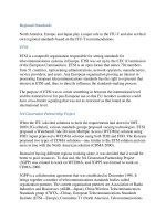
active. Figure 6-11
shows the initial
alignment procedure.
Figure 6-11. Procedure
for Signaling Link
Alignment
[View full size image]
< Day Day Up >
< Day Day Up >
Signaling Link Error Monitoring
Error rate monitoring is performed both for an in-service link and when the initial
alignment procedure is performed. Signal Unit Error Rate Monitor (SUERM) and
the Alignment Error Rate Monitor (AERM) are the two link error rate monitors
that are used [51
]. The SUERM performs monitoring when the link is in service,
and the AERM performs monitoring when the link is undergoing initial alignment
to bring it into service. The following sections describe these two link error rate
monitors.
S
UER
M
The SUERM is active when a link is in service, and it ensures the removal of a link
that has excessive errors. It employs a leaky bucket counter, which is initially set to
0. The counter is increased by 1 for each SU that is received in error. The counter
is decreased by 1 for each block of D consecutive SUs received without error, if it
is not at 0. If the link reaches a threshold of T, MTP2 informs MTP3, which
removes it from service. For a 64-kbps link, the values of D and T are 256 and 64,
respectively.
N
OTE
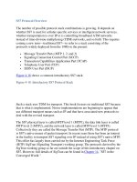
In ANSI networks, high-speed links (1.536 Mbps) use an errored interval monitor,
which differs in its threshold and counting values from those used by the SUERM
on low-speed links (see Figure 6-13
). Refer to ANSI T1.111 for more information.
Figure 6-13. SUERM Counter
The SUERM enters octet counting mode if an SU fails the acceptance procedure
(seven or more consecutive 1s, length is not a multiple of 8 bits, or SU length is not
between 6 and 279 octets). For every block of N octets counted during octet
counting mode, the SUERM is increased by 1. If the octet counting mode
continues for a significant period of time (meaning that SUs cannot be identified
from the received data), the link is removed from service. The SUERM reverts to
normal mode if a correctly checked SU is received.
A
ER
M
The AERM is active when the link is in the proving period of the initial alignment
p
rocedure. The counter is initialized to 0 at the start of the proving period and is
increased for every LSSU that is received in error. If octet counting mode is
entered during the proving period, the counter is increased for every block of N
octets that is counted. The proving period is aborted if the counter reaches a
threshold value of T
i
; it is reentered upon receiving a correct LSSU, or upon the
expiration of the aborted proving period. Different threshold values T
in
and T
ie
are
used for the normal and emergency alignment procedures, respectively. If the
p
roving is aborted M times, the link is removed from service and enters the idle
state.
The values of the four parameters for 64-kbps and lower bit rates (both for ITU and
ANSI) are as follows:
• T
in
= 4
• T
ie
= 1
• M = 5
• N = 16
< Day Day Up >
< Day Day Up >
Processor Outage
The processor outage condition occurs when SUs cannot be transferred to MTP3 or
above. This could be the result of a central processing failure or communication
loss between MTP2 and Levels 3/4 when a distributed processing architecture is
used. A processor outage condition won't necessarily affect all signaling links in an
SP, nor does it exclude the possibility that MTP3 can control the operation of the
signaling link. When MTP2 recognizes a local processor outage condition, it
transmits LSSUs with the status field set to status indication processor outage
(SIPO) and discards any MSUs it has received. When the distant SP receives the
SIPO status LSSU, it notifies its MTP3 and begins to continuously transmit FISUs.
N
ote that the affected links remain in the aligned state.
< Day Day Up >
< Day Day Up >
Flow Control
Flow control allows incoming traffic to be throttled when the MTP2 receive buffer
becomes congested. When an SP detects that the number of received MSUs in its
input buffer exceeds a particular value—for example, because MTP3 has fallen
behind in processing these MSUs—it begins sending out LSSUs with the status
indicator set to busy (SIB). These LSSUs are transmitted at an interval set by timer
T5, sending SIB (80 to 120 ms), until the congestion abates. The congested SP
continues sending outgoing MSUs and FISUs but discards incoming MSUs. It also
"freezes" the value of BSN and the BIB in the SUs it sends out to the values that
were last transmitted in an SU before the congestion was recognized. This
acknowledgment delay would normally cause timer T7, excessive delay of
acknowledgment, at the distant SP to time out; however, timer T7 restarts each
time an SIB is received. Therefore, timer T7 does not time out as long as the
distant SP receives SIBs.
Timer T6, remote congestion, is started when the initial SIB is received. If timer
T6 expires, it is considered a fault, and the link is removed from service. Timer T6
ensures that the link does not remain in the congested state for an excessive period
of time.
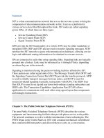
When congestion abates, acknowledgments of all incoming MSUs are resumed,
and periodic transmission of the SIB indication is discontinued. When the distant
SP receives an SU that contains a negative or positive acknowledgment whose
backward sequence number acknowledges an MSU in the RTB, timer T6 is
stopped, and normal operation at both ends ensues. Figure 6-14
depicts flow
control using LSSUs with status indication busy.
Figure 6-14. Flow Control Using Status Indication SIB
N
OTE
The mechanism for detecting the onset of congestion is implementation-specific
and should be chosen to minimize the oscillation between the onset and abatement
of congestion.