Signaling System No.7 Protocol Architecture And Sevices part 17 pot
Bạn đang xem bản rút gọn của tài liệu. Xem và tải ngay bản đầy đủ của tài liệu tại đây (44.64 KB, 5 trang )
Message Format
The MTP3 portion of an SS7 message consists of two fields: the Signaling
Information Field (SIF) and the Service Information Octet (SIO). The SIF contains
routing information and the actual payload data being transported by the MTP3
service. The SIO contains general message characteristics for identifying the
network type, prioritizing messages (ANSI only), and delivering them to the
appropriate MTP3 user. When an SS7 node receives messages, Signaling Message
Handling (SMH) uses the SIO and the portion of the SIF that contains routing
information to perform discrimination, routing, and distribution. SMH functions
are discussed in the "Signaling Message Handling
" section, later in this chapter.
S
ervice In
f
ormation Octet
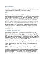
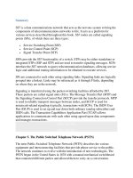
As shown in Figure 7-4
, the SIO is a one-octet field composed of the Service
Indicator (SI) and the Subservice Field (SSF). While the SI occupies the four least
significant bits of the SIO, the SSF occupies the four most significant bits.
Figure 7-4. SIO Fields
The Service Indicator designates the type of MTP payload contained in the
Signaling Information Field. MTP3 uses the SI to deliver the message payload to
the appropriate MTP3 user, using the message distribution function discussed later
in the "Signaling Message Handling
" section. The message is delivered to MTP3
for SI values of 0–2; the message is delivered to the appropriate User Part for SI
values of 3 and higher. For example, all ISUP messages used in setting up phone
calls would use a Service Indicator of 5. Table 7-1
lists the values for the Service
Indicator.
Table 7-1. Service Indicator Values
Binary
Value
Type of Payload
0000 Signaling Network Management Messages
0001 Signaling Network Testing and Maintenance Messages
0010 Signaling Network Testing and Maintenance Special Messages
(ANSI) or Spare (ITU-T)
0011 SCCP
0100 Telephone User Part
0101 ISDN User Part
0110 Data User Part (call and circuit-related messages)
0111 Data User Part (facility registration and cancellation messages)
1000 Reserved for MTP Testing User Part
1001 Broadband ISDN User Part
1010 Satellite ISDN User Part
1011 –
1111
Spare
[*]
[*]
ANSI reserves values 1101 and 1110 for individual network use.
The SSF consists of two fields: the Network Indicator (NI) and Priority. The
p
riority field is defined for ANSI networks and is an option that may be
implemented in ITU-T national networks. The priority bits are spare bits in ITU-T
networks when not used for Priority. The NI indicates whether the message is for a
national or international network. A national network can also discriminate
between different Point Code structures used by different countries and invoke the
appropriate version of the message handling functions accordingly. Table 7-2
lists
the values for the NI.
Table 7-2. Network Indicator Values
Binary Value Message Type
0000 International
0001 International Spare
0010 National
0011 National Spare
Messages are usually routed using the national or international values. The spare
values are often used for testing and for temporary use during Point Code
conversions. The national spare value can also be used for creating an additional
national network. For example, in some European countries, network operators
have used the national spare network indicator for creating a national interconnect
network. Using this method, the switches between operator networks have two
Point Codes assigned: one for the interconnect network using the national network
indicator, and the other for the operator network using the national spare network
indicator. This allows the network operator to administer Point Codes as he
chooses within his national network, while using the interconnect network to
interface with other network operators.
The ITU-T defines the two least significant bits of the SSF as spare bits. These bits
are used to define message priority in ANSI networks, but are unused in ITU-T
networks. The ANSI message priority values are 0–3 with 3 being the highest
p
riority. The node originating the message assigns the priority to allow message
throttling during periods of network congestion. The use of the message priority
field is discussed in the section, "Multiple Congestion Levels
."
S
i
g
nalin
g
In
f
ormation Field (SIF)
The SIF contains the actual user data being transported by MTP, such as telephone
numbers, control signals, or maintenance messages. The Service Indicator
designates the type of information contained within the SIF user data field. For
example, a Service Indicator of 0 indicates that the SIF contains Signaling Network
Maintenance data. A Service Indicator of 5 indicates that the SIF contains ISUP
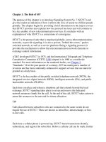
information. The beginning portion of the SIF also contains the Routing Label that
is used for routing the message within the network. The Routing Label contains the
following three components:
• Originating Point Code (OPC)— Identifies the node originating the message
• Destination Point Code (DPC)— Identifies the destination node
• Signaling Link Selector (SLS)— An identifier used for load sharing across
linksets and links
Figure 7-5
shows the fields in the routing label.
Figure 7-5. Routing Label Fields
When a node generates a message, it inserts its own Point Code into the OPC field.
This Point Code identifies the node that originated the message to subsequent
nodes. As previously discussed, the DPC field is populated based on the internal
routing tables. The SLS code is used for load sharing MTP3 User Part messages
across links and linksets. The originating node generates a bit pattern and places it
in this field. The SLS code maps the message to a particular link among the
linksets and links that are available for routing. It is generated in a manner that
minimizes mis-sequencing of messages belonging to a particular transaction from
the perspective of MTP users, while balancing the load across the links and
linksets.
For more information about the use of the SLS code for load sharing, see
"Routing
" within the "Signaling Message Handling" section. The Signaling Link
Code (SLC) for messages generated by MTP3 (e.g., SNM) replaces the SLS field.
The "Message Load Sharing
" section discusses the SLC code further.
The ITU-T and ANSI Routing Labels are similar in structure, but differ slightly in
size and meaning. The following sections detail these differences.
ITU-T Routing Label
The ITU-T routing label consists of the following fields:
• DPC
• OPC
• SLS
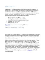
The ITU-T point codes are 14 bits in length. For ITU-T national networks, all 14
bits are interpreted as a single identifier that is often referred to as a structureless
Point Code. For international networks, an International Signaling Point Code
(ISPC) is subdivided into hierarchical fields, shown in Figure 7-6
.
Figure 7-6. ITU-T Routing Label
The SLS is a four-bit field that identifies the link and/or linkset on which a
message is transmitted.
ANSI Routing Label
The ANSI routing label consists of the following fields:
• DPC
• OPC
• SLS
The ANSI Point Code is 24 bits in length and is subdivided into three fields of one
octet each, as shown in Figure 7-7
. The three octets define the network, cluster,
and member that uniquely identify the signaling node within the network
hierarchy. The SLS field is an eight-bit field used for selecting the link and/or
linkset for message transmission. This field was only five bits in earlier versions of
the protocol, but was extended for better load sharing across signaling links in the
1996 version of the ANSI standards.
Figure 7-7. ANSI Routing Label