Signaling System No.7 Protocol Architecture And Sevices part 19 ppsx
Bạn đang xem bản rút gọn của tài liệu. Xem và tải ngay bản đầy đủ của tài liệu tại đây (96.48 KB, 25 trang )
Signaling Network Management
Failures in the SS7 network have potentially devastating effects on the
communications infrastructure. The loss of all SS7 signaling capabilities at an SP
isolates it from the rest of the network. The SS7 networks in existence today are
known for their reliability, primarily due to the robustness of the SS7 protocol in
the area of network management. Of course, this reliability must be accompanied
by good network design to provide sufficient network capacity and redundancy.
MTP3 Network Management is comprised of a set of messages and procedures
that are used to ensure a healthy signaling transport infrastructure. This involves
automatically invoking actions based on network events, such as link or route
failures and reporting network status to other nodes.
Signaling Network Management is divided into three processes:
• Traffic management
• Route management
• Link management
Traffic management is responsible for dealing with signaling traffic, which are the
messages generated by MTP3 users, such as ISUP and SCCP. The goal of Traffic
management is to keep traffic moving toward its destination, even in the event of
network failures and congestion, with as little message loss or mis-sequencing as
p
ossible. This movement often involves rerouting traffic onto an alternate network
p
ath and, in some situations, might require message retransmission.
Route management exchanges information about routing status between nodes. As
events occur that affect route availability, route management sends messages to
notify other nodes about the change in routing states. Route management supplies
information to traffic management, allowing it to adjust traffic patterns and flow
accordingly.
Link management activates, deactivates, and restores signaling links. This involves
notifying MTP users of the availability of signaling links and invoking procedures
to restore service when a disruption has occurred. This level of network
management is most closely associated with the physical hardware.
A number of timers are involved in all of these network management procedures.
Timers are used to ensure that actions occur when they should. Without timers,
network management procedures could halt at certain points and it would take
forever for an event to happen. For example, when a message is transmitted, timers
are often started to ensure that a response is received within a specified period of
time.
The following section discusses a number of the timers used for Signaling Network
Management. It enhances the description of the procedure but is not intended to be
a complete reference for every timer used. A complete list of timers can be found
in Appendix G
, "MTP Timers in ITU-T/ETSI/ANSI Applications."
N
etwork Mana
g
ement Messa
g
es (H0/H1 Codes)
All network management messages contain a routing label and an identifier known
as an H0/H1 code. Additional message fields are often included based on the
p
articular message type. The general format of a Network Management message is
shown in Figure 7-15
.
Figure 7-15. Basic Network Management Message
The "H0/H1" codes, or "Heading" codes, are simply the message type identifiers.
There are two Heading Codes for each message: H0 for the family of messages,
and H1 for the specific message type within the family. Table 7-4
lists the H0/H1
codes for each message type. The family (H0 code) is listed on the left of the chart.
All messages in a row belong to the same message family. For example, the H0/H1
code for a COA message is 12 and it belongs to the CHM (Changeover Message)
family. Appendix A
, "MTP Messages (ANSI/ETSI/ITU)," provides the full
message name and description for each message entry in Table 7-4
.
Table 7-4. H0/H1 Codes
Message
Group
H
1
H
0
0 1 2 3 4 5 6 7 8
0
Changeov
er (CHM)
1 COO COA CB
D
CBA
Emergenc
y
Changeov
er (ECM)
2 ECO ECA
Flow
Control
(FCM|
3 RCT TFC
Transfer
(TFM)
4 TFP TCP
[*
]
TFR TCR
[
*]
TF
A
TCA
[
*]
Routeset
Test
(RSM)
5 RST
RSP
[*]
RSR RCP
[
*]
RCR
[
*]
Manageme
nt
Inhibiting
(MIM)
6 LIN LUN LIA LUA LID LFU LLT/LLI
[*]
LRT/LRI
[*]
Traffic
(TRM)
7 TWR
A
TRW
[
*]
Data Link
(DLM)
8 DLC CSS CNS CNP
9
User Part
Flow
Control
(UFC)
A UPU
[*]
ANSI only.
L
ink Mana
g
ement
Links are physical entities that are made available to MTP3 users when they have
p
roven worthy of carrying messages. If a link fails, it has a direct impact on the
two nodes the link connects. It is link management's responsibility to detect any
communication loss and attempt to restore it. Both nodes connected to the link
invoke procedures for restoration in an attempt to restore communication. Link
management can be divided into three processes:
• Activation
• Deactivation
• Restoration
Activation is the process of making a link available to carry MTP3 user traffic.
Maintenance personnel typically perform it by invoking commands from an OAM
interface to request that the link be activated for use. When a link is aligned at level
2 and passes the proving period, the link is declared available to traffic
management.
Deactivation removes a link from service, making it unavailable for carrying
traffic. Like activation, this process is typically initiated by invoking commands
from an OAM interface. The link is declared unavailable to traffic management
when it is deactivated.
Restoration is an automated attempt to restore the link to service after a failure,
making it available for traffic management use. The link alignment procedure is
initiated when level 2 has detected a link failure. When the link is aligned and has
p
assed the proving period, a signaling link test is performed. After the signaling
link test has successfully completed, traffic management makes the link available
for use.
Signaling Link Test Control
When a signaling link is activated, it must undergo initial alignment at MTP2.
After a successful initial alignment, the link performs a signaling link test initiated
by the Signaling Link Test Control (SLTC) function.
SLTC messages are identified by MTP3 with a Service Indicator of 1 or 2. An SI
of 1 indicates a Signaling Network Test message and is used for ITU-T networks.
An SI of 2 indicates a Signaling Network Test Special message and is used in
ANSI networks. SLTC messages follow the same message structure as Signaling
N
etwork Management messages; they use a Heading code, which immediately
follows the Routing Label. Table 7-5 shows the H0 and H1 field values.
Table 7-5. H0 and H1 Field Values
Message Group
H1
H0 0 1 2
0
SLT 1 SLTM SLTA
MTP3 sends an SLTM (Signaling Link Test Message) over the link with the node's
DPC at the far end of the linkset. The SLC code in the routing label identifies the
link on which the message is sent. The test is performed only if the SLC matches
the link on which the message is sent, and if the OPC in the routing label matches
the far end Point Code of the receiving node. The message's user data is a simple
test pattern of bytes and is typically user configurable. The receiving node
responds with a Signaling Link Test Acknowledgement (SLTA) containing the test
p
attern received in the SLTM message. The SLTA test pattern must match what
was sent in the SLTM or the test is considered a failure. In addition, the DPC,
network indicator, and SLC in the SLTM are checked to ensure that they match the
information at the node on the receiving end of the link over which the message
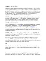
was sent. Figure 7-16
shows an example of an SLTM/SLTA exchange with a test
p
attern.
Figure 7-16. Signaling Link Test Control
The SLTC ensures that the two connected nodes can communicate at level 3 before
p
lacing a link into service for user traffic. At this point the SLTC can detect
p
roblems, such as an incorrectly provisioned Point Code or network indicator, in
link activation. If alignment or the signaling link test fails, the procedure is
restarted after a period of time designated by T17. In ANSI networks, a link failure
timer (T19) is used to guard the amount of time the link remains out of service.
Upon its expiration, a notification is raised to system maintenance, where the
restoration procedure can be restarted or the link can optionally be declared as
"failed" until manual intervention occurs.
Automatic Allocation of Signaling Terminals and Links
The SS7 standards provide specifications for the automatic allocation of both
signaling terminals and signaling links. The automatic allocation of signaling
terminals allows a pool of signaling terminals to exist that can be mapped to a
signaling link for use. The robustness of electronic circuitry today makes this
option of little value for most network operators. Redundancy for signaling
terminal hardware can be achieved in parallel with link redundancy using alternate
links. Link redundancy is a better choice because links are much more likely to fail
than signaling terminal hardware.
Automatic link allocation allows other digital circuits normally used to carry voice
to be allocated as signaling links, when needed. Automatic signaling terminal and
automatic link allocation are rarely used in networks.
R
oute Mana
g
ement
Signaling route management communicates the availability of routes between SS7
nodes. Failures such as the loss of a linkset affect the ability to route messages to
their intended destination. A failure can also affect more than just locally
connected nodes. For example, the linkset between STP1 and SSP B has failed in
Figure 7-17
. As a result, SSP A should only route messages to SSP B through
STP1 as a last resort because STP1 no longer has an associated route. Even though
none of the links belonging to SSP A have failed, its ability to route messages to
SSP B is affected. Signaling route management provides the means to
communicate these types of changes in route availability using Signaling Network
Management messages.
Figure 7-17. How Loss of Linkset Affects Routes
Route management uses the following messages to convey routing status to other
network nodes:
• Transfer Prohibited (TFP)
• Transfer Restricted (TFR)
• Transfer Allowed (TFA)
• Transfer Controlled (TFC)
The following additional messages are used for conveying the routing status of
clusters. They are only used in ANSI networks:
• Transfer Cluster Prohibited (TCP)
• Transfer Cluster Restricted (TCR)
Each node maintains a state for every destination route. As route management
messages are received, the state is updated based on the status conveyed by the
message. This allows nodes to make appropriate routing choices when sending
messages. Routes can have one of three different states:
• Allowed
• Prohibited
• Restricted
The following sections discuss each of these states and the messages and
p
rocedures that are associated with them.
As shown in Figure 7-18
, the messages used by route management all have a
common format consisting of a standard routing label, an H0/H1 code identifying
the type of network management message and a destination. The destination is the
Point Code of the node for which routing status is being conveyed.
Figure 7-18. Route Status Message Format
Transfer Restricted
The restricted state indicates a limited ability to route messages. This status
signifies that the primary route is unavailable and that another route should be
chosen, if it exists. If the restricted route is the last available route in a routeset, it
is still used for routing.
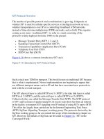
In Figure 7-19
, a linkset failure has occurred between SSP A and STP 2. The loss
of the linkset causes STP2 to change its routing status to restricted for SSP A. Note
that it can still route messages over the C-Link to STP1, destined for SSP A; this
makes the status restricted and not prohibited. In this case, the linkset from STP 2
to SSP A is an associated route and is ordinarily designated as the "primary" route,
while the linkset to STP 1 is a quasi-associated route and is therefore designated as
an "alternate," or secondary route to SSP A.
Figure 7-19. Transfer Restricted
The Transfer Restricted message is sent to adjacent nodes to notify them of the
restricted route. TFR is used in ANSI networks and is a national option in ITU
networks. As shown in Figure 7-18
, the TFR message contains the H0/H1 code,
which identifies it as a TFR message and the Point Code of the affected
destination.
Upon receiving a Transfer Restricted message, traffic management shifts traffic to
another route, provided that another route toward the affected destination is
available. In Figure 7-19
, when the TFR message is received at SSP B, traffic
management performs a controlled reroute is to switch traffic to the linkset
between SSP B and STP1. For a description of the controlled reroute procedure,
refer to the "Controlled Rerouting
" section. After receiving a Transfer Restricted
message, a Routeset Restricted message is sent periodically to test the status of the
routeset. The Routeset Restricted message asks the question, "Is the route still
restricted?" Refer to the "Routeset Test
" section for more information on testing
the routeset status.
Transfer Prohibited
The Transfer Prohibited state indicates a complete inability to route messages to
the affected destination. If one exists, another route must be chosen for routing. If
no route exists, traffic management is notified that it cannot route messages to the
destination.
In Figure 7-20
a linkset failure occurs, causing STP 1 to become isolated from SSP
B. Notice that there are no possible routes by which STP1 can reach SSP B. STP1
changes its routing status to "prohibited" concerning SSP B. A TFP message is sent
to convey the prohibited status to other nodes. There are two methods of sending
the TFP status:
• Broadcast method
• Response method
Figure 7-20. Transfer Prohibited
When the broadcast method is used, all adjacent nodes are immediately notified
about the prohibited route status. The response method does not send notification
until an attempt is made to reach the affected destination. The choice of which
method to use is often implemented as a provisioned option that can be set on the
signaling equipment. If the broadcast method is being used but for some reason a
node still receives an MSU for a prohibited destination, a TFP is still sent using the
response method. Figure 7-20
demonstrates the use of the broadcast method.
Figure 7-18
shows that the TFP message contains the H0/H1 code, identifying the
message as a TFP message and the Point Code of the affected destination.
When a TFP message is received, traffic management performs a forced reroute to
immediately route traffic over another route, if another route to the destination is
available. Refer to the section on "Forced Rerouting
" for a complete description of
forced rerouting. If an STP receives a TFP and the route on which it is received is
the last available route, the STP sends out TFP messages to its adjacent nodes to
indicate that it can no longer route to the affected destination.
Transfer Allowed
The transfer allowed state indicates that a route is available for carrying traffic.
This is the normal state for in-service routes. When a route has been in the
restricted or prohibited state and full routing capability is restored, the route's status
is returned to transfer allowed. The transfer allowed message is sent to convey the
new routing status to adjacent nodes. Figure 7-21
shows that the linkset between
SSP B and STP 1, along with the linkset between STP 1 and STP 2, has been
restored to service. STP 1 recognizes that it has regained full routing capability to
SSP B and sends a TFA message to its adjacent nodes to update their routing
status.
Figure 7-21. Transfer Allowed
Figure 7-18
shows that the TFA message contains the H0/H1 code, which
identifies the message as a TFA message and the Point Code of the affected
destination.
Routeset Test
Routeset Test is part of the Transfer Prohibited and Transfer Restricted procedures.
While Transfer Prohibited and Transfer Restricted convey the status of the
routeset, Routeset Test checks to ensure that the status is correct.
The Routeset Test message tests the state of a routeset when it is prohibited or
restricted. Each time a Routeset Test message is received, the status is compared to
the current status of the affected destination. If the states match, the message is
discarded and no further action is taken; otherwise, an appropriate message is sent
to update the status. The state testing is performed to ensure that both nodes are in
sync regarding the routing status. Figure 7-22
shows an example in which the
routeset for SSP A is prohibited at STP 1. If, for some reason, the STP sent a
Transfer Allowed message to the SSP for a previously prohibited routeset and the
SSP failed to receive the message, the STP would have a routeset marked as
Transfer Allowed and the SSP would think it was still Transfer Prohibited.
Figure 7-22. Routeset Test
The frequency with which the Routeset Test message is sent is based on timer T10.
Each time T10 expires, a Routeset Test message is sent to test the routeset status.
In Figure 7-22
, STP 1 has sent a TFP message to SSP B. SSP B responds by
sending Routeset Prohibited Test messages on a periodic basis.
The Routeset Test procedure is stopped when a TFA for the affected destination is
received.
Transfer Controlled
The Transfer Controlled message is used to indicate congestion for a route to a
p
articular destination. The TFC message implies "transmit" congestion, in contrast
to the "receive" buffer congestion handled by MTP2. Figure 7-23
shows a typical
example in which an STP receives messages from a number of nodes for the same
destination. This queues a large number of messages in the transmit buffer for the
destination, putting the destination route into a congested state. The STP sends a
TFC message to the SPs that generate the traffic, informing them that the STP 1
route to the destination is congested.
Figure 7-23. Transfer Controlled
In the international network and ITU-T networks that do not implement the option
of multiple congestion levels, the TFC simply indicates that the destination is in a
congested state. In ANSI networks, the TFC includes a congestion level to indicate
the severity of the congestion. The congestion level is used in conjunction with the
message priority level to throttle messages during periods of congestion. The TFC
message contains the H0/H1 code that identifies the message as a TFC message,
the Point Code of the affected destination, and the congestion status shown in
Figure 7-24
.
Figure 7-24. Transfer Controlled Message Format
Multiple Congestion Levels
Congestion levels are part of the Transfer Controlled message.
The ITU-T defines an option for national networks to allow the use of multiple
congestion levels to throttle traffic during periods of congestion. ANSI networks
implement this option. There are three levels of congestion, 1 being the lowest and
3 being the highest. A congestion level of 0 indicates no congestion. The
congestion levels represent the level of message queuing for a specific route.
Figure 7-25
demonstrates the use of the TFC using multiple congestion levels.
Figure 7-25. ANSI Routeset Congestion (National Multilevel)
When an STP receives a message for a congested routeset, the priority field in the
SIO is compared with the congestion level of the congested routeset. If the priority
of the message is lower than the congestion level, a TFC message is sent to the
message originator indicating the current congestion level. The originating node
updates the congestion status of the routeset and notifies its MTP users with an
MTP congestion primitive so they can take the appropriate action to reduce traffic
generation. The "MTP3/User Part Communication
" section discusses MTP
p
rimitives further.
To begin the Routeset Congestion Test procedure, timer T15 is started when the
TFC message is received. If timer T15 expires before receiving another TFC
message, an RCT message is sent to the congested destination. The RCT message
has its priority field set to a value of one less than the routeset's current congestion.
If the routeset congestion level at the STP remains the same, another TFC message
is sent in response to the RCT. Remember, any message with a lower priority than
the current congestion level invokes the TFC to be sent. If, however, the
congestion level has lowered, the RCT message is allowed to route to its
destination. The RCT message is simply discarded when it arrives at the
destination. Its only purpose is to test the path through the network.
Timer T16 is started when the RCT message is sent. If a TFC is not received
before the expiration of T16, another RCT message is sent with a message priority
one lower than the previous RCT. This cycle is repeated until the congestion level
reaches 0.
Routeset Congestion Test
The Routeset Congestion Test message tests the congestion level of a network
destination. It poses the question, "Is the Routeset still at congestion level x?"
As shown in Figure 7-18
, the RCT message contains the H0/H1 code that identifies
the message as a RCT message and the Point Code of the affected destination. As
discussed in the previous section, the RCT message is sent in response to a TFC.
The priority of the RCT message is set to one less than the congestion level
identified in the TFC message. The node sending the RCT can determine whether
to resume traffic transmission of a given priority based on whether a TFC is
received in response to the RCT. As shown in Figure 7-25
, if no TFC is received
within T16, the sending node marks the routeset with the new congestion evel,
which is based on the priority of the transmitted RCT message. Refer to section
"Multiple Congestion Levels
" for a complete discussion of how the RCT message
is used in the transfer controlled procedure.
Traffic Management
Traffic management is the nucleus of the MTP network management layer that
coordinates between the MTP users' communication needs and the available
routing resources. It is somewhat of a traffic cop in stopping, starting, redirecting,
and throttling traffic. Traffic is diverted away from unavailable links and linksets,
stopped in the case of unavailable routesets, and reduced where congestion exists.
Traffic management depends on the information provided by link management and
route management to direct user traffic. For example, when a TFP is received for a
destination, traffic management must determine whether an alternate route is
available and shift traffic to this alternate route. During this action, it determines
what messages the unavailable destination has not acknowledged so those
messages can be retransmitted on the alternate route. This section discusses the
following procedures that are employed by traffic management to accomplish such
tasks:
• Changeover
• Emergency changeover
• Time-controlled changeover
• Changeback
• Time-controlled diversion
• Forced rerouting
• Controlled rerouting
• MTP restart
• Management inhibiting
Changeover
Changeover is the process of diverting traffic to a new link when a link becomes
unavailable. When a link becomes unavailable and there are other links in the
linkset, traffic is "changed over" to one of the other links. If there are no other
available links in the linkset and another linkset is available, traffic is diverted to
the alternate linkset. The node at either end of the link can detect the failure, and it
is possible that both ends might detect it simultaneously. When the link is
determined to be unavailable, a Changeover Order (COO) message is sent to the
far end to initiate the changeover. The COO contains the SLC of the failed link and
the Forward Sequence Number (FSN) of the last accepted message. Figure 7-26
shows the format of the COO message.
Figure 7-26. Changeover Message Format
Each link contains a retransmission buffer that holds messages until they are
acknowledged. When the COO is received, the FSN is compared to the messages
in the retransmission buffer to determine which messages need to be retransmitted
because the far end has not received them. All messages received with a sequence
number higher than the FSN in the COO are retransmitted. The messages in the
transmission and retransmission buffer are diverted to the new signaling link for
transmission with the traffic that is normally destined for that link. The correct
message sequence for the retransmitted messages is maintained based on the SLS
values. The SLS values for new messages are mapped to the remaining available
signaling links so the new traffic being transmitted is no longer sent to the
unavailable link. A Changeover Acknowledgement (COA) is sent in response to a
Changeover order. The COA also contains the SLC of the failed link and the FSN
of the last accepted message. This allows the node receiving the COA to determine
where to begin retransmission of Signaling Units.
Both nodes connected to the link might receive notification from link management
and begin changeover at the same time, sending a COO simultaneously. If a COO
has been sent by one node and a COO is received for the same link, the changeover
p
roceeds using the received COO as an acknowledgement. The COA message is
still sent to acknowledge the changeover, but the changeover procedure does not
wait if it has already received a COO. Figure 7-27
shows SSP A with one link in
each linkset to STP 1 and STP 2. When the link to STP 2 fails, SSP A detects the
failure and performs a changeover to the STP 1 linkset. The changeover is made to
a new linkset because no other links are available in the same linkset. If more links
were available in the STP 2 linkset, the changeover would be to a new link in the
same linkset.
Figure 7-27. Changeover to a New Linkset
Emergency Changeover
It is possible that a node cannot determine the last acknowledged message when a
link fails. An example is the failure of the signaling terminal hardware. Typically,
the signaling terminal hardware contains the receive buffers and keeps track of the
FSN for incoming signaling units. There is no way to determine where the request
for retransmission should start if this information is lost. In this case, an
Emergency Changeover (ECO) is sent to the far end to initiate a changeover. The
ECO does not contain the last accepted FSN field because the last good message
cannot be determined. Figure 7-28
shows the format for the ECO message.
Figure 7-28. Emergency Changeover Message
Because there is no FSN to compare with the messages in the retransmission
buffer, buffer updating is not performed when the ECO is received. All traffic that
has not been transmitted is diverted to the new signaling link to be sent out with
the normal traffic for that link. This obviously increases the chances of message
loss as compared to a normal changeover; however, this is to be expected because
the recovery is from a more catastrophic failure.
Time-Controlled Changeover
There are times when a link might fail and no alternate path exists between the
nodes at each end of the link. Because a changeover message cannot be sent to
inform the far end, after a certain period of time the traffic is simply diverted over
an alternate path to the destination. Figure 7-29
shows an example of a Time-
Controlled Changeover at SSP A from the STP 2 linkset to the STP 1 linkset.
Figure 7-29. Time-Controlled Changeover
When this situation occurs, a timer (T1) is started and, when the timer expires,
traffic is sent on an alternate route. The time-controlled changeover procedure can
also be used in two other situations: for a processor outage, and when a link is put
into the inhibited state.
The SS7 standards do not fully specify the use of the time-controlled changeover
for a processor outage. When used for an inhibited link, traffic is simply diverted
to the alternate route at timer expiry, without a link failure.
Changeback
Changeback is the process of diverting traffic from an alternative signaling link
back to the link that is usually used.
When a link becomes unavailable, a changeover occurs, diverting traffic to another
link. When the link becomes available again, a changeback restores traffic to its
normal pattern. When link management declares the link available, transmission of
traffic over the alternative link is stopped and the traffic is stored in a changeback
buffer. A Changeback Declaration (CBD) message is sent over the alternate
signaling link; it indicates that all diverted traffic being sent over the alternate link
will now be sent over the normal link. A changeback code is assigned by the SP
p
erforming the changeback and is included in the CBD message. This allows a
specific changeback to be identified when multiple changebacks are happening in
p
arallel. When the CBD message is received, a Changeback Acknowledgement
(CBA) is sent in response. Both the CBD and CBA messages contain the H0/H1
code that identifies the message type and the changeback code, as shown in Figure
7-30.
Figure 7-30. Changeback Declaration Message
Time-Controlled Diversion
There are situations where a changeback should occur, but there is no way to signal
the changeback to the other end of the signaling link.
As shown in Figure 7-31
, the SSP A – STP 2 linkset that was unavailable has been
restored. Assuming that SSP A set its routing table to load share between STP 1
and STP 2 for traffic destined to SSP B, the MSUs previously diverted to STP 1
should now be sent to STP 2. If a path existed between STP 1 and STP 2, either
SSP A or STP 1 normally sends a CBD.
Figure 7-31. Time-Controlled Diversion
Although the path does not exist in this case, the need to divert the MSUs still
exists. After the link to STP 2 completes the MTP restart procedure, timer T3 is
started. At the expiration of T3, the normal traffic to STP 2 is restarted.
Forced Rerouting
Forced rerouting is used to divert traffic away from an unavailable route
immediately. This occurs in response to a TFP message. As previously discussed,
the TFP message is used to signal the inability to route to a particular destination.
When a route toward a destination signaling point has become unavailable, traffic
for that route is stopped and stored in a forced rerouting buffer. An alternative
route is then determined by searching for the route with the next highest priority in
the routeset. The diverted traffic is then transmitted over the alternative route,
along with the normal traffic flow for that route. The messages from the forced
rerouting buffer are sent out before any new traffic is diverted. If no alternative
route exists, the internal routeset state for the signaling point is changed to
p
rohibited to indicate that messages can no longer be sent to that destination. If the
node is an STP, it sends TFP messages out to its connected nodes to signal its
inability to reach the destination.
In Figure 7-32
, the route from STP 1 to SSP B has become unavailable, causing
STP 1 to send TFP concerning SSP B. SSP A contains two routes in the routeset
for SSP B: a route via STP 1, and another via STP 2. Traffic is diverted from the
STP 1 route to the STP 2 route. Receiving a TFP message always causes a Forced
Reroute, provided that there is another available route to which to shift traffic.
Figure 7-32. Forced Rerouting
Controlled Rerouting
Controlled rerouting is used in response to TFR and TFA messages. This
p
rocedure is mo
r
e "controlled" than forced rerouting in the sense that traffic is sent
over an available route and is shifted to another available route.
Forced rerouting is performed when messages must be shifted away from a route
that is no longer available. With controlled rerouting, transmission of traffic over
the linkset is stopped and stored in a controlled rerouting buffer, and timer T6 is
started. When timer T6 expires, traffic is restarted on the new linkset, beginning
with the transmission of messages stored in the controlled rerouting buffer. The use
of the timer helps prevent out-of-sequence messages by allowing traffic to
complete on the previous route before restarting on the new route.
In Figure 7-33
, SSP A receives a TFR from STP 1 for SSP B. SSP A has a routeset
for destination SSP B with two routes in the routeset. SSP A performs controlled
rerouting of traffic from STP 1 to STP 2. When the route from STP1 to SSP B is
restored, STP 1 sends a TFA to indicate that full routing capability toward SSP B
has been restored. SSP A performs controlled rerouting again, this time shifting
traffic from the STP 2 route to the STP 1 route using the same basic procedure.
Figure 7-33. Controlled Rerouting
MTP Restart
The MTP restart procedure was not a part of the early SS7 standards; it was added
later to address issues with nodes coming into service or recovering from SS7
outages. The newly in-service or recovering node deals with heavy SS7
management traffic and might have limited SS7 resources available initially. The
routing information the node maintains might also be stale from lack of
communication with the remainder of the network. The restart procedure provides
a dampening effect to the network management procedures that take place when a
node causes major changes in network status. This allows the node to stabilize and
bring sufficient SS7 links into service to handle the impending traffic.
The overall MTP restart procedure is handled using a restart timer (T20). If the
restart is occurring at an STP, an additional timer (T18) is used to divide the restart
into two phases. The MTP restart procedure begins when the first link of the
restarting MTP becomes available. Routing status updates (TFP, TFR) are then
received from adjacent nodes, followed by the TRA message that signals the end
of the updates. If the node is an STP, it will then broadcast its own routing status
updates. The TRA message is unique to the MTP restart procedure and is used to
signal that the routing status update is complete and traffic is now allowed. As
shown in Figure 7-15
, the TRA message contains the H0/H1 code that indicates a
TRA message.
The following lists summarize the procedures that take place during the MTP
restart for a SSP and a STP:
SSP MTP Restart
• First link comes into service.
• Start Timer T20.
• Update routing tables based on TFP, TFR, and TFA messages from adjacent
nodes. Each adjacent node sends TRA to signal the end of the routing
update.
• T20 is stopped or expired.
• Send TRA messages to all adjacent nodes.
• Notify local MTP users of the routing status of routesets maintained by the
node.
STP MTP Restart
• First link comes into service.
• Start Timer T18 and T20.
• Update routing tables based on TFP, TFR, and TFA messages from adjacent
nodes. Each adjacent node sends TRA to signal the end of the routing
update.
• T18 is stopped or expires.
• TFP and TFR messages are broadcast to all adjacent nodes for inaccessible
destinations.
• T20 is stopped or expires.
• Send TRA messages to all adjacent nodes.
• Notify local MTP users of the routing status of routesets maintained by the
node.
Figure 7-34
shows SSP A undergoing an MTP restart. Routing status is received
from adjacent nodes, followed by TRA messages. The expiration of timer T20
completes the restart. The SSP sends TRA messages to each of the connected STPs
and notifies the user parts of routing status.
Figure 7-34. MTP Restart
Management Inhibiting
Signaling link management inhibiting is used to prevent user traffic on the links
while leaving the links themselves in service. This process is useful for isolating
links for testing purposes.
Maintenance personnel typically initiate management inhibiting by issuing
commands via a maintenance interface to the SS7 equipment. When a link is
p
laced in the "inhibited" traffic state, only MTP3 maintenance and test messages
(Service Indicator 0–2) are permitted on the link. The actual state of the link from
the perspective of signaling link management does not change. Links can only be
inhibited if they do not cause any destinations (routesets) defined at the node to
become isolated. The link continues to transmit FISUs, MSUs, and LSSUs as
needed. The inhibit procedure uses the Link Inhibit (LIN) and Link Inhibit
Acknowledgement (LIA) messages to communicate between the two nodes
concerning the linkset being inhibited. These messages use the basic network
management format, as shown in Figure 7-15
.
Inhibiting
In Figure 7-35
, a maintenance engineer at STP 1 must perform testing on a link
that has had intermittent problems. The engineer issues the command at a
maintenance terminal to place the link in an inhibited state so it is not used by
normal user traffic. STP 1 sends a LIN message to SSP A. Because SSP A has
other links available for routing, it determines that it can safely remove the link
from traffic service and respond with an LIA back to STP 1 in acknowledgement.
Because SSP A has only 1 per linkset, it performs a controlled reroute of traffic to
STP 2 linkset.
Figure 7-35. Link Inhibit
Uninhibiting
When a link is in the inhibited state, an inhibit test message is periodically sent to
verify that the link is still in the inhibited state. Since an inhibited link is not
available for user traffic, the inhibit test is a safeguard to ensure that the link state
is correctly marked as inhibited at the far end of the link. Both the locally inhibited
node and the remote node perform the inhibit test. ITU-T and ANSI use the
following messages and timers to perform the inhibit test:
ITU-T
• Local Link Inhibit Test message (LLT)— T22
• Remote Link Inhibit Test message (LRT)— T23
ANSI
• Local Link Inhibit Test message (LLI)— T20
• Link Remote Inhibit Test message (LRI)— T21
Although the message acronyms chosen by ITU-T and ANSI are slightly different,
both network types use the same respective messages.
The node at which the link is locally inhibited sends a Link Local Inhibit Test
message at each Local Inhibit Test timer period (T20 or T22). The remote node
receiving the message checks the state at its end to ensure that it is still set as
"remotely inhibited." The remote end also sends a LRI message at each LRT timer
p
eriod (T21 or T23). The node at the locally inhibited link that receives the
message checks the state to ensure that it is still set as "locally inhibited." The
p
eriodic test continues between the nodes at each end of the link until the link is
uninhibited. Figure 7-36
shows an example of the link inhibit test between SSP A
and STP 1 where the link has been locally inhibited by SSP A. The example shows
an ANSI network; ITU-T and ANSI differ only in the message acronyms and timer
labels used.
Figure 7-36. Link Inhibit Test
The link uninhibit procedure does the reverse of the inhibit procedure: it puts the
link back into service for user traffic. The uninhibit procedure is invoked by
issuing commands at a maintenance interface to the SS7 equipment. The procedure
makes use of the LUN message to request that the link be uninhibited, and the
LUA message acknowledges the request.
In Figure 7-37
, the link from STP 1 to STP A is ready to return to use for user
traffic. A command is issued to "uninhibit" it at the maintenance position. The
command causes an LUN (Link Uninhibit) message to be sent from STP 1 to SSP
A, and SSP A responds with an LUA. Because each linkset contains only one link,
a controlled reroute shifts user traffic back to its original route using STP 1.
Figure 7-37. Link Uninhibit
Forced Uninhibiting
In the period during which a link is inhibited, the loss of other links can cause the
inhibited link to become a critical resource. The forced uninhibit or "Management-
initiated" uninhibit is a way for a node to request that an inhibited link be restored
to service for user traffic when no other links are available.
Forced uninhibiting uses the LFU (Link Forced Uninhibit) message to request that
the link be uninhibited. In Figure 7-38
, SSP A has inhibited the link from SSP A to
STP 1. The link from STP 1 to STP 2 now fails, which causes STP 1 to be isolated
from SSP A. STP 1 sends an LFU to SSP A to request that the link be uninhibited
for use by user traffic. SSP A sends an LUN to uninhibit the link. STP 1 now
responds with an LUA and user traffic can flow over the link.
Figure 7-38. Link Forced Uninhibit
M
TP3/User Part Communication
As shown in Figure 7-39
, MTP3 uses primitives to communicate with MTP users
about its routing status. A primitive is simply an indication that is passed between
levels of the protocol by the software implementing the SS7 software stack. The
p
rimitives indicate the ability or inability of MTP3 to route messages. Primitives
are not seen on the network because they are part of the MTP3 implementation at a
node; however, as with most of the network management procedures, primitives
are related to SS7 Network Management messages. As seen from the description o
f
the primitives, changing network conditions communicated by SNM messages
cause different primitives to be sent to the user parts.
• MTP-Transfer— Indicates the ability to transfer messages to a destination.
The transfer primitive is used to pass signaling message data between the
MTP3 users and the MTP3 Signaling Message Handling function. This is
the normal state for a destination when the network is healthy.
• MTP-Pause— Indicates the complete inability to transfer messages to a
particular destination. This primitive informs the MTP user that no messages
should be sent to the destination. When the destination is available again,
MTP3 sends an MTP-Resume. This indication is sent to the user part when a
TFP has been received for a destination.
• MTP-Resume— Indicates the ability to transfer messages to a previously
unavailable destination. This indication is sent to the user part when a TFA
is received and an MTP-Pause had previously been sent to the user part.
• MTP-Status— Indicates a partial routing ability. This is used to indicate the
congestion level to the user part in the case of multiple-level congestion. The
user part uses this information to prevent sending messages that have a
priority less than the reported congestion level. It can also be used to
indicate that a user part is unavailable.
Figure 7-39. MTP3/User Part Communication
S
i
g
nalin
g
Network Mana
g
ement Example
As noted throughout this chapter, traffic, route, and link management are coupled
in a modular fashion to form a complete network management system for SS7.
Here we examine a failure scenario to show how these cooperating components
depend on and communicate with each other.
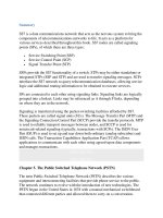
Figure 7-40
shows a typical failure scenario in an SS7 network. SSP A has two
linksets connecting it to the network, with one link in each linkset. This is a
common configuration for SSPs.
Figure 7-40. Signaling Network Management Failure Scenario
The single link within the linkset connecting SSP A to STP 2 is broken. This type
of problem often occurs when aggressive backhoe operators are digging near
b
uried communications spans. From the diagram, you can see all three of the major
SNM blocks at work. Link management detects that the link has failed and reports
this loss to both traffic management and route management. Next it begins link
restoration procedures by attempting to align the link. Recall from the chapter on
MTP2 that the alignment procedure sends out an LSSU of type SIOS (Status
Indication Out of Service), followed by SIO (Status Indication Out of Alignment).
This occurs at both SSP A and STP 2, and link management attempts to restore the
link at each node. Of course, with the broken link path, the alignment fails and the
p
rocess is repeated. Having received link management's notification of the loss of
the only direct link to STP 2, traffic management at SSP A performs a changeover
to the linkset to STP 1, sending a COO to STP 2. The COO contains the FSN of
the last MSU that was acknowledged on the link before it went down. STP 2 uses
this information to resend the messages from its retransmit buffer to SSP A via the
C-Link to STP 1, beginning with the "FSN + 1" sequence number. STP 2 sends a
COA to SSP A to acknowledge the COO message and performs a changeover on
its end. The COA contains the FSN of the last MSU acknowledged by STP 2. This
allows SSP A to determine the correct point to start retransmission of messages to
STP 2.
Both SSP A and STP 2 have now informed each other about where message
retransmission should start when traffic restarts on the alternate route. Route
management at STP 2 responds to the link management's notification by sending a
TFR for SSP A to all of its connected linksets, except for the linkset of its quasi-
associated route to SSP A. SSP B and SSP C perform controlled rerouting of traffic
destined for SSP A to their STP 1 linkset. They also respond to the TFR by
p
eriodically sending RSR based on the routeset test timer (T10). They repeat
sending the RSR every T10 until they receive a TFA. Route management at STP 2
sends a TFP message to STP 1 for SSP A. The loss of its direct route to SSP A
means that any messages it receives for SSP A must be routed over its quasi-
associated route via STP 1. The TFP is sent to STP 1 to prevent it from sending
any messages for SSP A; otherwise those messages would have to be sent back to
STP 1, causing unnecessary traffic over the C-Links and at STP 2, as well as a
p
otential loop routing.
The final result is that the route to SSP A over the STP2 linkset is now marked as
"restricted" at SSP B and C. They send all traffic destined for SSP A to STP 1,
unless they lose the linkset to STP 1. The loss of the STP1 linkset would leave the
restricted route through STP 2 as the only available path to SSP A, resulting in
messages being routed over the C-link from STP2 to STP1, and finally to SSP A.