Signaling System No.7 Protocol Architecture And Sevices part 44 ppt
Bạn đang xem bản rút gọn của tài liệu. Xem và tải ngay bản đầy đủ của tài liệu tại đây (63.42 KB, 13 trang )
Summary
The Intelligent Network is a continually-evolving model for distributed service
p
rocessing in the telecommunications network. The models that represent call
p
rocessing provide a generic interface for distributed control, thereby allowing
intelligence to move out of the SSP. The IN model also fits well into some next
generation telecom architectures, such as those built on IP-based softswitches.
There are standards for delivering TCAP over the IP transport, such as the Bellcore
GDI interface, which allows IN services to continue to work with little or no
modifications. Adjuncts already provide IP connections to IN SLPs, so the
migration path to IP-based IN networks is occurring. A common theme among the
p
roposed nex
t
-generation architectures is distribution of the functions performed
by switching exchanges. The IN model fits into this structure by providing a
generic framework for both extending the PSTN and allowing it to interwork with
the new architectures.
Of course, there are other intelligent endpoint architectures that provide
alternatives to the IN model, such as the Session Initiation Protocol (SIP). The
p
oint of this chapter is not to debate the merits of which architecture is best but to
p
rovide an understanding of the IN architecture, which so heavily depends on SS7
signaling to function.
< Day Day Up >
< Day Day Up >
Chapter 12. Cellular Networks
This chapter introduces Global System for Mobile communications (GSM), which
is the most popular digital cellular network standard in terms of architecture,
discusses interfaces and protocols, and concludes by presenting examples of
mobility management and call processing in the network. The protocols that are
found in GSM to perform these functions—namely, Base Station Subsystem
Application Part (BSSAP) and Mobile Application Part (MAP)—are applications
(subsystems) that utilize the underlying functionality of the SS7 protocols and
network. This chapter aims to provide enough background on GSM cellular
networks for you to understand the MAP that is used for mobility management and
call processing within the GSM network, which is discussed in Chapter 13
, "GSM
and ANSI-41 Mobile Application Part (MAP)."
The European Telecommunication Standard Institute (ETSI) formulated GSM.
Phase one of the GSM specifications was published in 1990, and the commercial
operation using the 900 Mhz range began in 1991. The same year, a derivative of
GSM, known as Digital Cellular System 1800 (DCS 1800), which translated GSM
to the 1800 Mhz range, appeared. The United States adapted DCS 1800 into the
1900 Mhz range and called it Personal Communication System 1900 (PCS 1900).
By 1993, 36 GSM networks existed in 22 countries [119
].
Pre-GSM cellular networks are analog and vary from country to country—for
example, the United States still uses Advanced/American Mobile Phone Service
(AMPS), and the UK used Total Access Communication System (TACS). With
these older analog standards, it was impossible to have one phone work in more
than one country. In addition, because of the analog nature of the speech, quality
could be relatively poor, and there were no provisions for supplementary services
(such as call waiting). Although it is standardized in Europe, GSM is not just a
European standard. At the time of this writing, there are more than 509 GSM
networks (including DCS 1800 and PCS 1900) operating in 182 countries around
the world, with 684.2 million subscribers [Source: GSM Association]. See
Appendix I
for a list of mobile networks by country.
GSM has been released in phases. The following are the features of these phases:
GSM Phase 1 (1992) Features
• Call Forwarding
• All Calls
• No Answer
• Engaged
• Unreachable
• Call Barring
• Outgoing—Bar certain outgoing calls
• Incoming—Bar certain incoming calls
• Global roaming—–If you visit any other country or parts in an existing
country with GSM, your cellular phone remains connected without having to
change your number or perform any action.
GSM Phase 2 (1995) Features
• Short Message Service (SMS)— Allows you to send and receive text
messages.
• Multiparty Calling— Talk to five other parties and yourself at the same time.
• Call Holding— Place a call on hold.
• Calling Line Identity Service— This facility allows you to see the incoming
caller's telephone number on your handset before answering.
• Advice of Charge— Allows you to keep track of call costs.
• Cell Broadcast— Allows you to subscribe to local news channels.
• Mobile Terminating Fax— Another number you are issued that can receive
faxes.
• Call Waiting— Notifies you of another call while you are on a call.
• Mobile Data Services— Allows handsets to communicate with computers.
• Mobile Fax Service— Allows handsets to send, retrieve, and receive faxes.
GSM Phase 2 + (1996) Features
• Upgrades and improvements to existing services; the majority of the upgrade
concerns data transmission, including bearer services and packet switched
data at 64 kbps and above
• DECT access to GSM
• PMR/Public Access Mobile Radio (PAMR)-like capabilities to GSM in the
local loop
• SIM enhancements
• Premium rate services
• Virtual Private Networks Packet Radio
Unlike Europe (and most of the world), which only pursued GSM for digital
cellular networks, North America has pursued a mix of TDMA (IS-54, IS-136),
CDMA, and GSM. At the time of this writing, TDMA and CDMA have been more
widely deployed in North America than GSM. However, this situation is rapidly
beginning to reverse with GSM continually gaining ground.
One benefit of 3G technology is that it unifies these diverse cellular standards.
Although three different air interface modes exist—wideband CDMA, CDMA
2000, and the Universal Wireless Communication (UWC-136) interfaces—each
should be able to work over both current GSM network architectures.
< Day Day Up >
< Day Day Up >
Network Architecture
GSM architecture can be divided into three broad functional areas: the Base
Station Subsystem (BSS), the Network and Switching Subsystems (NSS), and the
Operations Support Subsystem (OSS). Each of the subsystems is comprised of
functional entities that communicate through various interfaces using specified
p
rotocols. The "Interfaces and Protocols" section of this chapter overviews the
interfaces and SS7/C7 protocols that are used in the NSS and BSS.
Figure 12-1
shows a general GSM architecture to illustrate the scope and the
entities that comprise the three subsystems.
Figure 12-1. General GSM Architecture, Including the Three Main Separations in
the Network
The BSS is comprised of the Base Transceiver Station (BTS) and the Base Station
Controller (BSC). The BSS provides transmission paths between the Mobile
Stations (MSs) and the NSS, and manages the transmission paths. The NSS is the
brain of the entire GSM network and is comprised of the Mobile Switching Center
(MSC) and four intelligent network nodes known as the Home Location Register
(HLR), Visitor Location Register (VLR), Equipment Identity Register (EIR), and
the Authentication Center (AuC). The OSS consists of Operation and Maintenance
Centers (OMCs) that are used for remote and centralized operation, administration,
and maintenance (OAM) tasks. The OSS provides means for a service provider to
control and manage the network. The OSS is usually proprietary in nature and does
not have standardized interfaces (using SS7 is irrelevant). Therefore, it is not
considered. The BSS is the radio part, and this book does not detail radio related
signaling. Therefore, the focus is on the NSS where the MAP protocol is used.
GSM utilizes a cellular structure. Each cell is hexagonal in shape so that the cells
fit together tightly. Each cell is assigned a frequency range. The size of the cell is
relatively small so the scarce frequencies can be reused in other cells. Each cell
contains a base station, and a lot of planning goes into ensuring that base stations
from different cells do not interfere with each other. One disadvantage of small
cells is that the number of required base stations increases the infrastructure costs.
The primary difference between GSM 900 and the GSM 1800/1900 systems is the
air interface. In addition to using another frequency band, they both use a
microcellular structure. As shown in Figure 12-2
, this permits frequency reuse at
closer distances, thereby enabling increases in subscriber density. The
disadvantage is the higher attenuation of the air interface because of the higher
frequency.
Figure 12-2. Frequency Reuse and Cellular Structure
One interesting point is that cell sizes vary because each cell can only serve a finite
number of subscribers—typically 600 to 800. This means that cells become smaller
for higher population density areas.
If a mobile moves from one cell to another during an active call, it should be clear
that the call must be handed over to the new cell; this should be done in a fully
transparent fashion to the subscriber. This process is known as a handover. The
Mobile Switching Centre (MSC) monitors the strength of the incoming signal from
the cellular phone (known as MS). When the signal power drops below a certain
level, it indicates that the user might have entered another cell or is at the edge of
the current cell. The MSC then checks to see if another cell is receiving a stronger
cell. If it is, the call is transferred to that cell.
The approximate location of an MS, even if idle, has to be tracked to allow
incoming calls to be delivered.
N
OTE
Handovers and location tracking involve extensive and complex SS7/C7 signaling.
In a cellular network, most signaling relates to the support of roaming
functionality. Only a fraction of the signaling relates to call control.
The architecture that is presented in this section is not meant to be all-inclusive.
Rather, its purpose is to provide the reader with the basic knowledge to
comprehend SS7/C7 protocols that relate to cellular networks. When "GSM" is
stated, it includes DCS, PCS, and GPRS networks. The rest of this section
discusses the function of the components that comprise the NSS and BSS, along
with the cellular phone itself and the identifiers associated with it.
M
obile Station (MS)
GSM refers to the cellular handsets as MS. PCMIA cards are also available for
laptops to allow data transfer over the GSM network, without the need for a voice-
centric handset. The MS consists of the physical equipment that the subscriber uses
to access a PLMN and a removable smart card, known as the SIM, to identify the
subscriber.
GSM was unique to use the SIM card to break the subscriber ID apart from the
equipment ID. The SIM card is fully portable between Mobile Equipment (ME)
units. This allows many features that we take for granted, such as being able to
swap MS simply by swapping our SIM card over. All functionality continues
seamlessly, including billing, and the telephone number remains the same.
An MS has several associated identities, including the International Mobile
Equipment Identity (IMEI), the International Mobile Subscriber Identity (IMSI),
the Temporary Mobile Subscriber Identity (TMSI), and the Mobile Station ISDN
(MSISDN) number. The following sections examine each of these identities, in
turn, so that signaling sequences in which they are involved make sense.
IMEI
Each ME has a unique number, known as the IMEI, stored on it permanently. The
IMEI is not only a serial number; it also indicates the manufacturer, the country in
which it was produced, and the type approval. It is assigned at the factory.
GSM 03.03 specifies the IMEI, which is also defined by the 3GPP TS 23.003
[106
]. The IMEI is used so actions can be taken against stolen equipment or to
reject equipment that it cannot accept for technical and/or safety reasons. The IMEI
allows tracing and prevention of fraudulent use and, in some circumstances, special
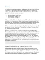
network handling of specific MS types. Figure 12-3
shows the structure of the
IMEI.
Figure 12-3. IMEI Structure
In the figure, the Type Approval Code (TAC) identifies the country in which the
p
hone's type approval was sought, and its approval number. The first two digits of
the TAC represent the country of approval. The Final Assembly Code (FAC)
identifies the facility where the phone was assembled. Table 12-1
shows the codes
that are currently in effect. The Serial Number (SNR) is an individual serial
number that uniquely identifies each MS (within each TAC and FAC).
Table 12-1. Final Assembly Codes
Code Facility
01, 02 AEG
07, 40 Motorola
10, 20 Nokia
30 Ericsson
40, 41, 44 Siemens
47 Option International
50 Bosch
51 Sony
51 Siemens
51 Ericsson
60 Alcatel
70 Sagem
75 Dancall
80 Philips
85 Panasonic
The IMEI is used for several fundamental network operations, such as when an MS
is switched on; the IMEI number is transmitted and checked against a black/gray
list. Operations that involve the IMEI are further discussed in later sections of this
chapter.
In addition to current BCD coding, 3GPP is currently proposing to change the
IMEI message structure to allow the use of hexadecimal coding. This would allow
the production of 16.7 million mobile terminals with one TAC+FAC combination.
To display the IMEI on most MSs, enter *#06# on the keypad. This is useful for
insurance purposes and allows the device to be blocked from network access,
should it be stolen (network permitting).
IMSI
Each subscriber is assigned a unique number, which is known as the IMSI. The
IMSI is the only absolute identity a subscriber has within GSM, and as such, it is
stored on the SIM. The SIM is a credit size, or quarter-credit card size smart card
that contains the subscriber's subscription details and grants the subscriber service
when placed into a piece of ME. Among other purposes, it is used for subscriber
billing, identification, and authentication when roaming.
The IMSI is specified in GSM 03.03, by 3GPP in TS 23.003, and the ITU in E.212.
Figure 12-4
shows an IMSI's format.
Figure 12-4. IMEI Structure
In Figure 12-4
, the Mobile Country Code (MCC) identifies the mobile subscriber's
country of domicile. The Mobile Network Code (MNC) identifies the subscriber's
home GSM PLMN.
The Mobile Station Identification Number (MSIN) identifies the mobile
subscriber. The National Mobile Station Identity (NMSI) is the name given to
MNC+MSIN fields.
The MCN's administration is the National Regulatory Authority's (NRAs)
responsibility—for example, OFTEL in the UK or Telcordia in the USA—while
network operators are usually responsible for the MSIN's arrangement and
administration following the MNC assigned by the respective NRA. Appendix I
contains a list of MCCs and MNCs.
TMSI
A TMSI is an alias used by the VLR (and the SGSN in GPRS enabled networks) to
p
rotect subscriber confidentiality. Please see section VLR for a description of the
VLR. It is temporarily used as a substitute for the IMSI to limit the number of
times the IMSI is broadcast over the air interface because intruders could use the
IMSI to identify a GSM subscriber. TMSI is issued during the location update
p
rocedure. The VLR and SGSNs must be capable of correlating an allocated TMSI
with the MS's IMSI to which it is allocated. The VLR assigns the TMSI to an MS
during the subscriber's initial transaction with an MSC (for example, location
updating). Because the TMSI has only local significance (within an area controlled
by VLR), each network administrator can choose its structure to suit his needs. To
avoid double allocation under failure/recovery conditions, it is generally
considered good practice to make part of the TMSI related to time.
The TMSI is defined in 3GPP TS 23.003 [106
].
MSISDN
MSISDN is the number the calling party dials to reach the called party—in other
words, it is the mobile subscriber's directory number. This parameter refers to one
of the ISDN numbers that is assigned to a mobile subscriber in accordance with
ITU Recommendation E.213. A subscriber might have more than one MISDN on
their SIM; examples include an MISDN for voice and an MISDN for fax. You can
find additional MISDN details in GSM 03.02 and GSM 03.12. Figure 12-5
shows
the format of an MSISDN.
Figure 12-5. MSISDN (E.164) Structure
In Figure 12-5
, the National Destination Code (NDC) identifies the numbering area
with a country and/or network/services. Country Code (CC) identifies a specific
country, countries in an integrated NP, or a specific geographic area. Subscriber
N
umber (SN) identifies a subscriber in a network or numbering area.
MSRN
The Mobile Station Roaming Number (MSRN) is solely used to route an incoming
call. It is a temporary identifier that is used to route a call from the gateway MSC
to the serving MSC/VLR.
The serving MSC/VLR is the MSC/VLR for the area where the subscriber
currently roams. The VLR assigns an MSRN when it receives a request for routing
information from the HLR. When the call has been cleared down, the MSRN is
released back to the VLR.
Additional details about the MSRN can be found in GSM 03.03.
S
ubscriber Identit
y
Module (SIM)
SIM cards are like credit cards and identify the user to the GSM network. They can
be used with any GSM handset to provide phone access, ensure delivery of
appropriate services to that user, and automatically bill the subscriber's network
usage back to the home network.
As previously stated, GSM distinguishes between the subscriber and the MS. The
SIM determines the subscriber's cellular number, thus permitting the subscriber to
use other equipment (change MS) while maintaining one number and one bill. The
SIM is a chip that is embedded in a card approximately the size of a credit card, or
around a quarter of the size (the former tends to be outdated).
The SIM is the component that communicates directly with the VLR and indirectly
with the HLR. These two critical networks components will be described later in
this chapter.
B
ase Transceiver Station (BTS)
The base transceiver stations provide the connectively between the cellular
network and the MS via the Airinterface. The BTS houses the radio transceivers
that define a cell and handles the radio interface protocols with the mobile station.
B
ase Station Controller (BSC)
A number of BTSs are connected to the BSC on an interface that is known as the
Abis interface.
It manages the radio interface channels, such as setup, release, frequency hopping,
and handovers.
M
obile Switchin
g
Centre (MSC)
The MSC is the network subsystem's central component. Because a large number
of BSCs are connected to an MSC, an MSC is effectively a regular ISDN switch
that connects to the BSCs via the A-interface. The MSC provides routing of
incoming and outgoing calls and assigns user channels on the A-interface.
It acts like a normal switching node of the PSTN or ISDN and provides all the
necessary functionality for handling a mobile station, including registration,
authentication, location updating, inter-MSC handovers, and call routing to a
roaming subscriber.
The MSC also provides the connection to the public fixed networks.
Together with the MSC, the HLR and VLR provide GSM call routing and roaming
capabilities.
H
ome Location Re
g
ister (HLR)
The HLR can be regarded as a huge database that contains the information for
hundreds of thousands of subscribers. Every PLMN has at least one HLR. While
there is logically one HLR per GSM network, it might be implemented as a
distributed database.
The HLR contains all administrative data that is related to each subscriber, who is
registered in the corresponding GSM network, along with his current location. The
location of each mobile station that belongs to the HLR is stored in order to be able
to route calls to the mobile subscribers served by that HLR. The location
information is simply the VLR address that currently serves the subscriber. An
HLR does not have direct control of MSCs.
Two numbers that are attached to each mobile subscription and stored in the HLR
include the IMSI and the MSISDN. The HLR also stores additional information,
including the location information (VLR), supplementary services, basic service
subscription information, and service restrictions (such as roaming permission).
GSM 03.08 details the subscriber data's organization.
Visitor Location Register (VLR)
Like the HLR, the VLR contains subscriber data. However, it only contains a
subset (selected administrative information) of the data that is necessary for call
control and provision of the subscribed services for each mobile that is currently
located in the geographical area controlled by the VLR. The VLR data is only
temporarily stored while the subscriber is in the area that is served by a particular
VLR. A VLR is responsible for one or several MSC areas. When a subscriber
roams into a new MSC area, a location updating procedure is applied. When the
subscriber roams out of the area that is served by the VLR, the HLR requests that it
remove the subscriber-related data.
Although the VLR can be implemented as an independent unit, to date, all
manufacturers of switching equipment implement the VLR with the MSC so the
geographical area controlled by the MSC corresponds to that which is controlled
by the VLR. The proximity of the VLR information to the MSC speeds up access
to information that the MSC requires during a call.
E
quipment Identit
y
Re
g
ister (EIR)
The EIR is a database that contains a list of all valid mobile equipment on the
network. Each MS is identified by its IMEI. An IMEI is marked as invalid if it has
been reported stolen or is not type approved.
The EIR contains a list of stolen MSs. Because the subscriber identity can simply
be changed by inserting a new SIM, the theft of GSM MSs is attractive. The EIR
allows a call bar to be placed on stolen MSs. This is possible because each MS has
a unique IMEI.
A
uthentication Center (AuC)
The AuC is a protected database that stores a copy of the secret key that is stored in
the subscriber's SIM card and is used for authentication and ciphering on the radio
channel.
S
ervin
g
GPRS Support Node (SGSN)
A SGSN is responsible for delivering data packets from and to the mobile stations
within its geographical service area. Its tasks include packet routing and transfer,
mobility management (attach/detach and location management), logical link
management, and authentication and charging functions. The location register of
the SGSN stores location information (such as current cell and current VLR) and
user profiles (such as IMSI and address(es) used in the packet data network) of all
GPRS users who are registered with this SGSN.
The SGSN delivers packets to mobile stations within its service area. SGSNs
detect subscribers in their service area, query HLRs to obtain subscriber profiles,
and maintain a record of their location.
Gateway GPRS Support Node (GGSN)
GGSNs maintain routing information that is necessary to tunnel the Protocol Data
Units (PDUs) to the SGSNs that service specific mobile stations. Other functions
include network and subscriber screening and address mapping.