Signaling System No.7 Protocol Architecture And Sevices part 46 potx
Bạn đang xem bản rút gọn của tài liệu. Xem và tải ngay bản đầy đủ của tài liệu tại đây (49.45 KB, 6 trang )
Interfaces and Protocols
The previous section introduced GSM network architecture, and this section
introduces the SS7/C7 protocols that are used. It also discusses interfaces, because
different protocols are used on different interfaces. The SS7/C7 protocols MTP,
SCCP, TUP, ISUP are protocols that were used before digital wireless networks
were available. The final part of this section introduces SS7/C7 protocols that were
specifically developed for GSM.
Table 12-2
summarizes the interfaces and protocols that are used in GSM.
Table 12-2. GSM Interfaces and Protocols
Interface Between Description
U
m
MS-BSS The air interface is used for exchanges between a MS
and a BSS. LAPDm, a modified version of the ISDN
LAPD, is used for signaling.
Abis BSC-BTS This is a BSS internal interface that links the BSC and a
BTS; it has not been standardized. The Abis interface
allows control of radio equipment and radio frequency
allocation in the BTS.
A BSS-MSC The A interface is between the BSS and the MSC. It
manages the allocation of suitable radio resources to the
MSs and mobility management. It uses the BSSAP
protocols (BSSMAP and DTAP).
B MSC-VLR The B interface handles signaling between the MSC and
the VLR. It uses the MAP/B protocol. Most MSCs are
associated with a VLR, making the B interface
"internal." Whenever the MSC needs to access data
regarding an MS that is located in its area, it interrogates
the VLR using the MAP/B protocol over the B interface.
C GMSC-
HLR or
SMSG-
HLR
The C interface is between the HLR and a GMSC or a
SMSC. Each call that originates outside of GSM (such as
an MS terminating call from the PSTN) must go through
a gateway to obtain the routing information that is
required to complete the call, and the MAP/C protocol
over the C interface is used for this purpose. Also, the
MSC can optionally forward billing information to the
HLR after call clearing.
D HLR-VLR The D interface is between the HLR and VLR, and uses
the MAP/D protocol to exchange data related to the
location of the MS and subsets of subscriber data.
E MSC-MSC The E interface connects MSCs. The E interface
exchanges data that is related to handover between the
anchor and relay MSCs using the MAP/E protocol. The
E interface can also be used to connect the GMSC to an
SMSC.
F MSC-EIR The F interface connects the MSC to the EIR and uses
the MAP/F protocol to verify the status of the IMEI that
the MSC has retrieved from the MS.
G VLR-VLR The G interface interconnects two VLRs of different
MSCs and uses the MAP/G protocol to transfer
subscriber information—for example, during a location
update procedure.
H MSC-
SMSG
The H interface is located between the MSC and the
SMSG and uses the MAP/H protocol to support the
transfer of short messages. Again, GSM as well as
ANSI-41 is unknown, but H in ANSI-41 is used for
HLR–AC interface.
I MSC-MS The I interface is the interface between the MSC and the
MS. Messages exchanged over the I interface are
transparently relayed through the BSS.
In terms of the physical layer, the air interface (MS-BTS) uses RF radio
transmission. The A-bis interface (BTS-BSC) uses 64 kbps over whatever medium
is most convenient for installation: wire, optical, or microwave. All other interfaces
in the GSM system use SS7/C7s MTP1 at the physical layer.
The data link layer that is used at the air interface (MS-BTS) is LAP-Dm; LAP-D
is the data link layer that is used at the A-bis interface (BTS-BSC). All other
interfaces in the GSM system use SS7/C7s MTP2 at the data link layer.
The air interface (MS-BTS) and the Abis interface (BTS-BSC) do not have a
network layer. All other interfaces in the GSM system use SS7/C7s MTP3 and
SCCP at the network layer.
The transport, session, and presentation layers are not used in SS7/C7—these
functions are grouped together at the application layer, which is known as Level 4
in SS7/C7. GSM interfaces to fixed-line networks using ISUP or TUP (TUP is
never used in North America).
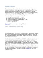
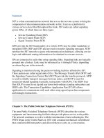
Figure 12-6
shows the SS7 protocols that operate at each interface.
Figure 12-6. Protocols Operating at Each Interface
All of the interfaces around the MSC use SS7/C7-based protocols. The B, C, D, F,
and G interfaces are referred to as MAP interfaces. These either connect the MSC
to registers or connect registers to other registers. The E interface supports the
MAP protocol and calls setup protocols (ISUP/ TUP). This interface connects one
MSC to another MSC within the same network or to another network's MSC.
By this point, you can gather that different functional entities (e.g. HLR, MSC, and
so on) run the required and therefore differing stack of SS7/C7 protocols. In
relation to the following diagram, remember that the MSC runs MAP-MSC, and
that MAP-VLR and the HLR run MAP-HLR.
Figure 12-7. Protocols Required for Functional Entities
[View full size image]
B
SSAP (DTAP/BSSMAP)
On the A interface, an application part known as the BSSAP is used. BSSAP can
be further separated into the base station subsystem management application part
(BSSMAP) and the direct transfer application part (DTAP).
N
either the BTS nor the BSC interpret CM and MM messages. They are simply
exchanged with the MSC or the MS using the DTAP protocol on the A interface.
RR messages are sent between the BSC and MSC using the BSSAP.
BSSAP includes all messages exchanged between the BSC and the MSC that the
BSC actually processes—examples include PAGING, HND_CMD, and the
RESET message. More generally, BSSAP comprises all messages that are
exchanged as RR messages between MSC and BSC, and messages that are used
for call-control tasks between the BSC and the MSC.
The DTAP comprises all messages that the subsystem of the NSS and the MS
exchange. DTAP transports messages between the MS and the MSC, in which the
BSC has just the relaying function.
M
obile Application Part (MAP)
The MAP is an extension of the SS7/C7 protocols that are added to support cellular
networks. It defines the operations between the MSC, the HLR, the VLR, the EIR,
and the fixed-line network. It comes in two incompatible variants: GSM-MAP and
ANSI-41 MAP. While GSM-MAP only supports GSM, ANSI-41 supports AMPS,
N
AMPS, D-AMPS/TDMA, CDMA (cdma One and cdma 2000), and GSM. GSM-
MAP is the international version, while ANSI-41 is the North American version.
The MAP is used to define the operations between the network components (such
as MSC, BTS, BSC, HLR, VLR, EIR, MS, and SGSN/GGSN in GPRS). This
involves the transfer of information between the components using noncircuit-
related signaling. MAP signaling enables location updating, handover, roaming
functionality, authentication, incoming call routing, and SMS. MAP specifies a set
of services and the information flows between GSM components to implement
these services. MAP can be considered an extension of the SS7/C7 protocol suite
created specifically for GSM and ANSI-41 networks.
MAP uses TCAP over SCCP and MTP. TCAP correlates between individual
operations. The TCAP transaction sublayer manages transactions on an end-to-end
b
asis. The TCAP component sublayer correlates commands and responses within a
dialog. Chapter 10
, "Transaction Capabilities Application Part (TCAP)," describes
TCAP in more detail.
MAP protocols are designated MAP/B–MAP/H, according to the interface on
which the protocol functions. For example, the MAP signaling between the GMSC
and the HLR is MAP/F.
Figure 12-8 shows the specific MAP-n protocols. The PCS 1900 specifications use
the same MAP interfaces, but PCS 1900 also defines MAP-H.
Figure 12-8. MAP-n Protocols
[View full size image]
MAP allows implementation of functions such as location updating/roaming, SMS
delivery, handover, authentication, and incoming call routing information. The
MAP protocol uses the TCAP protocol to transfer real-time information (between
N
SS components).
• MAP provides the functionality to route calls to and from the mobile
subscribers—it has the mechanisms necessary for transferring information
relating to subscribers roaming between network entities in the PLMN.
• The U.S. version is known as ANSI-41-MAP (standardized by EIA/TIA).
• The international version is known as GSM-MAP (standardized by
ITU/ETSI).
MAP only makes use of the connectionless classes (0 or 1) of the SCCP.
Table 12-4 shows the SCCP Subsystem Numbers (SSNs) that are specified for
MAP.
Table 12-3. SSNs Used by MAP
SCCP Subsystem
Numbers Use
0 0 0 0 0 1 0 1 For the entire MAP (reserved for possible future
use)
0 0 0 0 0 1 1 0 HLR
0 0 0 0 0 1 1 1 VLR
0 0 0 0 1 0 0 0 MSC
0 0 0 0 1 0 0 1 EIR
0 0 0 0 1 0 1 0 Allocated for evolution (possible Authentication
centre)