Signaling System No.7 Protocol Architecture And Sevices part 50 doc
Bạn đang xem bản rút gọn của tài liệu. Xem và tải ngay bản đầy đủ của tài liệu tại đây (60.08 KB, 13 trang )
Short Message Service (SMS)
SMS provides paging functionality for alphanumeric messages of up to 160
characters to be exchanged with other GSM users. The network itself can also
generate messages and broadcast to multiple MSs or to a specific MS. For
example, a welcome message can be sent to a subscriber when he or she roams
onto a new network; in addition, it can provide useful information, such as how to
retrieve voicemail. The SMS service also transfers ring tones and logos to the MS.
The SMS slightly blurs the image of the user traffic being separate from signaling
because, in a sense, the messages are user traffic; they are for human processing
(written and read), rather than for communication between network entities.
The SMS does not have subcategories. It has the following operations:
• forwardSM
• sendRoutingInfoForSM
• reportSMDeliveryStatus
• readyForSM
• alertServiceCentre
• informServiceCentre
The following sections examine each of these.
f
orwardS
M
Both the mobile originating (MO-SMS) and mobile terminating SMS (MT-SMS)
p
rocedures use the forwardSM operation to carry text messages between the MSC
where the subscriber roams and the SMS-IWMSC or the SMS-GMSC,
respectively. Figure 13-8
shows the MO-SMS procedure.
Figure 13-8. MAP Operations Involved in Sending an SMS from MS to the SMS-
SC
In Appendix L
, Example L-6 contains a trace that shows the decode of a MAP
operation forwardSM, including its SMS text.
s
endRoutin
g
In
f
oForS
M
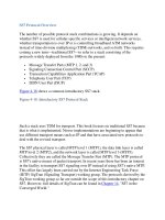
The SMS-GMSC uses this message during an MT-SMS to deliver an SMS to the
MSC in whose area the subscriber is currently roaming. The message contains the
subscriber's MSISDN, and the result contains the destination MSC's ISDN number.
SCCP then uses this ISDN number to deliver the SMS using a forwardSM
message. Figure 13-9
shows the MT-SMS procedure.
Figure 13-9. MAP Operations Involved in Sending an SMS from the SMS-SC to
the MS
[View full size image]
In Appendix L
, Example L-2 shows a trace showing a VLR's decode calling an
HLR (to perform a location update).
reportSMDeliveryStatus
If the SMS-SC cannot deliver the MT-SMS to the MS (because the subscriber is
not reachable, for example), then the SMS-SC returns a negative result to the SMS-
GMSC. Upon receiving this result, the SMS-GMSC sends a
reportSMDeliveryStatus to the HLR, which, in turn, sets a message waiting flag in
the appropriate subscriber data. The HLR also sends an alertServiceCentre
message to the SMS-IWMSC to inform it about the negative SM delivery and
waits until the subscriber can be reached. When the VLR (also aware of SM
delivery failure) detects that the subscriber is again reachable, it sends a readforSM
message to the HLR. The HLR, in turn, sends an alertServiceCentre message to the
SMS-IWMSC, which informs the SMS-SC. The delivery process then begins again
with a forwardSM message.
N
OTE
The previous section also pertains to the readyForSM and alertServiceCentre.
informServiceCentre
If a sendRoutingInfoForSM is received for a subscriber that is currently
unavailable, the HLR sends this message to the SMS-GMSC.
< Day Day Up >
< Day Day Up >
Summary
MAP primary use is to allow calls to be delivered to mobile subscribers. Unlike
with fixed-line networks, the subscriber's location cannot be determined from the
numbering scheme that is used in the network. Therefore, the subscriber's location
must be known in real-time so a call can be connected to the nearest switch to the
mobile subscriber. MAP keeps track of a mobile subscriber and provides other
functionality, including allowing mobile subscribers to send alphanumeric two-
way text between handsets; this is known as SMS. MAP also provides mobile
operator's with the functionality to manage a subscriber's subscription so that
services can be added and removed in real-time.
< Day Day Up >
< Day Day Up >
Chapter 14. SS7 in the Converged World
The "Converged World" of Next Generation Networks (NGNs) brings with it the
p
romise of voice, video, and data over a single broadband network. This transition
from the traditional circuit-switched networks to packet-switched networks has
been underway for many years, and Voice over IP (VoIP) is now leading the
transition. The immediate benefits of NGNs are decreased cost of infrastructure
and improved ease of management. Longer-term benefits include the ability to
rapidly deploy new services.
This chapter introduces the next generation architecture and presents a detailed
discussion of the Signaling Transport (SigTran) protocols between the Media
Gateway Controller (MGC) and the Signaling Gateway (SG). It also discusses the
Transport Adaptation Layer Interface (TALI) and briefly covers an early Cisco
SS7 over IP solution. Finally, it looks at the role of SS7 in decentralized VoIP
signaling protocols such as Session Initiation Protocol (SIP) [124] and H.323
[125
].
< Day Day Up >
< Day Day Up >
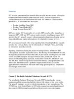
Next Generation Architecture
One NGN architecture for VoIP with centralized call processing decomposes the
functional elements of a traditional circuit switch into specialized components with
open interfaces. Following are the key logical elements of this reconstruction are
the following:
• The MG handles the media, or bearer, interface. It converts media from the
format used in one network to the format required in another network. For
example, it can terminate the TDM trunks from the PSTN, packetize and
optionally compress the audio signals, and then deliver the packets to the IP
network using the Real Time Protocol (RTP) [120
].
• The MGC (also known as a Call Agent) contains the call processing. In
addition, it manages the resources of the MGs that it controls. The MGC
controls the MG using a control protocol to set up the RTP connections and
control the analog or TDM endpoint in the MG.
• The SG sits at the edge of an IP network and terminates circuit-switched
network signaling, such as SS7 or ISDN, from the circuit-switched network.
It transports, or backhauls, this signaling to the MGC or other IP-based
application endpoint.
Figure 14-1
shows an example of these logical elements and their connections.
Figure 14-1. NGNs—Sample Architecture
[View full size image]
As Figure 14-1
shows, the evolution of specialized components provided open
interfaces between these logical elements. The Internet Engineering Task Forces
(IETF) created two working groups to address these open interfaces at the same
time that ITU-T SG16 began to study the MGC to MG interface. Thus, the
definition of the bearer control protocol between the MG and the MGC became a
j
oint effort by the IETF MeGaCo (MGC) Working Group and the ITU-T SG16.
The output from these groups is known as the Megaco [RFC 3015] [121
] protocol
in the IETF, and the H.248 [122
] protocol in the ITU-T.
Also worth mentioning is a precursor to Megaco protocol: the Media Gateway
Control Protocol (MGCP) [RFC 3435] [123].
N
OTE
MGCP was originally published in RFC 2705, which has now been replaced by
RFC 3435.
MGCP can also be used as a control protocol between an MGC MGCU (TG) and
an MG. While MGCP is defined by an Informational (versus standards track) RFC,
it is commonly used in many products today because the specification was
available before Megaco and H.248 were finished. Both MGCP and Megaco/H.248
assume that the call control intelligence is outside the MGs and that the MGC
handles it.
Closely related to the MGCP protocol are the PacketCable protocols, Network-
Based Call Signaling (NCS) and PSTN Gateway Call Signaling Protocol (TGCP).
These protocols provide functionality similar to MGCP for cable-based networks.
The IETF SigTran Working Group focused on the SG to MGC open interface. The
Working Group produced a set of standard protocols to address the needs and
requirements of this interface.
< Day Day Up >
< Day Day Up >
SigTran
There has been interest in interworking SS7 and IP for quite some time. However,
the initial solutions were proprietary. This began to change in the late 1990s, when
an effort to standardize Switched Circuit Network (SCN) signaling (SS7) over IP
transport began in the IETF.
The IETF SigTran Working Group was founded after a Birds of a Feather (BOF)
session, which was held at the Chicago 1998 IETF meeting, to discuss transport of
telephony signaling over packet networks. The result of the BOF was the creation
of the SigTran Working Group to do the following:
• Define architectural and performance requirements for transporting SCN
signaling over IP.
• Evaluate existing transport protocols, and, if necessary, define a new
transport protocol to meet the needs and requirements of transporting SCN
signaling.
• Define methods of encapsulating the various SCN signaling protocols.
The SigTran Working Group first met at the Orlando 1998 IETF meeting.
The SigTran Working Group defined the framework architecture and performance
requirements in RFC 2719 [126
]. The framework included the concept of
reconstructing the traditional circuit switch into MGC, MG, and SG elements,
thereby separating the signaling and the media control plane.
The framework document identified three necessary components for the SigTran
p
rotocol stack:
• A set of adaptation layers that support the primitives of SCN telephony
signaling protocols
• A common signaling transport protocol that meets the requirements of
transporting telephony signaling
• IP [127] network protocol
Figure 14-2 shows the three layers of the protocol stack.
Figure 14-2. SigTran Protocol Layers
Further functional requirements were defined for the transport protocol and
adaptation layers. The transport had to be independent of the telephony protocol it
carried, and, more importantly, had to meet the stringent timing and reliability
requirements of that telephony protocol.
The Working Group began evaluating the two commonly used transport protocols,
User Datagram Protocol (UDP) [128
] and Transport Control Protocol (TCP) [129],
against these requirements. UDP was quickly ruled out because it did not meet the
basic requirements for reliable, in-order transport. While TCP met the basic
requirements, it was found to have several limitations. A team of engineers from
Telcordia (formerly Bellcore) completed an analysis of TCP against SS7's
p
erformance and reliability requirements. Their analysis was documented in an
IETF draft [130
], which introduced the following limitations of TCP:
• Head-of-line blocking— Because TCP delivery is strictly sequential, a
single packet loss can cause subsequent packets to also be delayed. The
analysis showed that a 1% packet loss would cause 9% of the packets being
delayed greater than the one-way delay time.
• Timer granularity— While this is not a limitation of the TCP protocol, it is a
limitation of most implementations of TCP. The retransmission timer is
often large (typically one second) and is not tunable.
The Working Group noted additional TCP limitations, including the following:
• A lack of built-in support for multihoming. This support is necessary for
meeting reliability requirements, such as five 9s and no single point of
failure.
• Also, because of a timer granularity issue and the lack of a built-in heartbeat
mechanism, it takes a long time to detect failure (such as a network failure)
in a TCP connection.
Because of the deficiencies of UDP and TCP, a new transport protocol, Stream
Control Transmission Protocol (SCTP) [131
], was developed for transporting SCN
signaling. Note that SCTP is a generic transport that can be used for other
applications equally well.
S
tream Control Transmission Protocol (SCTP)
The SigTran Working Group presented several proposals for a new transport
p
rotocol. One proposal was Multinetwork Datagram Transmission Protocol
(MDTP), which became the foundation for SCTP. RFCNext Generation
N
etwork2960 defines SCTP, which has been updated with RFC 3309 [132] to
replace the checksum mechanism with a 32-bit CRC mechanism. Further, there is
an SCTP Implementers Guide [133
] that contains corrections and clarifications to
RFC 2960.
SCTP provides the following features:
• Acknowledged error-free, nonduplicated transfer of user data
• Data segmentation to conform to path MTU size (dynamically assigned)
• Ordered (sequential) delivery of user messages on a per "stream" basis
• Option for unordered delivery of user messages
• Network-level fault tolerance through the support of multihoming
• Explicit indications of application protocol in the user message
• Congestion avoidance behavior, similar to TCP
• Bundling and fragmenting of user data
• Protection against blind denial of service and blind masquerade attacks
• Graceful termination of association
• Heartbeat mechanism, which provides continuous monitoring of reachability
SCTP is a connection-oriented protocol. Each end of the connection is a SCTP
endpoint. An endpoint is defined by the SCTP transport address, which consists of
one or more IP addresses and an SCTP port. The two endpoints pass state
information in an initialization procedure to create an SCTP association. After the
association has been created, user data can be passed. Figure 14-3
provides an
example of two SCTP endpoints in an association.
Figure 14-3. SCTP Endpoints in an Association
In Figure 14-3
, Host A has endpoint [10.82.82.4, 10.82.83.4 : 2905] and Host B
has endpoint [10.82.82.24, 10.82.83.24 : 2905]. The association is the combination
of the two endpoints.
The following sections discuss how SCTP addresses the deficiencies of TCP that
are related to meeting the requirements for delivering telephony signaling over IP.
For additional details about the internals of SCTP, the Stream Control
Transmission Protocol, A Reference Guide, by Randall Stewart and Qiaobing Xie,
is a good resource.
Head-of-Line Blocking
SCTP uses streams as a means of decreasing the impact of head-of-line blocking.
In SCTP, a stream is a unidirectional channel within an association. Streams
p
rovide the ability to send separate sequences of ordered messages that are
independent of one another.
Figure 14-4
provides an example of head-of-line blocking with TCP. When packet
2 is dropped, packets 3 to 5 cannot be delivered to the application because TCP
p
rovides in-order delivery.
Figure 14-4. Example of Head-of-Line Blocking in TCP
SCTP provides the ability to have multiple streams within an association. Each
stream provides reliable delivery of ordered messages that are independent of other
streams. Figure 14-5
shows an example of how SCTP can help resolve head-of-line
blocking. In this example, packet 2 is dropped again. However, because packets 3,
4, and 5 belong to a different stream, they can be delivered to the application
without delay.
Figure 14-5. Use of Streams in SCTP to Avoid Head-of-Line Blocking
Failure Detection
Quick failure detection and recovery is important for meeting the performance and
reliability requirements that are specified for transporting SCN signaling. For a
multihomed host, two types of failures can occur:
• One or more destination addresses in the peer endpoint become unavailable
or unreachable.
• The peer endpoint becomes unavailable or unreachable.
A destination address can become unreachable for one of several reasons. First,
there could be a failure in the network path to the destination address, or a failure
in the Network Interface Card (NIC) that supports the destination address.
Likewise, a peer endpoint can become unavailable for several reasons. By
definition, the peer endpoint is unavailable or unreachable if all of its destination
addresses are unavailable or unreachable. SCTP provides two mechanisms for
detecting failures:
1. Use of the Path.Max.Retrans threshold, which is the maximum number of
consecutive retransmission that are allowed for a path.
2. Use of the heartbeat mechanism.
When an endpoint sends a data message to a particular destination address, an
acknowledgement is expected in return. If the acknowledgement has not been
received when the retransmission timer expires, SCTP increases an error counter
for that destination address and then retransmits the data message to the same
destination or to another destination address, if one is available. The destination
address is considered unreachable if the error counter reaches a defined threshold
(Path.Max.Retrans).
The other mechanism for detecting failures is a heartbeat mechanism. This
mechanism is useful for monitoring idle destination addresses, such as a
destination address that has not received a data within the heartbeat period. The
heartbeat is sent periodically, based on a configured heartbeat timer. If a heartbeat
response is not received, the same error counter is increased. Again, when the error
counter reaches a defined threshold (Path.Max.Retrans), the destination address is
considered unavailable or unreachable.
To determine the availability of the peer endpoint, an error counter is kept for the
p
eer endpoint. This error counter represents the number of consecutive times the
retransmission timer has expired. It is also increased each time a heartbeat is not
acknowledged. When this error counter reaches a defined threshold
(Association.Max.Retrans), the peer endpoint is considered unavailable or
unreachable.
SCTP enables faster failure detection by encouraging implementations to support
tunable parameters. As noted, TCP is limited in this respect because most
implementations do not allow the application to tune key TCP parameters. SCTP
encourages an implementation to support tunable parameters through the definition
of the upper-layer interface to the application. In RFC 2960, Section 10 contains an
example that describes the upper-layer interface definition. One function in this
definition, SETPROTOCOLPARAMETERS(), provides a means setoff-setting
p
arameters such as minRTO, maxRTO, and maxPathRetrans. More importantly,
the SCTP sockets Application Programmer Interface (API) [134
] defines a socket
option (SCTP_RTOINFO) for setting key parameters.
Multihoming and Failure Recovery
Multihoming provides a means for path level redundancy. This feature enables
SCTP endpoints to support multiple transport addresses. Each transport address is
equivalent to a different path for sending and receiving data through the network.
Figure 14-6
shows an example of multihoming.
Figure 14-6. Multihoming Support in SCTP
In the case of multihoming, one network path is selected as the primary path. Data
is transmitted on the primary path while that path is available. If a packet gets
dropped—for instance, because of a failure in the path—the retransmission should
be sent on the alternate path. Figure 14-7
provides an example based on the
diagram in Figure 14-6
, with the primary path between IP1 and IP3 (the 10.82.82.x
network) and the alternate path between IP2 and IP4 (the 10.82.83.x network). In
this example, the packet with Transmission Sequence Number (TSN) 1 is
retransmitted on the alternate path.
Figure 14-7. Failure Recovery Example
Retransmitting on the alternate path decreases failure recovery time. Further, if the
p
rimary path fails, the alternate path is automatically selected as the primary path.
The path failure recovery mechanism is completely transparent to the application
that uses SCTP.
Proposed Additions
The IETF Transport Working Group proposes two promising additions to the
SCTP protocol:
• Dynamic Address Reconfiguration [135]
• Partial Reliability [136]
The first proposal is to allow for IP address information reconfiguration on an
existing association. This feature can be useful for hardware that provides for hot
swap of an Ethernet card, for example. A new Ethernet card could be added and
the Ethernet card's IP address could then be added to the association without
requiring system downtime.
The second proposal allows for partially reliable transport on a per message basis.
In other words, the application can determine how a message should be treated if it
needs to be retransmitted. For instance, the application can decide that a message is
stale and no longer useful if it has not been delivered for two seconds. SCTP then
moves past that message and stops retransmitting it.