Signaling System No.7 Protocol Architecture And Sevices part 57 pps
Bạn đang xem bản rút gọn của tài liệu. Xem và tải ngay bản đầy đủ của tài liệu tại đây (56.12 KB, 9 trang )
MTP Level 2 User Adaptation (M2UA)
The M2UA protocol defines the layer split between MTP Level 2 and MTP Level
3. M2UA is defined by RFC 3331 [140
]. The M2UA protocol can be used between
a SG, which is called a Signaling Link Terminal (SLT), and an MGC.
The SG would terminate standard SS7 links using MTP Level 1 and MTP Level 2
to provide reliable transport of MTP Level 3 messages to the SEP or STP. The SG
also provides reliable transfer of MTP Level 2 primitives over IP, using SCTP as
the transport protocol.
Figure 14-18
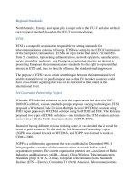
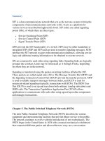
shows an example of an SG to the MGC application of M2UA. The
SEP is a SEP in the SS7 network. Just as it does for M3UA, NIF stands for Nodal
Interworking Function. It is the software in the SG that provides the SS7 to IP
network interworking.
Figure 14-18. Example of M2UA Between SG and MGC
Although not discussed, M2UA can be used between two SGs, but not in a peer-to-
p
eer arrangement. One SG would terminate the SS7 links and backhaul the MTP
Level 3 messages to the other SG, which would terminate MTP Level 3.
As noted, the M2UA layer supports the MTP Level 2 to MTP Level 3 primitive
boundary, including support for link alignment, message retrieval during link
changeover, remote and local processor outage, and link congestion notifications.
M
essa
g
es and Formats
M2UA uses the common header and TLV format for parameters that were defined
in the M3UA section. In addition, M2UA introduces an M2UA specific header that
is required because an Application Server can support more than one Interface
Identifier.
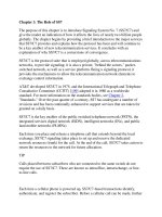
Figure 14-19
shows the M2UA specific header, which is placed between the
common message header and message-specific parameters. Note that it follows the
TLV format. The Interface Identifier can be an integer-based or text-
b
ased (ASCII)
value. If it is integer-based, the length is always equal to eight. If it is text-based,
the length is based on the length of the ASCII string, up to a maximum of 255
octets.
Figure 14-19. M2UA Specific Message Header
Table 14-3
lists the message classes and message types for M2UA.
Table 14-3. M2UA Message Classes and Types
Msg Class
Value Message Class and Type Names
Msg Type
Value
0 Management (MGMT) messages
Error message 0
Notify message 1
3 ASP State Maintenance (ASPSM) messages
ASP Up 1
ASP Down 2
Heartbeat 3
ASP Up Acknowledge 4
ASP Down Acknowledge 5
Heartbeat Acknowledge 6
4 ASP Traffic Maintenance (ASPTM)
messages
ASP Active 1
ASP Inactive 2
ASP Active Acknowledge 3
ASP Inactive Acknowledge 4
6 MTP2 User Adaptation (MAUP) messages
Data 1
Establish Request 2
Establish Confirm 3
Release Request 4
Release Confirm 5
Release Indication 6
State Request 7
State Confirm 8
State Indication 9
Data Retrieval Request 10
Data Retrieval Confirm 11
Data Retrieval Indication 12
Data Retrieval Complete Indication 13
Congestion Indication 14
Data Acknowledge 15
10 Interface Identifier Management (IIM)
messages
Registration Request 1
Registration Response 2
Deregistration Request 3
Deregistration Response 4
MTP2 User Adaptation (MAUP) Messages
The MAUP messages support the interface boundary to MTP Level 3.
The Data message is an MAUP message that contains MTP Level 3 protocol data,
beginning with SIO—except in the case of the Japanese TTC [153
] variant. For the
TTC variant, the protocol data begins with the Length Indicator (LI) because its
first two bits are used for priority information.
The Data message can contain an optional Correlation Identifier that is generated
by the sender. This parameter is included to request an acknowledgement that the
M2UA peer has received the protocol data.
The following is a list of MAUP messages:
• Data Acknowledge
The Data Acknowledge message confirms the receipt of the Data message
that is specified by the Correlation Identifier.
• Establish Request and Confirm
The ASP sends an Establish Request message to request the alignment of an
SS7 link. The mode of the alignment defaults to Normal and can be changed
with the State Request message. When the link is aligned, the SGP sends an
Establish Confirm message.
• Release Request, Indication, and Confirm
The ASP sends a Release Request message to request that an SS7 link be
taken out of service. When the SS7 link transitions to out of service, the SGP
sends a Release Confirm message. If the SS7 link transitions to out of
service asynchronously (the SEP takes the link out of service), the SGP
sends a Release Indication message to notify the ASP.
• State Request, Indication, and Confirm
The ASP sends a State Request message to request an action, such as setting
link alignment state to emergency, clearing congestion, or flushing buffers
for the specified SS7 link. The SGP sends the State Confirm message to
confirm receipt of the State Request. The SGP sends the State Indication
message to indicate a local or remote process state change for the specified
SS7 link.
• Congestion Indication
The SGP sends the Congestion Indication to the ASP when there has been a
change in the congestion or discard status of the specified SS7 link. The
message accommodates those MTP variants that support multiple congestion
levels.
• Retrieval Request, Indication, Complete Indication, and Confirm
These messages are used for the link changeover procedure. The ASP starts
the procedure by using the Retrieval Request message to request the BSN
for the failed SS7 link. The SGP responds with the Retrieval Confirm
message. If there are any user data messages to retrieve, the MTP Level 3 on
the ASP can choose to retrieve them. Again, the Retrieval Request message
is used for this purpose. The SGP sends the user data messages in the
Retrieval and Retrieval Complete Indication messages.
MGMT Messages
The messages are the same as those described under M3UA. However, there are
some errors that are specific to M2UA. The "Invalid Interface Identifier" error
might indicate a misconfiguration between the SGP and ASP.
ASPSM and ASPTM Messages
As with the MGMT messages, the ASPSM and ASPTM messages are the same as
those described under M3UA. However, instead of Routing Context, Interface
Identifier is an optional field in the ASPTM messages.
Interface Identifier Management (IIM) Messages
The IIM messages provide a means of supporting the MTP Level 3 procedures for
automatic allocation of Signaling Terminals and Signaling Data Links. The
Registration Request requests that an Interface Identifier be assigned to a Signaling
Data Terminal and Signaling Data Link Identifier pair. The Registration Response
p
rovides a result (success or fail) for the registration and, if successful, the
assigned Interface Identifier. The ASP can deregister the Interface Identifier (in
other words, give it back to the pool) using the Deregistration Request message.
The SGP confirms this request using the Deregistration Response message.
SS7 Variant Specifics
Like the other UAs, M2UA provides support for all SS7 variants. There is one
p
arameter that is specific to the Japanese TTC [153] variant. A TTC-specific
Protocol Data parameter provides the means of carrying priority information. This
Protocol Data parameter differs from the generic Protocol Data parameter by
starting with the Length Indicator (the Japanese TTC variant uses the spare bits of
this octet for priority information), rather than the SIO. The Congestion Indication
message also accommodates MTP variants that support multiple congestion levels.
Message Flow Examples
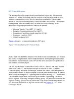
Figure 14-20
shows a message flow example for an SGP that supports an
Application Server containing IIDs 1 and 2. The ASP brings the Application
Server to the AS-ACTIVE state by sending the appropriate ASPSM and ASPTM
messages. It then decides to align the first SS7 link (identified by IID 1) in-service
using emergency alignment. Then, it requests to align the second SS7 link
(identified by IID 2) using normal (the default) alignment.
Figure 14-20. M2UA Message Flow Example
M
TP Level 2 Peer Adaptation (M2PA)
Similar to the M2UA layer, the MTP Level 2 Peer Adaptation (M2PA) layer
transports SS7 MTP Level 2 user (MTP Level 3) signaling messages over IP using
SCTP. However, in addition, M2PA supports full MTP Level 3 message handling
and network management between two SS7 nodes that communicate over an IP
network. An ID [141
] defines an M2PA, which is in the process of becoming an
RFC.
M2PA supports the following features:
• Seamless operation of MTP Level 3 protocol peers over an IP network
• Support for the MTP Level 2 to MTP Level 3 primitive boundary
• Support for the management of SCTP associations as IP links
• Support for reporting asynchronous status changes to layer management
M2PA can be used between a SG and a MGC, between a SG and an IPSP, and
between two IPSPs. In any scenario, both sides of the M2PA protocol must be
assigned an SS7 point code. Two IPSPs can use M2PA IP links and standard SS7
links simultaneously to send and receive MTP Level 3 messages.
Figure 14-21
shows an SG to MGC application of M2PA.
Figure 14-21. Example of M2PA Used Between a SG and a MGC
M2PA can also be used between two SGs. This configuration would be useful for
long-haul SS7 link replacement. Figure 14-22
shows an example of such a
configuration.
Figure 14-22. Example of M2PA Used Between Two SGs
[View full size image]
M2PA and M2UA Comparison
M2PA and M2UA are similar in that they both support the MTP Level 2 primitive
boundary to MTP Level 3, and they both transport MTP Level 3 data messages.
However, they also have some significant differences.
The differences arise from the treatment of the MTP Level 2 primitive boundary
interface. M2UA "backhauls," or transports, the boundary primitives by way of
M2UA messages between the M2UA peers. M2PA processes the boundary
p
rimitives, in effect replacing MTP Level 2 without necessarily repeating all of the
MTP Level 2 functionality. Therefore, M2PA provides an IP-based SS7 link. This
requires that the M2PA SG is an SS7 node with a point code. The M2UA SG does
not have such a requirement; rather, it shares the MGC or IPSP's point code.
M2PA Differences from Other UAs
M2PA does share the same common message header with the other UA layers, but
it is different in many ways. Because M2PA is a peer-to-peer with a single "IP
link" that is defined by a single association, there is no need for Routing Keys or
Interface Identifiers. Further, M2PA does not support the concepts of Application
Servers, ASPs, or SGP. M2PA's redundancy model is based on SS7. The peer-to-
p
eer connection based on a SCTP association supports a single SS7-based IP-link.
SS7 link sets support redundancy.
Messages and Formats
As noted, M2PA does support the common message header. In addition, M2PA
has a M2PA specific header that is used with each message. Figure 14-23
shows
the M2PA specific header.
Figure 14-23. M2PA Specific Message Header
As with MTP Level 2, Backward Sequence Number (BSN) is the Forward
Sequence Number (FSN) that was last received from the peer. FSN is the sequence
number of the user data message being sent.
Table 14-4
lists the message classes and message types for M2PA.
Table 14-4. M2PA Message Classes and Types
Msg Class Value Message Class and Type Names Msg Type Value
11 M2PA messages
User Data 1
Link Status 2
MTP2 Peer Adaptation Messages
The following are M2PA messages:
• User Data— The User Data message carries the MTP Level 3 Payload's SIO
and Signaling Information Field (SIF). It also contains a LI field to support
the Japanese TTC variant that requires two bits in the LI field to be used for
priority. However, the LI field is not used for any other purpose (such as to
indicate message length) and is set to zero.
• Link Status— The Link Status message is similar to the Link Signal Status
Unit (LSSU) in MTP Level 2. It is used to indicate the state of the "IP link."
The possible states are: Alignment, Proving Normal, Proving Emergency,
Ready, Processor Outage, Process Recovered, Busy, Busy Ended, and Out o
f
Service. The Proving message can contain optional filler to enable the SCTP
send window size to be increased (in other words, to move beyond the SCTP
slow start threshold) before the "IP link" is aligned.
Message Flow Example
Figure 14-24
shows a message flow example for aligning a link by using normal
p
roving between two SGs supporting M2PA. In this diagram, the timer information
is only shown for SG1. When alignment is complete, the M2PA peers inform their
respective MTP Level 3 stacks that the link is in-service; MTP Level 3 messages
can then be sent across the "IP link."
Figure 14-24. M2PA Message Flow Example