Signaling System No.7 Protocol Architecture And Sevices part 61 ppsx
Bạn đang xem bản rút gọn của tài liệu. Xem và tải ngay bản đầy đủ của tài liệu tại đây (59.97 KB, 12 trang )
MTP 2 Testing
The MTP 2 test specification is found in ITU Q.781 [87
]. The purpose of the tests
is to ensure complete validation and compatibility of an SP's MTP 2 protocol
according to ITU Q.703 [51
]. See Chapter 6, "Message Transfer Part 2 (MTP2),"
for a description of the MTP2 protocol.
The tests are split up by functional area into ten categories.
Table 16-1
shows the test categories and the tests that they contain.
Table 16-1. Test Categories and Numbers Found in Q.781
Category Test
Number(s)
Total
Link state control—expected signal units/orders 1.1–1.35 35
Link state control—unexpected signal units/orders 2.1–2.8 8
Transmission failure 3.1–3.8 8
Processor outage control 4.1–4.3 3
SU delimitation, alignment, error detection, and
correction
5.1–5.5 5
SUERM check 6.1–6.4 4
AERM check 7.1–7.4 4
Transmission and reception control (basic) 8.1–8.13 13
Transmission and reception control (PCR) 9.1–9.13 13
Congestion control 10.1–10.4 4
Totals 97
The remainder of this section explains fourteen of these tests, covering at least one
from each category. The tests explained include: 1.1, 1.5, 1.22, 1.28, 2.7, 3.1, 3.2,
4.1, 5.1, 6.1, 7.1, 8.3, 9.3, and 10.1. These numbers refer to the test numbers that
are allocated in Q.781. Many of the tests that are not used as examples are
variations of the example tests given; therefore, taking at least one test out of each
category gives the reader a good understanding of the test methods.
Test Configuration
A single link is used for MTP2 tests. Figure 16-1
shows a single link between SP A
and SP B. SP A is the device under test DUT, while SP B is the Tester.
Figure 16-1. Test Configuration Used for MTP2 Testing
E
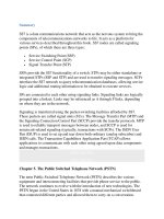
xample 1: Initialization (Power-up), Test 1.1
This test ensures that the DUT enters the correct state upon power up and that it is
used for both validation and compatibility testing purposes. It consists of two parts:
p
art (a) and part (b). Part (b) is the same test repeated in the reverse direction.
Part (a)
Before beginning this test, switch the DUT off and the tester on. This results in
status indication out of service (SIOS) periodically being sent in only one
direction, from the tester to the DUT.
The test begins when you power up the DUT. The DUT should periodically send
LSSUs with the SIOS in the direction SP A to SP B. The FIB and the BIB should
each be initialized to 1, and the FSN and BSN should both be set to 127. Figure 16-
2 shows the expected message sequence for this test.
Figure 16-2. Expected Message Sequence for Test 1.1 (a)
If the DUT sends an LSSU with the SIOS and the fields FIB, BIB, FSN, BSN are
initialized correctly, then test 1.1(a) should be considered passed.
Part (b)
Switch the DUT on and the tester off before beginning this test. This results in
SIOS periodically being sent in only one direction, from the DUT to the Tester.
The test begins when you power up the Tester. The Tester should periodically send
LSSUs with the SIOS in the direction SP B to SP A. The FIB and the BIB should
both be set to 1, and the FSN and BSN should both be set to 127. Figure 16-3
shows the expected message sequence for this test.
Figure 16-3. Expected Message Sequence
If the fields FIB, BIB, FSN, and BSN have been received correctly, then test 1.1(b)
should be considered passed.
E
xample 2: Normal Ali
g
nment—Correct Procedure (FISU), Test 1.5
This test ensures that the DUT can perform the normal alignment procedure, and
that the "in-service" state can be maintained once it has been achieved. It consists
of two parts, part (a) and part (b), which is the same test except that it uses two
octet LSSUs. Part (a) is used for both validation and compatibility testing
p
urposes, while part (b) is used for validation testing purposes only.
Part (a)
The link should be put in the "out-of-service" state before commencing this test.
As shown in Figure 16-4
, the test begins when you start the alignment procedure at
the DUT. The normal alignment procedure should follow; DUT should cease to
send SIOS and start sending SIO. Upon receiving SIO back from the Tester, it
should request normal alignment by sending SIN. Upon receiving SIN back from
the Tester, the "in-service" state should be entered. FISUs should flow in both
directions, and the DUT should remain in the "in-service" state.
Figure 16-4. Expected Message Sequence for Test 1.5
Consider the test passed if the DUT achieves link alignment, enters the "in-service"
state, and remains in the "in-service" state after FISUs have been exchanged.
Part (b)
Part (b) is exactly the same as part (a), except that the Tester should send the
LSSUs with a length of two octets rather than one.
E
xample 3: Individual End Sets Emer
g
enc
y
, Test 1.22
This test ensures that the DUT performs emergency alignment when requested by
the other side even when it perceives a normal condition, but that the other side
request emergency alignment. It is used for validation testing purposes only.
You should put the link in the "out-of-service" state before commencing this test.
The test begins when you start the alignment procedure at the Tester. The Tester
should request emergency alignment by sending LSSUs with emergency alignment
indication (SIEs). The DUT should be set to "perceive" normal alignment
conditions, and should thus cease to send SIOS, send back SIO, and then start
sending LSSUs with normal alignment indication (SINs).
Even though the DUT "perceives" that normal alignment should be carried, it
should carry out the alignment within the emergency proving period because it has
received a request from the other side for emergency alignment. Figure 16-5
shows
the expected message sequence for this test.
Figure 16-5. Expected Message Sequence for Test 1.22
P
e
is the emergency proving period, which can by measured by subtracting the time
stamp of the SIN from the time stamp for the FISU. Consider the test passed if the
alignment occurs within the emergency proving period.
E
xample 4: SIO Received Durin
g
Link In-Service, Test 1.28
This test ensures that the DUT can deactivate a link from the "in-service" state. It is
only used for validation testing purposes.
The link should be put in the in-service state before commencing this test.
The test begins by sending an LSSU with the SIO from the Tester to the DUT. The
DUT should then place the link in the out-of-service state returning an LSSU with
SIOS. It should also indicate "out-of-service" to MTP3 with reason "Received
SIO." Figure 16-6
shows the expected message sequence for this test.
Figure 16-6. Expected Message Sequence for Test 1.28
Consider the test passed if the DUT responds to the SIO reception by returning
SIOS.
E
xample 5: Unexpected Si
g
nal Units/Orders in "In-Service" State, Test 2.7
This test ensures that the DUT ignores a corrupt LSSU receipt and unexpected
requests from MTP3. The test is used for validation testing purposes only.
The link should be put in the in-service state before commencing this test; if it is
already in service, it should be put out of service, and then put back to the in-
service state.
The test begins by sending an LSSU with a corrupt status, or a status for which
there is no meaning (such as 00000110) to the DUT. A sequence of unexpected
MTP3 commands should be issued at the DUT. These commands are as follows:
• –command "Set Emergency"
• –command "Clear Emergency"
• –command "Clear Local Processor Outage" (LPO)
• –command "Start"
Figure 16-7
shows the expected message sequence for this test.
Figure 16-7. Expected Message Sequence for Test 2.7
Consider the test passed if the DUT ignores the corrupt LSSU status indication,
and the unexpected MTP3 commands.
E
xample 6: Link Ali
g
ned Read
y
(Break Tx Path), Test 3.1
This test ensures that the DUT responds correctly to a transmission failure that
SUERM detects by placing the link out of service when in the Aligned Ready state.
The test is used for validation testing purposes only.
Put the link in the out-of-service state before commencing this test.
The test begins when you initiate normal alignment at the DUT. The Tx path
should be broken after alignment is achieved.
Figure 16-8
shows the expected message sequence for this test.
Figure 16-8. Expected Message Sequence for Test 3.1
Consider the test passed if the DUT places the link out of service by sending SIOS,
sends "out-of-service" to the local MTP3 with reason "Excessive error rate
SUERM," and remains in the "out-of-service" state.
E
xample 7: Link Ali
g
ned Read
y
(Corrupt FIBs—Basic), Test 3.2
This test ensures that the DUT puts the link out of service after receiving two
consecutive corrupt FIBs, while in the Aligned Ready state. It is used for validation
testing purposes only.
Put the link in the Aligned Ready state before commencing this test.
The test begins by sending an FISU with an inverted FIB from the Tester to the
DUT. Another consecutive FISU should be sent with the FIB still inverted.
According to the MTP2 specification, if any two out of three FIBs that were
received consecutively (MSUs or FISUs only) indicate the start of a retransmission
when no negative acknowledgment has been sent, then MTP3 should informed that
the link is faulty with reason "Abnormal FIB Received." For more information, see
Q.703 Clause 5.3.2.
Figure 16-9
shows the expected message sequence for this test.
Figure 16-9. Expected Message Sequence for Test 3.2
Consider the test passed if the DUT places the link out of service by sending SIOS,
sends "out of service" to the local MTP3 with reason "Abnormal FIB Received,"
and remains in the "out-of-service" state.
E
xample 8: Set and Clear LPO While Link In-Service, Test 4.1
This test ensures that the DUT performs correctly when a local processor outage
(LPO) is set and then recovered from while the link is in service. It is used for
validation testing purposes only.
The link should be put in the "in-service" state before commencing this test.
The test begins by sending two normal MSUs from the DUT to the Tester. An LPO
condition should then be set at the DUT. While in an LPO state, the DUT should
discard all received SUs. To verify that the DUT buffer is clearing properly, the
Tester should send at least one MSU and one FISU to the DUT. Then the LPO
state should be cleared at the DUT. The DUT should resume sending FSUs as
normal and should be given at least one MSU to send after LPO clears. Clause 12
Q.703 [51
] describes the LPO condition.
Figure 16-10 shows the expected message sequence for this test.
Figure 16-10. Expected Message Sequence for Test 4.1
Consider the test passed if the DUT sends SIPO, discards the received MSU and
sends no further status messages after clear LPU is issued.
E
xample 9: SU Delimitation, Ali
g
nment, Error Detection, and Correction, Test
5.1
This test ensures that the DUT detects seven or more consecutive "1's" as an error,
realizes that SU alignment has been lost, regains SU alignment, and subsequently
behaves as though unaffected. It is used for validation testing purposes only.
The link should be put in the "in-service" state before commencing this test.
The test begins by sending the DUT a corrupt MSU that contains seven or more
consecutive "1's." The DUT should then go into "octet counting" by discarding all
SUs until a correct SU is received, thereby ending the "octet counting" mode and
remaining in the "In-Service" state. Q.703 clause 4.1.4 describes the "octet
counting" mode.
Figure 16-11
shows the expected message sequence for this test.
Figure 16-11. Expected Message Sequence for Test 5.1
Consider the test passed if the BSN in the FISU that was sent immediately after the
corrupt MSU was received remains unchanged (meaning that the corrupt MSU was
discarded).
opkiExample 10: Error Rate of 1 in 256—Link Remains In-Service, Test 6.1
This test ensures that the DUT has implemented the threshold to correctly
increment the SUERM counter. It is used for validation testing purposes only.
The link should be put in the "in-service" state before commencing this test.
The test is performed by sending the DUT one corrupt FISU in every 256 FISUs,
and sending enough blocks of 256 SUs to cause the SUERM to close the link if it
has been increased. As long as no more than one corrupt SU is detected in 256
SUs, the link should remain in-service because the SUERM counter should not be
increased.
Recall from Chapter 6
that the SUERM is an up/down counter that is weighted
such that for every 256 SUs received correctly, it decreases by one; for each
corrupt SU, it increases by one; and if it reaches the threshold value 64 (this value
is for 64 Kbps links only), it should inform MTP3, which commands it to put the
link out of service by sending SIOS. Q.703 clause 10.2 [51
] describes the SUERM.
Figure 16-12
shows this test's expected message sequence.
Figure 16-12. Expected Message Sequence for Test 6.1
Consider the test passed if the link remains in the "in-service" state.
E
xample 11, Test 7.1
This test ensures that the DUT has implemented the AERM threshold correctly. It
is used for validation testing purposes only.
The link should be put in the "out-of-service" state before commencing this test.
The test is performed by sending the DUT up to three corrupt (bad CRC) LSSUs
during the proving period. Three corrupt LSSUs should be sent.
Recall from Chapter 6
that the AERM is a counter that is used during the proving
of a link. It is zeroed at the start of proving, incremented for each corrupt LSSU
received, and proving should be abandoned if it reaches the value 4 (for normal
p
roving, or 1 for emergency proving). Q.703 clause 10.3 [51] describes the AERM.
Figure 16-13
shows the expected message sequence for this test.
Figure 16-13. Expected Message Sequence for Test 7.1
Consider the test passed if the proving period continues and the link aligns
successfully.
E
xample 12: Check RTB Full, Test 8.3
This test ensures that the DUT buffers MSUs when no acknowledgments are
received. It is used for validation testing purposes only.
The link should be put in the "in-service" state before commencing this test.
The test is performed by sending the 100 DUT MSUs per second and, in order to
fill the retransmission buffer (RTB), not providing any acknowledgments until T7
is on the threshold of timing out. The number of MSUs to send is not specified, but
128 is enough. The acknowledgment that is sent on the verge of T7's expiration
should negatively acknowledge all messages received, thereby requesting the DUT
to send all messages in its RTB.
Timer T7 "excessive delay of acknowledgment" is used to detect when an
unreasonably long period has elapsed while waiting for a positive or negative
acknowledgment after sending an MSU. When T7 expires, link failure is assumed
and it is reported to MTP3. This is the reason that MSUs should be generated at a
rate of at least 100 per second to fill the RTB before T7 expires. Q.703 clause 5.3
[51
] describes retransmission, including T7.
Figure 16-14 shows the expected message sequence for this test.
Figure 16-14. Expected Message Sequence for Test 8.3
Consider the test passed if the DUT retransmits the RTB's complete contents.
E
xample 13: Forced Retransmission with the Value N
1
, Test 9.3
This test ensures that N
1
detects the "RTB full" and that forced retransmission
occurs as a result. It is used for validation testing purposes only.
Before beginning this test, the link should be put in the "in-service" state and set to
use the preventive cyclic retransmission (PCR) method of error correction at both
sides of the link.
The test is performed by sending the DUT 128 MSUs at the rate of 100 per second.
To fill the RTB, the Tester should not provide a positive acknowledgment until
timer T7 is on the threshold of timing out. The acknowledgment that is sent on the
verge of expiration of T7 should be a positive acknowledgment of message 0,
thereby requesting that the DUT send all messages in its RTB. See Example 12 for
more information about T7. Q.703 clause 6.4 [51
] describes forced transmission.
Recall from Chapter 6
that PCR does not use negative acknowledgments. Note that
N
1
is the maximum number of MSUs that are available for retransmission—usually
127. Q.703 clause 10.3 [51
] describes N
1
.
Figure 16-15
shows the expected message sequence for this test.
Figure 16-15. Expected Message Sequence for Test 9.3
Consider the test passed if the DUT performs forced retransmission of all MSUs in
the RTB and then ends forced retransmission after the last MSU in RTB has been
sent.
E
xample 14: Con
g
estion Abatement, Test 10.1
This test ensures that the congestion abatement procedure has been implemented
p
roperly. It is used for validation testing purposes only.
The link should be put in the "in-service" state before commencing this test.
The test is performed by setting a MTP2 congested state at the DUT. The DUT
should then send SIBs at intervals of Timer T5 "sending SIB" until congestion
abates. Next, the congestion should be cleared, resulting in the DUT ceasing to
send SIB and sending FISUs instead.
Q.703 clause 9.3 [51
] describes the sending of SIB. It is interesting to note that the
mechanism for detecting congestion is implementation-dependent and is not
specified.
Figure 16-16
shows the expected message sequence for this test.
Figure 16-16. Expected Message Sequence for Test 10.1
Consider the test passed if the DUT sends SIBs when there is congestion at
intervals of T5, and returns to a normal state when congestion is cleared.