Signaling System No.7 Protocol Architecture And Sevices part 1 ppsx
Bạn đang xem bản rút gọn của tài liệu. Xem và tải ngay bản đầy đủ của tài liệu tại đây (50.47 KB, 8 trang )
< Day Day Up >
Chapter 1. The Evolution of Signaling
This chapter is intended to provide a sound introduction to the world of
telecommunications signaling. It is particularly written for those readers who have
little or no signaling knowledge. It provides a solid foundation to help you grasp
signaling ideas, concepts, terminology, and methods. A strong foundation will
p
rovide the novice reader with a better understanding of the book's main topic:
Signaling System No. 7. Today, Signaling System No. 7 is the most advanced and
widely used signaling system for both cellular and fixed-line telecommunications
networks.
This chapter covers the following topics:
• What signaling is and why it is relevant
• Overview of subscriber and network signaling
• The history of signaling and the development of the Public Switched
Telephone Network (PSTN)
• Overview of the Channel Associated Signaling (CAS) method of signaling
and its common implementations
• Overview of the Common Channel Signaling (CCS) method of signaling
and its operational modes
• The limitations of CAS and CCS
Signaling System No. 7, known more commonly in North America as SS7 and
elsewhere as C7, is both a network architecture and a series of protocols that
p
rovide telecommunications signaling. In order to begin studying SS7, you must
first learn what telecommunications signaling is by studying its origins and
p
urpose.
The ITU-T defines signaling as, [47] "The exchange of information (other than by
speech) specifically concerned with the establishment, release and other control of
calls, and network management, in automatic telecommunications operation."
In telecommunications, the network's components must indicate (that is, signal)
certain information to each other to coordinate themselves for providing services.
As such, the signaling network can be considered the telecommunications
network's nervous system. It breathes life into the infrastructure. Richard
Manterfield, author of Telecommunications Signaling, has stated this poetically
[103]:
"Without signaling, networks would be inert and passive aggregates of
components. Signaling is the bond that provides dynamism and animation,
transforming inert components into a living, cohesive and powerful medium."
For example, if a subscriber wishes to place a call, the call must be signaled to the
subscriber's local switch. The initial signal in this process is the off-hook condition
the subscriber causes by lifting the handset. The action of lifting the handset
signals to the network that the subscriber wishes to engage telephony services. The
local switch should then acknowledge the request for telephony services by
sending back a dial tone, which informs the subscriber that he can proceed to dial
the called party number. The subscriber has a certain amount of time to respond to
the dial tone by using the telephone keypad to signal the digits that comprise the
called party number. The network signals that it is receiving the dialed digits with
silence (as opposed to a dial tone).
Up to this point, the signaling is known as subscriber signaling and takes place
between the subscriber and the local switch. Subscriber signaling is also known as
access signaling. The "Subscriber Signaling
" section of this chapter further
describes subscriber signaling.
N
OTE
The calling party is often referred to as the A party. Similarly, the called party is
referred to as the B party.
When a complete called party number is received or enough digits are collected to
allow the routing process to proceed, the calling party's local switch begins
signaling to the other nodes that form part of the core network.
The signaling that takes place between core network nodes (and switches and, over
the past two decades, databases) is known as network signaling.
N
OTE
Switches are also known as exchanges; within the United States, the term exchange
is used interchangeably with Central Office (CO) or End Office (EO).
N
etwork signaling is also known as inter-switch signaling, network-network
signaling, or trunk signaling.
The purpose of network signaling is to set up a circuit between the calling and
called parties so that user traffic (voice, fax, and analog dial-up modem, for
example) can be transported bi-directionally. When a circuit is reserved between
both parties, the destination local switch places a ringing signal to alert the called
p
arty about the incoming call. This signal is classified as subscriber signaling
because it travels between a switch (the called party's local switch) and a
subscriber (the called party). A ringing indication tone is sent to the calling party
telephone to signal that the telephone is ringing. If the called party wishes to
engage the call, the subscriber lifts the handset into the off-hook condition. This
moves the call from the set-up phase to the call phase.
At some point in the call phase, one of the parties will wish to terminate the call,
thereby ending the call phase. The calling party typically initiates this final phase,
which is known as the clear-down or release phase. The subscriber signals the
network of the wish to terminate a call by placing the telephone back in the on-
hook condition; hence, subscriber signaling. The local switch proceeds with
network signaling to clear the call down. This places an expensive resource (the
circuit) back to an idle condition, where it can be reserved for another call.
The previous high-level example relates to a basic telephone service call; that is,
simple call setup and clear down. As you will discover, the signaling network can
do far more than carry the digits you dial, release calls, notify the network that you
went on or off-hook, and so forth. The signaling network can also translate toll-free
numbers into "routable" numbers, validate credit and calling cards, provide billing
information, remove faulty trunks from service, provide the support for
supplementary services (such as caller ID), allow you to roam with your cellular
telephone, and makes local number portability (LNP) possible. This list is by no
means exhaustive; see Chapters 3
, "The Role of SS7," and 11, "Intelligent
N
etworks (IN)," for more example services.
The main function of signaling is still that of circuit supervision: setting up and
clearing down circuits (that is, trunks). Traditionally, once a circuit was set up, no
other signaling was performed apart from releasing the call; therefore, all calls
were simple, basic telephone service calls. However, modern telephone networks
can perform signaling while a call is in progress, especially for supplementary
services—for example, to introduce another called party into the call, or to signal
the arrival of another incoming call (call waiting) to one of the parties. In fact,
since the 1980s, signaling can take place even when there is not a call in place.
This is known as non-circuit related signaling and is simply used to transfer data
between networks nodes. It is primarily used for query and response with
telecommunications databases to support cellular networks, intelligent networks,
and supplementary services. For example, in Public Land Mobile Networks
(PLMNs), the visitor location register (VLR) that is in charge of the area into
which the subscriber has roamed updates the home location register (HLR) of the
subscriber's location. PLMNs make much use of non-circuit-related signaling,
p
articularly to keep track of roaming subscribers. Chapter 13, "GSM and ANSI-41
Mobile Application Part (MAP)," covers this topic in more detail.
N
etwork signaling is further described in the "Network Signaling" section of this
chapter.
< Day Day Up >
< Day Day Up >
The History of Signaling
To appreciate signaling in today's network and its role in future networks, let's
examine the history of signaling. The history of signaling has been inextricably
linked to the history of telecommunications and, in particular, switching. As
telecommunications advances, so do the signaling systems that support it.
1889–1976
The earliest telephone switches were manual; operators used a switchboard and
wire cords to connect and disconnect all calls. The first manual exchange occurred
in 1878 in New Haven, Connecticut. It was introduced to avoid the imminent
p
roblem of running wires from each telephone to every other telephone (a fully
meshed topology). The first manual switch appeared in Great Britain in 1879. It
was also within this same year that subscribers came to be called by numbers
rather than by names. Within a decade of introducing the manual switch, the
United States had 140,000 subscribers and a staggering 8000 exchanges—that is, a
switch for every 17.5 subscribers!
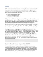
A subscriber who was connected to a manual switch would crank a lever to
electronically send an alerting signal that lit up a bulb on the operator's
switchboard. The operator would then connect her telephone to the calling line,
and ask for the called number. Next the operator would connect her telephone to
the called line, where she would place a ringing signal. If the called party answered
the call, the operator would establish the connection by plugging in a cord between
the two terminal jacks on the switchboard. Figure 1-1
shows this process; on the
switchboard, each terminal jack represents a subscriber.
Figure 1-1. Simple Call Setup Via a Manual Operator with Automatic Equivalent
[View full size image]
Signaling, as we know it today, began around 1889 with the invention of the
Strowger exchange (which was patented 1891). The Strowger exchange was an
electromechanical device that provided automatic switching using the simple idea
of two-motion selectors for establishing calls between two subscribers. It was also
known as a step-by-step switch because it followed pre-wired switching stages
from start to finish.
Inventing the Strowger Exchange
Almon B. Strowger was a schoolteacher and part-time undertaker. His
reportedly constant feuds with manual switchboard operators inspired
him to develop an automatic switching system and the dial telephone so
he could bypass manual switchboard operators [102
]. One reported feud
concerned an alleged business loss resulting from the complete lack of
privacy offered by a manual exchange. Strowger claimed that an
operator at the new manual exchange in Connecticut had intentionally
directed a call to a competitor—an allegation that gave rise to tales that
the operator was either married to or was the daughter of a competing
undertaker. Strowger moved from Topeka to Kansas City, where he
hoped his new, larger funeral home would earn him his fortune.
However, he suffered a similar fate there; he believed that the manual
operators there were intentionally giving his customers a busy signal.
Strowger therefore decided to do away with operators; he hired several
electromechanical technicians, who created the first automatic exchange
within a year. As a result, the telephone became faster, easier to use, and
more private for everyone.
The first Strowger exchange in the United States opened in La Porte,
Indiana in 1892 and had the switching capacity for ninety-nine lines.
Lobby groups protested at the automatic exchange, and one lobby group
championed the personalized service afforded by manual exchanges. The
lobby group did not have much success, however; manual switchboards
could not service the dramatic increase in telephone subscribers. By
1900 there were 1.4 million telephones in the United States.
In Great Britain, the first Strowger exchange opened at Epsom in Surrey
in 1912. The last Strowger switch was not removed from the British
Telecom (BT) service network until June 23, 1995, when it was removed
from Crawford, Scotland.
Strowger sold his patents to his associates for $1,800 in 1896 and sold
his share in the company for $10,000 in 1898. He died in 1902. In 1916,
his patents were sold to Bell Systems for $2.5 million dollars.
Strowgers' dial telephone is considered the precursor of today's touch-tone phone.
It had three buttons: one for hundreds, one for tens, and one for units. To call the
number 322, the caller had to push the hundreds button three times, the tens button
two times, and the units button two times.
In 1896 the Automatic Electric Company developed a rotary dial to generate the
p
ulses. This method of transmitting the dialed digits became known as pulse
dialing and was commonplace until the latter half of the twentieth century, when
tone dialing became available. See "Address Signals
" in the "Subscriber Signaling"
section of this chapter for a discussion of pulse and touch-tone dialing. It is
interesting to note that early users did not like the dial pulse handset because they
felt they were doing the "telephone company's job."
Even in Great Britain in 1930, the majority of all local and long distance calls were
still connected manually through an operator. But gradually, calls placed between
subscribers served by the same local switch could be dialed without the help of an
operator. Therefore, only subscriber signaling was required because an operator
would perform any inter-switch signaling manually. In the decades that followed, it
became possible to dial calls between subscribers who were served by nearby
switches. Thus the requirement for network signaling was born. Most large U.S.
cities had automatic exchanges by 1940.
Direct Distance Dialing (DDD) was introduced in the United States in the 1950s.
DDD allowed national long distance calls to be placed without operator assistance,
meaning that any switch in the United States could route signaling to any other
switch in the country. International Direct Distance Dialing (IDDD) became
p
ossible in the 1960s, thus creating the requirement for signaling between
international switches.
From 1889 to 1976, signaling had three main characteristics, which resulted
because only basic telephone services were available [102
]:
• Signaling was fairly simple. All that was required of the signaling system
was the setting-up and releasing of circuits between two subscribers.
• Signaling was always circuit-related; that is, all signals related directly to the
setting-up or clearing of circuits.
• There was a deterministic relationship, known as Channel Associated
Signaling (CAS), between the signaling and the voice traffic it controlled.
The "Channel Associated Signaling
" section of this chapter discusses CAS.
1976 to Present Day
Another form of signaling was introduced in 1976: Common Channel Signaling
(CCS). The "Common Channel Signaling
" section of this chapter further explains
CSS.
CCS has been used to implement applications beyond the scope of basic telephone
service, including Intelligent Networks (INs), supplementary services, and
signaling in cellular mobile networks. As you will learn, SS7 is the modern day
CCS system that is used for network signaling. As with any technical subject,
signaling can be split into a number of classifications. The broadest classification is
whether the signaling is subscriber or networked signaling. The following sections
discuss these types of signaling.