Smart Home Automation with Linux- P3 docx
Bạn đang xem bản rút gọn của tài liệu. Xem và tải ngay bản đầy đủ của tài liệu tại đây (838.41 KB, 30 trang )
CHAPTER 1 ■ APPLIANCE CONTROL
43
■ Note You may need an IR bypass kit when passing IR signals over coax cables because the messages get
muddled when passing through distribution amplifiers.
IR-RF-IR Gateways
These devices relay IR data through the air, at the 433MHz radio frequency used by so much wireless
equipment, before being replayed. For these devices, you have a choice between IR-only transmissions
and TV senders.
An IR-only transmitter, such as the Powermid XL, is the simplest of these devices and will allow you
to remotely control devices without installing cables or sockets. They are fairly cheap but pass only IR
data, so the controlled device must be able to have an impact on you when you’re in another room.
TV senders are the wireless versions of the over-the-aerial cables or old TV distribution systems,
which involved an aerial amplifier and a separate aerial cable into each TV in the house. The TV sender
takes a single input and transmits it to whichever receivers are listening, encoding whatever IR signals it
also saw. There are many variants on the market, including those with SCART sockets (instead of the old-
school coaxial aerial sockets) and RCA composite video. Even the cheaper models often have a
“channel” switch on them, allowing multiple receiver-transmitter pairs to be used in the same house
without the signals getting mixed up. And with these devices becoming more mainstream, some are
almost as cheap as an IR-only transmitter, with the TV functionality becoming a free bonus feature.
IR Over IP
It is also possible to send data over your existing Ethernet cables, using devices such as the Keene IR
Anywhere over IP (KIRA). This eliminates any distance or interference issues you might get from the
other methods and also provides a way of remotely controlling IR devices from a computer, without
needing to have the computer and its IR transmitter physically in range of the device.
Being IP-controlled also means that IR signals can be sent via the Internet. Although this is pointless
in itself (because you can’t derive any benefit from changing the TV channel when you’re not sitting
watching it), it does provide an off-the-shelf way of controlling IR-based devices from a remote
computer. And if something can be controlled from a computer, then it can be controlled from anything
connected to the computer, such as a web page or cron job.
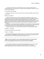
Using KIRA to retransmit IR codes first requires that you teach it those codes in the first place. This
is done by generating text files, using the software shown in Figure 1-15.
CHAPTER 1 ■ APPLIANCE CONTROL
44
Figure 1-15. Configuring KIRA
This software is available from the Keene web site
15
and has been thoughtfully written in Java,
making it Linux-friendly. After attaching KIRA to your network and after it’s used your DHCP server to
provide it with an IP address, you can add new commands. First you request that all the IR messages are
15
See www.keene.co.uk/electronics/multi.php?mycode=KIRA.
CHAPTER 1 ■ APPLIANCE CONTROL
45
sent to this machine, and then you press Learn before hitting the first key on your remote. This should
present the code, such as the following, which can then be copied and pasted into a text file for later use:
K 240C 037F 0369 03AC 034D 0624 035A 0378 0382 0378 0381 0396 0366 0377
0382 0396 0365 0396 06E0 03AF 034C 072C 0353 0378 2000
I have used a directory hierarchy for each device so that the on/off button for my TV is in the
directory ir/tv/codes/on. Since the same button performs both functions, I created a symlink between
off and on. Those with bigger houses and more TVs might like to use a more descriptive name than TV.
Although KIRA has a web page, it isn’t very configurable and limits you to four prestored IR codes.
Fortunately, it also listens for commands sent on UDP ports 30303 and 65432. The former is for device
discovery and configuration, so consequently the port cannot be changed. The latter is the IR control
port, which processes all the basic commands to control the various IR devices within range. All
responses to these commands are returned by UDP also, so you need to run two instances of the Swiss
Army knife of network utility, netcat, to handle it.
Begin by creating two terminal windows, and start a UDP server in one of them by typing the
following:
nc -u -l -p 30303
This will now listen on port 30303 for any UDP messages sent to it. Now, in the other window, send a
message to KIRA (whose IP has been determined as 192.168.1.111 by the DHCP server) on the same port.
echo disD | nc -q 0 -u 192.168.1.111 30303
You should see the other window spring to life and report various stats about the device. If not,
check that the ports are open and working with (that other Swiss Army knife of networking) netstat:
netstat -ntpl
With some averagely clever bash coding, you can achieve the same result with a script such as the
following:
#!/bin/bash
TEMPFILE=`mktemp`
nc -u -l -p 30303 >$TEMPFILE &
PROCESS=$!
echo disD | nc -q 0 -u 192.168.1.111 30303
# Wait for a second so the output has finished writing
sleep 1
kill $PROCESS
cat $TEMPFILE
rm $TEMPFILE
CHAPTER 1 ■ APPLIANCE CONTROL
46
The process for sending IR messages is the same, except you need to switch onto the IR port. Here’s
an example:
cat ir/codes/tv/off | nc -q 0 -u 192.168.1.111 65432
The only response sent to port 65432 is ACK, which can be safely ignored. However, if you do decide
to listen to port 65432 (and you have requested that all IR messages are forwarded to your PC), then you
will see the key codes appear. These can be copied from the terminal window (instead of using the web
interface) into your own configuration files. There is a supplied API document detailing each of the
commands that each port handles. Note that by using your Linux machine to maintain the IR codes, you
don’t need to ever upload keycode files to one of the four slots on its web server.
■ Note You can several KIRA devices on your network, each transmitting messages to different devices, although
for KIRA to receive messages and send them back to a PC, you must explicitly enable the functionality from its
web interface and give it the IP address where
netcat, or similar, will be listening.
IR Control
If you have a PC fairly close to the IR devices you want to control, it is easy to add a suitable USB-based
transmitter or receiver to it. These can be either bought from places like RedRat or built from one of the
circuit diagrams provided by the LIRC (Linux Infra-Red Remote Control), which also provides the
software.
■ Caution Most PCs attach USB ports directly to the motherboard, and if you make a mistake when building your
own device, you could destroy it. Purchasing a separate PCI board with USB sockets should provide some
protection from mishaps.
For IR transmission, you need to know the specific control codes of the device you want to control.
If you have a standard TV or video, this data is usually available online
( otherwise, you will also need to purchase or build an IR
receiver to teach LIRC the existing codes. Fortunately, if you took the earlier hint and bought a RedRat,
you will have a receiver built in that, along with the supplied Windows software or LIRC, can be used to
program the codes directly.
LIRC
16
is the Linux-standard method for reading and transmitting IR data. It comprises a standard
daemon, lircd, and a set of tools to record the input messages and transmit them back again. It adopts a
16
CHAPTER 1 ■ APPLIANCE CONTROL
47
modular approach to support the wide variety of LIRC devices available. Reproducing an installation
guide here would be foolhardy, but suffice to say there are three main types of supported control:
GPIO devices: These are generally supplied with TV cards, such as those from
Hauppauge. The modules are usually compiled into the standard daemon
build.
Serial port device: This covers a wide range of different devices, including
home-brew transmitters, and because they process serial data directly, they
don’t need any specific driver code. Typical circuits are available from the LIRC
web site. If you’re unsure about connecting your own electronics onto your PC
motherboard, you can buy serial PCI cards, which offer a level of protection
against rogue electronics.
Kernel drivers: These, such as the RedRat3 device, require you to build LIRC
from source and (in some cases) copy the new driver code into the LIRC
directory. From here you can rebuild the setup (data2setup.sh) file and build as
normal. These devices will make use of the /dev/lircd device, which should
have ugo+rw privileges.
Once built, the drivers can be configured and prepared according to the table at LIRC,
17
which also
provides sample configuration files for the various devices that describe each button with a human-
friendly name and the details of the IR signal to be sent. From here, you can add specific commands to
be triggered upon the various button presses within the .lircrc file, which has a format typical of this:
begin
prog = mythtv
button = Rew
config = Left
end
Each button on the remote is mapped to a function of the software (prog) in this fashion.
One of the big benefits in using RedRat, and LIRC in general, is its inclusion in many standard media
players, mixers, and TV applications. Consequently, if this is your primary purpose of IR, then you have
completed your media installation already since those commands can trigger something useful in the
existing software!
LIRC also has a network mode whereby you can communicate with an LIRC daemon through a
network socket, allowing an external application to act as if it were a local IR remote control. This is
useful for testing and as a method of remotely a PC-based media player without writing new code.
For more specific applications, you will need to make use of irexec, as shown here:
begin
prog = irexec
button = ok
config = /usr/bin/someprogram with arguments here
end
17
www.lirc.org/html/table.html
CHAPTER 1 ■ APPLIANCE CONTROL
48
In this way, you can use an IR remote to interact with other arbitrary applications, including media
players on other machines. Additionally, you can adopt the same ideas as Cosmic (mentioned earlier
and covered in Chapter 7) to develop a state-based control mechanism using very cheap IR transmitters.
Conclusion
Each device in your home should have the ability to be controlled remotely, either through the power
lines (with X10 or C-Bus), with an Ethernet socket, or through basic Infrared. This is the first step of a
two-stage process. The second is when you have a computer able to issue control messages to those
devices. At that point, they can be used seamlessly from anywhere in the world. When the device doesn’t
support such functionality, you have to hack it. And that’s where the geeky fun begins!
C H A P T E R 2
■ ■ ■
49
Appliance Hacking
Converting Existing Technology
There are three classical forms of hacking: software, hardware, and wetware (also known as social
engineering). More recently, firmware hacking has become prominent because low-cost hardware
utilizing embedded Linux has opened the door to software hackers unable to build hardware. It is
hardware hacking, and its associated software, that I will cover in this chapter.
Software Hacks
For most developers, software is an easier hack, since the chance of breaking something irrevocably is
much reduced compared to hacking hardware. In fact, when Steve Wozniak and Steve Jobs were
building machines at the Homebrew Computer Club, they reasoned that for every one hacker who was
interested in hardware, there were 100 who were keen on software, so they focused on the software
capabilities of the Apple computer.
Linksys NSLU2
This device, also known as “the Slug,” is a small, embedded Linux device intended to function as a
network addressable storage (NAS) device. You plug in power, a network cable, and (up to) two USB
hard drives, and you’re able to retrieve the data stored on it from any machine on the same network
subnet using the Samba protocol.
The machine itself is silent, powered by an Intel XScale IXP420, and incorporates 32MB of SDRAM
and 8MB of flash memory where the software is stored. Its low price point and openness of firmware
makes it attractive to hackers wanting to add or change the software on the machine. The machine was
officially discontinued in 2008 but is still available in various stores and online.
In its intended form, the Slug is a suitable machine when only a file server is needed, either to be a
remote backup for desktop work (perhaps located under the stairs or in a loft) or to provide music to
media players around the house. By changing its firmware, however, it can become the following:
• Web server (Apache, PHP, Perl, and Python are all supported)
• Mail server
CHAPTER 2 ■ APPLIANCE HACKING
50
• Printer server (the cost of a Slug can be less than the difference between a USB
printer and its networked equivalent)
• Media server (shared through Squeezebox Server, iTunes, or just Samba)
Before any software changes take place, you must first install an unrestricted version of Linux into
the firmware of the device, which takes place through its built-in web interface. There are two main
variations here: Unslung (which uses Optware packages) and SlugOS (formally called OpenSlug) based
around OpenEmbedded.
Unslung
For basic improvements and a minimal of fuss, Unslung (www.nslu2-linux.org/wiki/Unslung/HomePage)
is the preferred option because it installs over the top of the existing firmware and appears very similar
to the end user, since it is based on the original Linksys code. This firmware provides extra functionality
such as the ability to use FAT-formatted disks, which is necessary if you want to use an existing hard
drive, since any disk used in the Slug needs to be specially formatted (to ext3) before use.
It is also possible to install extra software packages through Optware using commands like the
following:
ipkg install apache
However, you need to be careful since they are installed to the internal flash memory, which can run
out very quickly and therefore lead to an unbootable device. To prevent this, you need to move the
operating system onto either one of the external drives (either a USB memory stick or an entire hard
drive, depending on the scope and size of your intended additions) in a process known as “unslinging
your Slug.” Alternatively, you can perform a hardware hack to increase the memory.
Several hundred packages are available for an unslung Slug, including the following:
• BitTorrent clients
• Streamers for Xbox Media Server
• Apache web server
• Asterisk VoIP
• CUPS
• Git
• MySQL
• SSH
As you can see, most major packages are available, making this a very low-power machine, capable
of providing most home tasks. However, they are all limited by the 2.4 kernel, so for more exotic
hardware (like Bluetooth), you will need to adopt SlugOS.
CHAPTER 2 ■ APPLIANCE HACKING
51
SlugOS
SlugOS is a much larger endeavor and treats the Slug like any other piece of hardware, with a base
operating system and separate packages for the main functionality, fitting in with the traditional Unix
ideology of “do one thing and do it well.” This also removes the Slug-specific functionality such as the
web-based configuration tool and basic services like Samba that you will consequently have to explicitly
install.
If you are using the Slug as the basis for a much larger home automation server, then this provides
greater scope in the upgrade path, because it gives you access to the many thousands of packages
provided by the OpenEmbedded project on which SlugOS is based. But doing so requires that you
devote some, or all, of one of your connected hard drives to the operating system, which is a process that
requires you to install a small system into the flash memory and then bootstrap the operating system
onto the hard drive. In doing so, SlugOS permits the use of a 2.6-based kernel, as well as RAID and NFS
functionality.
When using an external USB drive to hold the operating system, always use a hard drive (as opposed
to a memory stick). This is because some applications (such as MySQL) create a lot of memory writes to
the swap file, and since flash memory becomes unusable after about 100,000 writes, this can happen
sooner rather than later. You could, alternatively, assign the swap file to a second (hard) drive, allowing
the operating system to boot and run from a read-only memory stick.
Developing on the Slug
To write your own software for the Slug, you should start with SlugOS because this gives you access to
the standard development tools, which run on the device allowing the code to be written, compiled, and
tested on the Slug. This is known as native development. First you need to run the following command,
along with the other standard build packages (all detailed at www.nslu2-
linux.org/wiki/HowTo/SlugOSNativeCompileEnvironment), before developing your code as normal:
ipkg install slugos-native
Without a screen, however, you will not be able to use GUI debuggers such as kdbg, which can be a
scary downgrade for some. It is perfectly possible to run the machine headless, however, since you can
connect remotely through ssh or telnet. This is preferable since the speed of the machine makes a GUI
approach impractical for large applications. You would more likely write and test your application for
your desktop machine and then, when it’s ready, cross-compile for the Slug.
Cross compilation is a process whereby a compiler running on machine A is able to produce code
suitable for machine B. To do this, you need a new set of compilers, tools, headers, and libraries (known
together as the toolchain) that are built purposely for the other architecture. These are stored separate
from your existing development files since they would otherwise conflict with those running your
machine. The compilation process then occurs as normal (through either make or a variant of gcc, such
as armeb-linux-gnu-gcc) to produce a suitable executable file, or elf in Linux parlance.
The best introduction for the installation of these tools is at www.nslu2-
linux.org/wiki/DebianSlug/CrossCompiling.
Note that if you’re using only existing packages, compilation tools are not necessary in any form,
and you can rely solely on the prebuilt packages.
CHAPTER 2 ■ APPLIANCE HACKING
52
Hacking Game Consoles
Game consoles are great for playing games. Old game console are great for playing old games—and
hacking into Linux machines! As the previous generation of machines becomes cheap and
technologically obsolete, old game consoles provide a good embedded platform for media players, web
servers, control units, and the like. In this section, you will learn primarily at how these machines can be
bent to your will, rather than specific uses for them.
It is not smooth sailing, alas, because the manufacturers do not make the compilers or development
environments available to anyone outside the computer games industry, and even then it is only with
strict nondisclosure agreements (NDAs).
1
Although this should be enough to satisfy an overzealous legal
department, they then build in security measures to make it difficult to run home-brew code on them by
encrypting the disc format, BIOS, or executable. This in itself makes it an interesting problem for
hackers. And since most manufacturers lose money on the console (knowing they’ll recoup it on the
games), the subversive hackers enjoy this process even more.
Despite the ever-decreasing circles of cost, it is not worth buying a new console for the sole purpose
of hacking it into a Linux machine, but charity shops and online auctions can provide the hacker with
the previous generation of hardware at a cost that makes the time and geek-cred worthwhile. With all
technological challenges, however, the interest of those leading these console-hacking projects tends to
wane as newer and more powerful machines become available or as the time benefit outweighs the cost
of alternative equipment. Therefore, it is likely that some (or all!) of these projects might have fallen out
of favor by the time you read this, as the Xbox 360 becomes old hat and the PlayStation 4 is the current
console du jour.
Sega Dreamcast
The Dreamcast was a game console released in 1998 in the wake of the ill-fated Sega Saturn. It was the
winner of an internal competition in Sega between two teams of engineers, led by IBM researcher Tatsuo
Yamamoto and Sega hardware engineer Hideki Sato. The resulting console featured elements from both
designs and was based around a 200MHz Hitachi SH4 RISC processor and the PowerVR2 graphics chip
from VideoLogic, which is fast enough for video playback.
It also featured an optical GD-ROM drive, which supported a standard CD-ROM partition (on which
the OS was included), as well as a proprietary format section for the game. The console also marked
Microsoft’s first exploration into the hardware arena by combining the Windows CE OS with its DirectX
technology.
The console also included a visual memory unit (VMU), which in addition to being a basic memory
cartridge also featured an 8-bit process, 48 ×32 pixel LCD screen, D-pad, and four basic buttons. It was
intended to be used as an auxiliary play device, rather than a handheld console in itself, and needed to
be plugged into a controller in order to function. It was a good idea (and one reused by Sony years later
with its PocketStation device, which also featured IR control), but it was not powerful enough for any
significant work, compared to the equivalent technology at that time.
Sega was also ahead of the curve by providing peripherals for the Dreamcast such as a mouse,
keyboard, and Ethernet (known colloquially as a broadband adapter, or BBA). The latter two are
considered essential for the installation and use of Linux.
1
An NDA is a legal document formed by companies to prevent you from talking about their technology or ideas with
anyone else.
CHAPTER 2 ■ APPLIANCE HACKING
53
LinuxDC () is an old—almost defunct—project that has recently
seen a small spurt of new life. It is a reasonably complete distribution suitable for web browsing (with a
BBA), movie playback, and emulation. This itself is a good hack, but there are also cables to provide two-
way serial communication, either between the Dreamcast and a PC or between peripherals such as
infrared (IR) transmitters and receivers. You can either build this cable yourself using one chip and three
capacitors from the circuit shown at or purchase a similarly
compatible cable, which is known as a DC coders cable.
There is also Dreamcast emulation software for Linux called LXDream, which provides a quick way
to verify the working, or not, of various Dreamcast software hacks. You can find this at www.lxdream.org,
which also provides all-important links to prebuilt disc image ISOs of LinuxDC, from
www.lxdream.org/wiki/index.php?title=Dreamcast_Linux.
■ Note Emulators such as LXDream require an image of the machine’s original BIOS. Since these are usually still
under copyright, they are not packaged with the emulator and must be extracted from a machine (that you legally
own).
In addition to these, there are various pieces of stand-alone software that can be cross-compiled
and uploaded via the serial DC coders cable to the Dreamcast. Some of these are shown on the pages at
This includes example source code for text, graphics, sound, and serial
communications. By avoiding an operating system, you can make better use of the comparatively small
16MB of memory and 200MHz processor, at the expense of ease of development.
Sony PlayStation
Sony is now promoting its third generation of PlayStation console, imaginatively titled PlayStation 3
(PS3). It is still too new to make it financially viable to turn the whole machine into an home automation
device (and since it’s a very capable media playback device already), but you can install Linux on it if you
want. (Note that the Slimline version of the PS3 does not support this.) For software engineers, it is a
good platform to learn the CELL architecture, but since the kernel isn’t optimized for this chip, the
operating system is comparatively slow, meaning the same money and electricity could be put to better
use with a standard PC. However, the newness of this machine means there are two older consoles being
neglected that can be had for very little money.
PlayStation 1
The first PlayStation released in 1994 (now referred to as the PlayStation 1, to differentiate itself from the
PlayStation brand) had a mere 2MB of RAM, a 33.8MHz CPU, and no memory management unit (MMU),
meaning that only the uClinux kernel was suitable for porting, but even then converting the rest of the
system was difficult. Only one installation seems to have existed, Runix (originally called PSXLinux),
although this is now near impossible to find. This is no great loss because, unlike modern game
consoles, it didn’t have a hard drive, which limits its use as a Linux machine.
Instead of using existing Linux software, it is still possible to develop applications from scratch using
Net Yaroze and utilizing the 128KB memory card for temporary storage. This comprises a black
PlayStation, controllers, cables, software, and manuals for software development, and it was intended to
CHAPTER 2 ■ APPLIANCE HACKING
54
get hobbyists into the field by providing a means of compiling software on a PC and uploading it through
the serial cable—which was also used for debugging—to the PlayStation. The machine was sold via mail
order and to universities but wasn’t a big success. Ultimately, there aren’t many of these devices
available, so they’re mostly traded between enthusiasts for excessive money. However, the speed of the
machine makes it unsuitable for video playback,
2
and its lack of communication ports further limits its
potential.
A much better use for the PlayStation 1 is not as a computer but as a CD player, especially the first
versions. This is because the original console had a much improved DAC inside it over later versions,
giving it professional audio quality output when playing CDs. This model can be distinguished by the
model number SCPH 100x and the separate audio and video RCA outputs.
PlayStation 2
Sony’s second machine was released in 2000 and called the PlayStation 2 (you might detect a naming
pattern here!), and it provided a significant increase in power over its predecessor. It had 32MB of RAM
and contained separate chips for I/O, sound, and graphics, and it had a main CPU called the Emotion
Engine (running at 294.9MHz or 299MHz depending on whether it was an original or later device). This
made it a more realistic specification for Linux. Furthermore, an easy route for doing so was provided by
Sony, which sold its own supplementary kit, called PS2 Linux. It provided the end user with a hard drive,
a keyboard, mouse, an Ethernet adapter, and the necessary software and manuals to develop software.
These kits are no longer sold or supported, but some are available from old stock and from secondhand
dealers. Development is much easier on the eye if you ignore the TV output and use a monitor—you’ll
need one that does sync-on-green. The supplied distribution is ultimately based on an old version of Red
Hat with a 2.2.x kernel, although newer versions now exist, along with Mozilla, XChat, and various
lightweight GUI applications; utilities that make use of the USB ports such as printers and cameras; and
the network port. Before you take this route, check the current range of available software and kernels at
.
Outside of the official Linux distribution, there is a wide selection of home-brew software, such as
media players and emulators. You can download them as elfs from sites like or
www.exploitstation.com, or you can build them yourself on a PC using a set of cross-compilation tools
and run from a disc, memory card, network, or USB memory stick.
Persuading a PS2 to run nonapproved software is no longer difficult, because several software-only
exploits have been discovered, along with the hardware hacks where a so-called modchip is physically
soldered into the computer itself.
One soft hack is called the PS2 Independence Exploit, where a disc from a PlayStation 1 game is
used to load a special file from the memory card, which in turn triggers a buffer overrun allowing
unsigned code to run. This is explained in detail at
Free McBoot () is a newer soft hack, which also allows you to run
home-brew software by installing special software tied into the specific memory card. It also works on
Slimline PS2s and most newer machines (unlike the Independence Exploit), with the only currently
known exceptions being those with a date code of 8c and 8d (BIOS Version v2.30).
In addition to the sites listed, several video-sharing web sites include visual tutorials describing the
process. And as always, you may be able to find suitable modchips for hardware hacking.
2
The codecs now in use require more CPU power than the formats used in games of that time.
CHAPTER 2 ■ APPLIANCE HACKING
55
PlayStation Portable
There is one final PlayStation product to mention, the PlayStationPortable (PSP), which was released in
2004 and is based on the PS2. This is a handheld device and benefits the HA hackers with 802.11b WiFi
connectivity. IrDA is also featured on the older PSP-1000 models, with the newer version (PSP Go)
supporting Bluetooth. All have dual MIPS R4000 chips running at 333 MHz
3
and 32MB of RAM, making
them more than capable devices.
Like most consoles, however, the PSP has been designed to run only signed code created by Sony,
thereby eliminating its ability to be a programmable computer in any real sense. And, like most
consoles, hackers found ways of circumventing this, by exploiting an issue in the original 1.5 firmware.
This ultimately led to a cat-and-mouse game of firmware upgrades by Sony to close these loopholes (and
bribing users to upgrade by including new features like web browsers) as the hackers attempted to
reopen them or work out ways of downgrading to 1.5 (without triggering the Trojan code that Sony had
placed in the firmware, which would “brick” your machine) to use the old exploit.
A wide range of home-brew software is available for PSP including the YouTube viewer PSPTube
and a control application for the Xbox Media Center; a good source is
However, one of the real benefits of this device is that you don’t even need to hack it in order to install a
web browser, since (from version 2.0) the NetFront Browser has been included by default, and from 3.90
it has included Skype for VoIP calls. Since most home automation equipment comes with a web server
or one can be written fairly easily, a web browser is enough for a fairly high level of home control.
■ Note If you plan on using custom or cracked firmware to run home-brew software, always do it early in the
device’s ownership life cycle. That way you won’t lose any personal data if something does go wrong in the
firmware update process.
Microsoft Xbox
Like the Sony PlayStation 3, Microsoft’s current game console—the Xbox 360—is probably too new and
expensive to be worth hacking into something else, although many people have worked on the problem
and created the www.free60.org project in doing so.
The Xbox game console was introduced in 2001 and was probably the first time many people
considered the possibilities of using a (near-)standard PC connected to their standard TV. This was no
doubt helped by the knowledge that Microsoft was using its Windows and DirectX technologies in the
unit, both of which were well known, thus presenting a very low barrier to entry for the hackers.
As a unit, the Xbox is based around a 733MHz Pentium III chip with 64MB of RAM, along with a
DVD-ROM and a 10GB hard drive—the only last-generation console to do so—by default. It also has
Ethernet support and USB ports but with a proprietary form factor and wiring. This remonstrative
oversight caused many companies to generate business plans based solely around the sale of Xbox USB
converters, of which there are many!
3
Firmwares prior to 3.50 are underclocked at 222MHz.
CHAPTER 2 ■ APPLIANCE HACKING
56
As a physical unit it is quite large (320 ×100 ×260 mm) and has a fairly noisy fan, although hardware
hackers might be able to squeeze this down to laptop size and replace the fan with a silent one. In any
case, you will certainly want to locate the machine away from your ears and the speaker system in use.
Running Linux
There is a perverse geek pleasure in running Linux on Microsoft’s first flagship console. Furthermore,
because we’re coming in at the end of its life cycle, any breakages, void warranties, or bricked machines
are less important to us than they would have been a few years ago. Also, the hacker community has had
enough time to improve the hacking process so that even those scared of soldering irons can do it
without fear. The primary site is www.xbox-linux.org.
■ Note Although all Xboxes are capable of running Linux, there are many issues with version 1.6 since the BIOS is
no longer stored in a chip that can be (re)flashed. This chip, known as a thin small outline package (TSOP), is
instead hardwired, requiring the use of an extra hardware modification chip loaded with the Cromwell Linux BIOS,
and even then the output resolutions possible are much reduced (only composite and S-video with overscan, and
up to 480p HDTV) because of the different graphics hardware in use. You can determine the version number with
the chart at
www.xbox-linux.org/wiki/Xbox_Versions_HOWTO.
As is usual with console hacks, there is a hardware way to do it and a software way. The hardware
way involves the purchase and soldering of a modchip; although their use has questionable legality,
4
this
provides the most expansive scope for hacking since you can do the following:
• Increase the hard drive size (but less than 137GB is still recommended)
• Replace the DVD with another hard drive or DVD-RW
• Use all the disk space under Linux
After fitting the chip, you need to trick the Xbox into running code that allows you to make use of it.
This is done through an exploit, such as the MechAssault Exploit, which uses broken code within the
game and a well-crafted save game file, at which point you can transfer arbitrary data onto the Xbox
(through the network) and run an application to flash the BIOS with it. The process is simple but fiddly,
since you need adapter cables, the correct version of the game, and a separate machine. As mentioned,
this is the only (relatively) safe way of introducing Xbox Linux to a version 1.6 machine.
The downside of a hardware hack is that the online component of Xbox games (in other words, Xbox
Live) are unavailable, since Microsoft will ban anyone found using Linux on its machine.
The software hack involves most of the same steps, with the few added complications explained in
detail at www.xbox-linux.org/wiki/Software_Method_HOWTO. Naturally, being software, the Linux install
4
Some cite contravention of the DMCA/EUCD, and some cases have been dismissed.
CHAPTER 2 ■ APPLIANCE HACKING
57
disappears on each reboot—your data remains, but you must reinstate the hack to boot Linux in order to
access it.
There was once The Xbox Chocolate Project, where Xbox Linux users would help would-be users
modify their machines. It is still going, but fewer volunteers are available. Asking at your local Linux User
Group (aka LUG; see www.linux.org/groups for your local group) might be another idea.
The reason for hacking an Xbox is up to you. If you just want to make it play DVDs, then the
Microsoft DVD Playback Kit is a better option, and it comes with its own IR remote control. As a set-top
box, it might be a little noisy compared to the other solutions I’ve mentioned (and will mention) by
today’s standards. But as a secondary (or even primary) file server, web server, or even desktop machine,
it has extremely positive geek credentials.
Xbox Media Center
Despite the name, there are more versions of Xbox Media Center (XBMC) running on non-Xbox
platforms than there are on the Xbox, including Live CD, all available from www.xbmc.org! This is because
the software can only be compiled using the Xbox development kit (XDK), which is made available only
to licensed developers. And since Microsoft isn’t happy with Linux developers writing open source
software on its console, this is not available to hobbyists in any form. Consequently, the only native
versions of XBMC running in the wild are those compiled by licensed developers and those versions that
have leaked out from those developers. The legality of such versions is seriously suspect. In either case,
you will still need a modified Xbox to run the code, as you would with Xbox Linux.
■ Note If you do have access to the Xbox software, then you can use the IR remote control that is supplied with
the Microsoft DVD Playback Kit with XBMC.
As software, XBMC contains a lot of top-end functionality and is still in active development. This
includes an initiative to reduce the boot time, making it appear more like a set-top box and less like a
computer running software—one goal to which all home automation devices should aspire.
Its functionality includes the ability to play back media of almost every format (coming from hard
disks, optical media, network shares, online streams and feeds, and DAAP for iTunes), display
photographs, run Python-written plug-ins (for weather reports and the like), and play games. It is also
able to support the media with data services from IMDb (the Amazon-owned Internet Movie Database)
and FreeDB (for CD track listings). For many, the main XBMC hackjoy concerns its skinnability, allowing
anyone with a minimum of knowledge to create custom interfaces for the software.
Despite its prominence, there are several forks of XBMC: Boxee, with integration into social
networking applications; MediaPortal, a Windows-centric version with PVR handling; Plex, which
focuses on the Mac OS X and associated Apple platform-oriented functionality (such as the iTunes app
store); and Voddler, which supports media streaming from its (commercial) video-on-demand site.
CHAPTER 2 ■ APPLIANCE HACKING
58
Hardware Hacks
The hacks in this category will involve changes you can make either to existing hardware or to new
hardware you can easily build that controls, or is controlled by, an existing computer.
Linksys NSLU2
The existing NSLU2 unit (aka the Slug) requires no hardware hacks to make it run any of the custom
Linux firmwares covered earlier. However, you can improve the unit with various hacks.
Always On
Like most consumer hardware, the Slug has an on/off button. For normal operation, this is fine. But for a
home automation system, which is generally intended to work 24/7 (like the rest of the house), this can
cause problems whenever there is a brief power outage, since the machine then needs to be manually
switched back on. Also, if you are controlling the Slug’s power remotely, maybe through a timed X10
appliance module or stand-alone timer, it won’t fully turn on since it needs the button to be pressed.
In the first instance, there are obvious solutions here, such as putting the Slug onto a UPS or keeping
it accessible so you can manually control it. However, these negate the benefits of it being cheap,
hidden, and (importantly for HA) controllable.
You can solve this by invalidating your warranty by performing one of several hardware hacks to
ensure the machine always switches on when the power is applied. These vary from using USB Y-cables
in various configurations to soldering components to the board. All are detailed, with their relative
merits online (www.nslu2-linux.org/wiki/HowTo/ForcePowerAlwaysOn).
Overclocking
Prior to 2006, all Slugs ran slower than necessary since their CPUs were clocked at 133MHz, despite the
chip being designed to run at 266MHz. This technically meant the original versions were underclocked,
which means the following hack is known as de-underclocking, rather than overclocking. If you log into
your Slug (through telnet or ssh, depending on your firmware) and type the following:
cat /proc/cpuinfo
you’ll see a BogoMIPS value, indicating the currently speed. If this is within 10 percent of the 133 value,
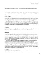
then you can improve the speed by removing the resistor shown in Figure 2-1.
CHAPTER 2 ■ APPLIANCE HACKING
59
Figure 2-1. The de-underclocking resistor (second from the bottom in the R84 stack). Image from
released under cc-by-sa.
You can remove it using nail clippers, a soldering iron, a saw, or any combination of the above. Just
be sure to not to damage any other components.
Serial Port
You can use a standard serial port for two-way communication between many pieces of old technology
such as joysticks, along with LCD text displays and other forms of home-brew electronics. It also
provides a way of controlling the Slug through getty when other routes, such as the network, are failing.
There is already a serial port hidden away at J2 on the Slug motherboard. Alas, its control voltages
are 0/+3.3v, and not the +/-12V necessary for the standard RS-232 serial port, which means you’ll require
a power-level converter. (However, strictly speaking, the standard requires hardware to differentiate
between voltages in the range of +/- 3–15V.) Some converters can be purchased as a single chip (such as
the MAX3232) or already included in some mobile phone data cables. You can find full details on the
web site (www.nslu2-linux.org/wiki/HowTo/AddASerialPort).
There are also circuits available that allow you to connect an LCD character display (such as the
HD44780) to the Slug with a minimum of effort, providing a basic (and very low-power) display to report
the current media playing or the machine status. However, this also requires opening your Slug to make
hardware adjustments. If you’d prefer, the Pertelian
5
plugs into the external USB and achieves the same
effect. It is supported through the standard software available in OpenSlug, thereby making this the
most effective way of having a display on the Slug available in a silent environment.
5
Being USB, this can also plug into any standard PC, or you could hack a PicoLCD or build one of the many circuits
on the Web (such as at
or
which converts a photo album key ring into a display device).
CHAPTER 2 ■ APPLIANCE HACKING
60
LEGO Mindstorms
First released in 1998, LEGO Mindstorms was originally known as the Mindstorms Robotics Invention
System (RIS) Kit and contained a control brick known as RCX to which you uploaded a program with
infrared. The software would then run, control the various motors and sensors connected to the RCX
brick, and communicate with others via IR. This naturally had the usual problems associated with IR as
covered in Chapter 1 (primarily line of sight). There were two versions of RCX released, and both
operated the IR at different carrier frequencies (although both RCX modules can transmit on either
frequency) but were functionality identical.
The programming could be done in many languages, including cut-down versions of Java, C/C++,
Lisp, and Forth, provided it was compiled into suitable code for the internal microcontroller, a Renesas
H8/300. Because of its age, it is now available fairly cheaply, although the supplied IR transmitter has no
support for any 64-bit operating systems and is losing support for newer 32-bit ones.
From RCX, LEGO moved to Mindstorms NXT in 2006. This increased the specification of the main
brick by improving the processor (now a 32-bit ARM7/TDMI chip) and communications devices (it now
included USB, Bluetooth, and an onboard 100 ×64 pixel LCD matrix). This upgrade in processor has
necessitated a change in control software, but that is to be expected, and most of the RIS code has now
been ported to NXT. The LEGO components also improved, as shown in Table 2-1.
Table 2-1. LEGO Mindstorms Specifications
Kit Motors Touch
Sensors
Light
Sensors
Ultrasonic
Sensors
Sound
Sensors
Color
Sensor
RIS 2 2 1
NXT 3* 1 1 1 1
NXT 2.0 3* 2 1 1 1
NXT Education 3* 2 1 1 1
* These are servo motors, which internally monitor their position for greater positional accuracy.
Since 2009, Mindstorms has been on its third iteration (NXT 2.0) and consists of the same RCX brick
as NXT version 1.0, some alternative LEGO Technic bricks, and a change in sensor from sound to color.
This was an odd change, since now all NXT 2.0 robots are deaf by default! This might have been a ploy to
sell more add-on sensors, however, but for the wily hacker, these can be made much more cheaply using
standard electronic components using instructions found on the Web or in various books, such as
Extreme NXT.
6
Where LEGO Mindstorms excels is its ability to rapidly prototype hardware that can be controlled by
the computer, as well as remote sensors that can relay information back to it. This provides a method
6
Formally called Extreme NXT: Extending the LEGO MINDSTORMS NXT to the Next Level (ISBN 978-1590598184)
CHAPTER 2 ■ APPLIANCE HACKING
61
whereby the computer’s state can be demonstrated by something in the real world. Similarly, it allows
the real world to be understood, to some degree, by the computer.
Home automation is full of ideas, and not all of them have the staying power to enhance your living
once their novelty has worn off. This makes LEGO perfect as a means of building proof-of-concept
hardware before devoting time and money on PIC chips, motors, and cases that will be used for only one
project. Here are some ideas:
• Create a robot that waves, or gestures, when an email, private instant message, or
phone call is received.
• Use the LCD on the NXT processor block to relay information, such as weather.
• Create a robot to open the fridge and bring beer into the living room.
7
• Create a Bluetooth gateway for sensors and devices around the house (for a cat
flap or pressure mats).
The handling of each sensor and motor is very simple since it’s simply a matter of programming,
using one of the available Linux environments, such as leJOS NXJ (Java for LEGO Mindstorms) or NXC
(Not eXactly C). There are books and web articles abound on the subject, including this useful start
point:
Arduino as an I/O Device
The Arduino and its clones are microcontroller boards that you can think of as grown-up LEGO—it
provides a simple way of interfacing the real world with the computer, handling basic processing tasks
on a chip (instead of in software), and working with hardware motors and sensors.
There are many forms of Arduino, based on simple microcontrollers, but the most common
development version is the Arduino Diecimila based on the ATmega168 chip, although this is being
superseded by the Arduino Duemilanove using the Atmega 328. It supports 14 digital pins that can be
configured as either input or output and 6 analog inputs. The missing part here is analog output, which
can be provided by using pulse width modulation (PWM
8
) on 6 of the 14 existing digital outputs or with
additional electronics. Power can be provided by the USB port, by a power socket, or by connecting the
wires from a battery clip to the board. An onboard jumper is used to switch between USB and external
power sources.
7
This is a difficult one to build, by the way, because the suction on most fridge doors is more powerful than the LEGO
motors.
8
PWM is where the digital output voltage is switched between high and low so that the average voltage, over time, is
somewhere between the two. Not all hardware can be powered like this, however, but it is a cheap compromise.
CHAPTER 2 ■ APPLIANCE HACKING
62
To those used to large machines, the specification of the ATMega168 chip appears rather small:
• 14KB of available Flash memory, for software
• 1KB of SRAM, for data
• 512 bytes of EEPROM, for permanent data; acts like a mini hard disk
• 16MHz clock speed
Even the ATMega328, with double the memory capabilities, seems less than adequate. However, the
tasks the Arduino will generally perform are very simple and usually in the realm of comparing various
inputs and performing simple logic, so this specification is more than large enough. The complex tasks
found in operating systems, like TCP/IP stacks, are not usually necessary since you can transmit
requests to a connected PC for these tasks. And when they’re not, the problem is generally solved in
hardware by building the appropriate circuit and including the necessary driver software for that
hardware component.
If you’re experienced with other microcontrollers or PIC chips, the Arduino isn’t different in any
technical way to them, so you can continue to use whatever chips you have used previously. However,
the Arduino offers many benefits to those less used to electronics:
• A C-based language and development environment, instead of assembler.
• USB input/output control as standard.
• A large community of hackers, publishing project designs and sharing tips.
• Robust development boards that are less likely to blow up if you wrongly connect
something.
• A wide range of prebuilt, compatible circuit boards (called shields) to provide
more complex functionality such as wireless communication. You’ll see some
examples later in the chapter in the “Arduino Hardware” section.
• And, for the purists, open source hardware and architecture. This is an often
overlooked point. Having the hardware open source allows clone makers, such as
Seeeduino, to exist. Clones can be cheaper and more robust and can use surface-
mount components while still remaining pin compatible with the Arduino and its
assorted shields.
The scope of possible projects is similar to that of the LEGO Mindstorms, although now the circuits
can be very much smaller, involving more discrete components and wider functionality achieved
through the aforementioned shields. Whereas a LEGO device might be able to beep or play a short sound
to indicate the arrival of an e-mail, the Arduino can use speech synthesis or full audio playback.
Installation and Setup
All Arduino software is written on a PC and transmitted to the board through USB. This is also used to
receive any data the Arduino chooses to transmit, by default through /dev/ttyUSB0. (Remember to add
your user into the dialout group so that /dev/ttyUSB0 is accessible.) The development can take place in
any fashion you desire, but it is simplest with the Java-based IDE. Even if you adopt a command-line
approach, the code will need to be compiled using the avr-gcc toolchain, which can be installed under
Debian with this:
CHAPTER 2 ■ APPLIANCE HACKING
63
apt-get install gcc-avr avr-libc avrdude
Java, if uninstalled, will need an extra line, like this:
apt-get install openjdk-6-jre
From here, it’s a simple matter of installing the IDE. This is provided as a single archive from the
web site at Extract this to an appropriate directory (root access is
not required for any of these steps), and run ./arduino from the directory. You should then set up the
appropriate USB device and type of Arduino (Tools
➤ Serial Port and Tools ➤ Board, respectively)
before use.
You can begin a project by selecting File
➤ New from the menu. This creates what the Arduino IDE
calls a sketch. This involves a subdirectory in the Arduino working folder and a primary source file. Other
source files can be added into the sketch (through Sketch
➤ Add File) and will be automatically included
into the project build. There is no Makefile equivalent here, and every file added to the sketch, even if it
is a library file from another directory, is copied into the sketch directory. Note that despite the visual
similarity to C code, all files are given the extension .pde for clarity.
Then verify the build, and if everything is working,
9
upload it to the Arduino.
■ Note You cannot create a sketch of a given name. Instead, you must create a blank new sketch and then select
Save As as a separate step.
The build process itself is handled behind the scenes using avr-gcc, a cross-compilation toolchain
for the Atmel AVR RISC processors, of which the ATmega168 is one. It creates a separate applet directory
inside the sketch folder and copies all the header files into it, along with a concatenation of all the source
files (ending in .pde). It is this (.cpp) source file that is then cross-compiled into hex for upload to the
Arduino.
Arduino Software
The simplest circuit that most people build to test their setup is that of a flashing light. Pin 13 on the
Arduino Diecimila board has a built-in resistor, allowing you to directly connect an LED to it and the 0v
supply without damaging it. Some boards also have a surface-mount LED, so you don’t even need that!
The blink tutorial code, which can be loaded from the IDE (File
➤ Examples ➤ Examples), is simply this:
9
There are various problems in Debian Etch with mismatched versions here, which cause a 0-byte sketch to be
created. The latest version of the IDE (17) requires version 2.18 of the AVR tools.
CHAPTER 2 ■ APPLIANCE HACKING
64
int ledPin = 13; // LED connected to digital pin 13
void setup() // run once, when the sketch starts
{
pinMode(ledPin, OUTPUT); // sets the digital pin as output
}
void loop() // run over and over again
{
digitalWrite(ledPin, HIGH); // sets the LED on
delay(1000); // waits for a second
digitalWrite(ledPin, LOW); // sets the LED off
delay(1000); // waits for a second
}
It is easy to understand this code, with many of the usual C/C++/Java-ism being unnecessary:
• No header files are needed.
• Main has been replaced by two functions: setup and loop.
• There is no event loop or callbacks. You must read the pin states each time around
a loop.
If you are a classically trained developer, who vehemently opposes the blocking function delay
that’s used here, then there are examples that demonstrate the use of the millis function to infer the
timing without blocking.
For most complex software and libraries, you can, of course, reference header files, but remember
that any additional source files added to the project will be copied. It is certainly possible to create your
own libraries, but on such small-scale projects, it often proves to be a bigger time sink.
Reading Digital Inputs
These are the simplest circuit to build, because they consist of a single resistor and switch combination,
as shown in Figure 2-2.
Figure 2-2. Reading a digital switch on the Arduino
CHAPTER 2 ■ APPLIANCE HACKING
65
In this configuration, pin 2 is used as an example and reports a 1 (high) voltage to the Arduino at all
times the switch is open. This is because of the “pull-up” resistor, R1. Without it, the pin is effectively
disconnected, so its voltage may fluctuate to any value between 0 and 5v, causing false readings. (Most
of the time, however, it will float up to 1.) When the switch is closed, the pin is connected directly to the
0v ground rail, causing a 0 to be read. The Arduino code then watches for this change as follows:
int inputSwitchPin = 2;
int lastState = HIGH;
void setup() {
Serial.begin(9600);
pinMode(inputSwitchPin, INPUT);
}
void loop() {
int pinState = digitalRead(inputSwitchPin);
if (pinState != lastState) {
Serial.println(pinState?"released":"pressed");
lastState = pinState;
}
}
This will work in some situations but not all, since hardware isn’t that simple! Switches, being
mechanical beasts, have a tendency to “bounce” between on and off a few times when they’re pressed. If
this switch was connected to a light, you probably wouldn’t see it switch on and off, however, since the
time involved is measured in milliseconds. But a computer is fast enough to spot it, so you need to
program the code to ignore any state changes that occur within, say, 100 ms of each other.
int inputSwitchPin = 2;
int lastState;
long timeLastPressed;
long debouncePeriod = 100;
void setup() {
Serial.begin(9600);
pinMode(inputSwitchPin, INPUT);
lastState = digitalRead(inputSwitchPin);
timeLastPressed = millis();
}
void loop() {
int pinState = digitalRead(inputSwitchPin);
if (pinState != lastState && millis() - timeLastPressed > debouncePeriod) {
Serial.println(pinState?"released":"pressed");
timeLastPressed = millis();
lastState = pinState;
}
}
CHAPTER 2 ■ APPLIANCE HACKING
66
The switch I’ve used here is normally open and, as the name suggests, remains open (so that no
current flows between the contacts) under normal circumstances and is closed when the switch is
pressed. Some switches are marked as normally closed, in which case you simply reverse the output in
the example.
It is also possible to use analog devices, such as a light sensor, to report a digital on/off input when
you’re are not concerned with the quantity involved. In this example, you might be interested in whether
it is light outside but not how bright the light was. You can amend the circuit as shown in Figure 2-3.
Figure 2-3. Reading the light on the Arduino
This circuit is known as a potential divider circuit, since the voltage (known formally as potential) is
divided proportionally by the resistors placed across the supply rails. R2 is a light-dependent resistor
(LDR), which has a very high resistance (like an open switch) when it is dark but acts almost like a closed
switch (that is, low resistance) when it is light. (This is an oversimplification of the process but is enough
to get things working.) The exact resistance of the LDR under these conditions is governed by the
specific LDR, and not all manufacturers or suppliers provide this information, so you might have to
experiment.
This basic circuit can be used to switch on lights when it gets dark (remembering to point the LDR
away from the light in question!) and can be used to monitor people passing by the sensor because their
shadow is usually enough to switch the LDR off. You can also get infrared transmitters and receivers that
work in similar fashion, which can be placed on either side of a doorway or front gates, so you can get
forewarning when someone is approaching your house.
■ Note When you’re interested in the state change from off to on, this is known as a rising edge trigger. And
changes from on to off are called falling edge triggers.
CHAPTER 2 ■ APPLIANCE HACKING
67
Reading Analog Inputs
These detect a continuous range of values. Unlike the digital pins, which can be used as either input or
output, the analog pins on an Arduino are hardwired, so there is no need for initial configuration. This
leaves you nothing to do except read their value.
int analogInputPin = 0;
int value = analogRead(analogInputPin);
The result of value will be in the range 0 to 1023 and represents the voltage on the pin, between 0
and 5v.
If you reuse circuit from Figure 2-3, feeding the input to an analog pin instead of a digital one, you
can watch the range of values being output by using this:
Serial.print("LDR brightness = ");
Serial.println(value);
This allows you to determine the precise brightness of the light empirically. You will notice a lot of
fluctuations with this data, so the best approach is to determine whether it’s bright or dark enough to
control the light, by having two limits and a dead band in the middle. That is, if the number drops from
greater than X to less than X, then it’s considered light, and if it increases from less than X+N to greater
than X+N, then it’s dark.
You can then add a variable resistor into the circuit to fine-tune this brightness, as shown in Figure
2-4.
Figure 2-4. Controlling the brightness at which the Arduino is controlled