Text Book of Machine Design P10 pps
Bạn đang xem bản rút gọn của tài liệu. Xem và tải ngay bản đầy đủ của tài liệu tại đây (952.39 KB, 36 trang )
Welded Joints
n
341
10.110.1
10.110.1
10.1
IntrIntr
IntrIntr
Intr
oductionoduction
oductionoduction
oduction
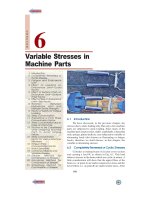
A welded joint is a permanent joint which is obtained
by the fusion of the edges of the two parts to be joined
together, with or without the application of pressure and a
filler material. The heat required for the fusion of the
material may be obtained by burning of gas (in case of gas
welding) or by an electric arc (in case of electric arc
welding). The latter method is extensively used because of
greater speed of welding.
Welding is extensively used in fabrication as an
alternative method for casting or forging and as a
replacement for bolted and riveted joints. It is also used as
a repair medium e.g. to reunite metal at a crack, to build up
a small part that has broken off such as gear tooth or to
repair a worn surface such as a bearing surface.
Welded Joints
341
1. Introduction.
2. Advantages and
Disadvantages of Welded
Joints over Riveted Joints.
3. Welding Processes.
4. Fusion Welding.
5. Thermit Welding.
6. Gas Welding.
7. Electric Arc Welding.
8. Forge Welding.
9. Types of Welded Joints.
10. Lap Joint.
11. Butt Joint.
12. Basic Weld Symbols.
13. Supplementary Weld
Symbols.
14. Elements of a Weld Symbol.
15. Standard Location of
Elements of a Welding
Symbol.
16. Strength of Transverse Fillet
Welded Joints.
17. Strength of Parallel Fillet
Welded Joints.
18. Special Cases of Fillet
Welded Joints.
19. Strength of Butt Joints.
20. Stresses for Welded Joints.
21. Stress Concentration
Factor for Welded Joints.
22. Axially Loaded
Unsymmetrical Welded
Sections.
23. Eccentrically Loaded
Welded Joints.
24. Polar Moment of Inertia
and Section Modulus of
Welds.
10
C
H
A
P
T
E
R
CONTENTS
CONTENTS
CONTENTS
CONTENTS
342
n
A Textbook of Machine Design
342
10.210.2
10.210.2
10.2
AdvAdv
AdvAdv
Adv
antages and Disadvantages and Disadv
antages and Disadvantages and Disadv
antages and Disadv
antages of antages of
antages of antages of
antages of
WW
WW
W
elded Joints oelded Joints o
elded Joints oelded Joints o
elded Joints o
vv
vv
v
er River Riv
er River Riv
er Riv
eted Jointseted Joints
eted Jointseted Joints
eted Joints
Following are the advantages and disadvantages of welded joints over riveted joints.
Advantages
1. The welded structures are usually lighter than riveted structures. This is due to the reason,
that in welding, gussets or other connecting components are not used.
2. The welded joints provide maximum efficiency (may be 100%) which is not possible in
case of riveted joints.
3. Alterations and additions can be easily made in the existing structures.
4. As the welded structure is smooth in appearance, therefore it looks pleasing.
5. In welded connections, the tension members are not weakened as in the case of riveted joints.
6. A welded joint has a great strength. Often a welded joint has the strength of the parent
metal itself.
7. Sometimes, the members are of such a shape (i.e. circular steel pipes) that they afford
difficulty for riveting. But they can be easily welded.
8. The welding provides very rigid joints. This is in line with the modern trend of providing
rigid frames.
9. It is possible to weld any part of a structure at any point. But riveting requires enough
clearance.
10. The process of welding takes less time than the riveting.
Disadvantages
1. Since there is an uneven heating and cooling during fabrication, therefore the members
may get distorted or additional stresses may develop.
2. It requires a highly skilled labour and supervision.
3. Since no provision is kept for expansion and contraction in the frame, therefore there is a
possibility of cracks developing in it.
4. The inspection of welding work is more difficult than riveting work.
10.310.3
10.310.3
10.3
WW
WW
W
elding Prelding Pr
elding Prelding Pr
elding Pr
ocessesocesses
ocessesocesses
ocesses
The welding processes may be broadly classified into the following two groups:
1. Welding processes that use heat
alone e.g. fusion welding.
2. Welding processes that use a
combination of heat and pressure
e.g. forge welding.
These processes are discussed in
detail, in the following pages.
10.410.4
10.410.4
10.4
Fusion Fusion
Fusion Fusion
Fusion
WW
WW
W
eldingelding
eldingelding
elding
In case of fusion welding, the parts to
be jointed are held in position while the
molten metal is supplied to the joint. The
molten metal may come from the parts
themselves (i.e. parent metal) or filler metal
which normally have the composition of the
parent metal. The joint surface become
plastic or even molten because of the heat
Fusion welding at 245°C produces permanent
molecular bonds between sections.
Welded Joints
n
343
from the molten filler metal or other source. Thus, when the molten metal solidifies or fuses, the joint
is formed.
The fusion welding, according to the method of heat generated, may be classified as:
1. Thermit welding, 2. Gas welding, and 3. Electric arc welding.
10.510.5
10.510.5
10.5
TherTher
TherTher
Ther
mit mit
mit mit
mit
WW
WW
W
eldingelding
eldingelding
elding
In thermit welding, a mixture of iron oxide and aluminium called thermit is ignited and the iron
oxide is reduced to molten iron. The molten iron is poured into a mould made around the joint and
fuses with the parts to be welded. A major advantage of the thermit welding is that all parts of weld
section are molten at the same time and the weld cools almost uniformly. This results in a minimum
problem with residual stresses. It is fundamentally a melting and casting process.
The thermit welding is often used in joining iron and steel parts that are too large to be manufac-
tured in one piece, such as rails, truck frames, locomotive frames, other large sections used on steam
and rail roads, for stern frames, rudder frames etc. In steel mills, thermit electric welding is employed
to replace broken gear teeth, to weld new necks on rolls and pinions, and to repair broken shears.
10.610.6
10.610.6
10.6
Gas Gas
Gas Gas
Gas
WW
WW
W
eldingelding
eldingelding
elding
A gas welding is made by applying the flame of an oxy-acetylene or hydrogen gas from a
welding torch upon the surfaces of the prepared joint. The intense heat at the white cone of the flame
heats up the local surfaces to fusion point while the operator manipulates a welding rod to supply the
metal for the weld. A flux is being used to remove the slag. Since the heating rate in gas welding is
slow, therefore it can be used on thinner materials.
10.710.7
10.710.7
10.7
ElectrElectr
ElectrElectr
Electr
ic ic
ic ic
ic
ArAr
ArAr
Ar
c c
c c
c
WW
WW
W
eldingelding
eldingelding
elding
In electric arc welding, the work is prepared in the same manner as for gas welding. In this case
the filler metal is supplied by metal welding electrode. The operator, with his eyes and face protected,
strikes an arc by touching the work of base metal with the electrode. The base metal in the path of the
arc stream is melted, forming a pool of molten metal, which seems to be forced out of the pool by the
blast from the arc, as shown in Fig. 10.1. A small
depression is formed in the base metal and the
molten metal is deposited around the edge of this
depression, which is called the arc crater. The slag
is brushed off after the joint has cooled.
The arc welding does not require the metal
to be preheated and since the temperature of the
arc is quite high, therefore the fusion of the metal
is almost instantaneous. There are two kinds of
arc weldings depending upon the type of electrode.
1. Un-shielded arc welding, and
2. Shielded arc welding.
When a large electrode or filler rod is used for welding, it is then said to be un-shielded arc welding.
In this case, the deposited weld metal while it is hot will absorb oxygen and nitrogen from the atmosphere.
This decreases the strength of weld metal and lower its ductility and resistance to corrosion.
In shielded arc welding, the welding rods coated with solid material are used, as shown in Fig.
10.1. The resulting projection of coating focuses a concentrated arc stream, which protects the globules
of metal from the air and prevents the absorption of large amounts of harmful oxygen and nitrogen.
10.810.8
10.810.8
10.8
ForFor
ForFor
For
ge ge
ge ge
ge
WW
WW
W
eldingelding
eldingelding
elding
In forge welding, the parts to be jointed are first heated to a proper temperature in a furnace or
Fig. 10.1. Shielded electric arc welding.
Electrode
Extruded coating
Gaseous shield
Arc stream
Base metal
Molten pool
Slag
Deposited
metal
344
n
A Textbook of Machine Design
forge and then hammered. This method of welding
is rarely used now-a-days. An electric-resistance
welding is an example of forge welding.
In this case, the parts to be joined are pressed
together and an electric current is passed from one
part to the other until the metal is heated to the
fusion temperature of the joint. The principle of
applying heat and pressure, either sequentially or
simultaneously, is widely used in the processes
known as *spot, seam, projection, upset and flash
welding.
10.910.9
10.910.9
10.9
TT
TT
T
ypes of ypes of
ypes of ypes of
ypes of
WW
WW
W
elded Jointselded Joints
elded Jointselded Joints
elded Joints
Following two types of welded joints are
important from the subject point of view:
1. Lap joint or fillet joint, and 2. Butt joint.
( ) Single transverse.a
( ) Double transverse.b ( ) Parallel fillet.c
Fig. 10.2. Types of lap or fillet joints.
10.10 Lap Joint10.10 Lap Joint
10.10 Lap Joint10.10 Lap Joint
10.10 Lap Joint
The lap joint or the fillet joint is obtained by overlapping the plates and then welding the edges
of the plates. The cross-section of the fillet is approximately triangular. The fillet joints may be
1. Single transverse fillet, 2. Double transverse fillet, and 3. Parallel fillet joints.
The fillet joints are shown in Fig. 10.2. A single transverse fillet joint has the disadvantage that
the edge of the plate which is not welded can buckle or warp out of shape.
10.11 Butt Joint10.11 Butt Joint
10.11 Butt Joint10.11 Butt Joint
10.11 Butt Joint
The butt joint is obtained by placing the plates edge to edge as shown in Fig. 10.3. In butt welds,
the plate edges do not require bevelling if the thickness of plate is less than 5 mm. On the other hand, if
the plate thickness is 5 mm to 12.5 mm, the edges should be bevelled to V or U-groove on both sides.
Fig. 10.3. Types of butt joints.
* For further details, refer author’s popular book ‘A Textbook of Workshop Technology’.
Forge welding.
Welded Joints
n
345
The butt joints may be
1. Square butt joint, 2. Single V-butt joint 3. Single U-butt joint,
4. Double V-butt joint, and 5. Double U-butt joint.
These joints are shown in Fig. 10.3.
The other type of welded joints are corner joint, edge joint and T-joint as shown in Fig. 10.4.
( ) Corner joint.a ( ) Edge joint.b ( ) -joint.cT
Fig. 10.4. Other types of welded joints.
The main considerations involved in the selection of weld type are:
1. The shape of the welded component required,
2. The thickness of the plates to be welded, and
3. The direction of the forces applied.
10.12 Basic 10.12 Basic
10.12 Basic 10.12 Basic
10.12 Basic
WW
WW
W
eld Symbolseld Symbols
eld Symbolseld Symbols
eld Symbols
The basic weld symbols according to IS : 813 – 1961 (Reaffirmed 1991) are shown in the
following table.
TT
TT
T
aa
aa
a
ble 10.1.ble 10.1.
ble 10.1.ble 10.1.
ble 10.1.
Basic w Basic w
Basic w Basic w
Basic w
eld symbolseld symbols
eld symbolseld symbols
eld symbols
.
346
n
A Textbook of Machine Design
Welded Joints
n
347
10.13 Supplementar10.13 Supplementar
10.13 Supplementar10.13 Supplementar
10.13 Supplementar
y y
y y
y
WW
WW
W
eld Symbolseld Symbols
eld Symbolseld Symbols
eld Symbols
In addition to the above symbols, some supplementary symbols, according to IS:813 – 1961
(Reaffirmed 1991), are also used as shown in the following table.
TT
TT
T
aa
aa
a
ble 10.2.ble 10.2.
ble 10.2.ble 10.2.
ble 10.2.
Supplementar Supplementar
Supplementar Supplementar
Supplementar
y wy w
y wy w
y w
eld symbolseld symbols
eld symbolseld symbols
eld symbols
.
10.14 Elements of a 10.14 Elements of a
10.14 Elements of a 10.14 Elements of a
10.14 Elements of a
WW
WW
W
elding Symbolelding Symbol
elding Symbolelding Symbol
elding Symbol
A welding symbol consists of the following eight elements:
1. Reference line, 2. Arrow,
3. Basic weld symbols, 4. Dimensions and other data,
5. Supplementary symbols, 6. Finish symbols,
7. Tail, and 8. Specification, process or other references.
10.15 Standar10.15 Standar
10.15 Standar10.15 Standar
10.15 Standar
d Locad Loca
d Locad Loca
d Loca
tion of Elements of a tion of Elements of a
tion of Elements of a tion of Elements of a
tion of Elements of a
WW
WW
W
elding Symbolelding Symbol
elding Symbolelding Symbol
elding Symbol
According to Indian Standards, IS: 813 – 1961 (Reaffirmed 1991), the elements of a welding
symbol shall have standard locations with respect to each other.
The arrow points to the location of weld, the basic symbols with dimensions are located on one
or both sides of reference line. The specification if any is placed in the tail of arrow. Fig. 10.5 shows
the standard locations of welding symbols represented on drawing.
348
n
A Textbook of Machine Design
Both
.
Arrow
side
Sides
.
Other
side
Field weld symbol
Weld all around symbol
Unwelded length
Length of weld
Finish symbol
Contour symbol
Reference line
Specification
process or
other reference
Tail (omit when
reference is not
used)
Basic weld symbol
or detail reference
Arrow connecting reference
line to arrow side of joint,
to edge prepared member
or both
LP-
S
F
T
Size
Fig. 10.5. Standard location of welding symbols.
Some of the examples of welding symbols represented on drawing are shown in the following table.
TT
TT
T
aa
aa
a
ble 10.3.ble 10.3.
ble 10.3.ble 10.3.
ble 10.3.
Repr Repr
Repr Repr
Repr
esentaesenta
esentaesenta
esenta
tion of wtion of w
tion of wtion of w
tion of w
elding symbolselding symbols
elding symbolselding symbols
elding symbols
.
S. No. Desired weld Representation on drawing
1.
2. Single V-butt weld -machining
finish
3. Double V- butt weld
4.
5.
Fillet-weld each side of
Tee- convex contour
Staggered intermittent fillet welds
Plug weld - 30° Groove-
angle-flush contour
40
40
60
40
40
40
80
100
100
100
5
m
m
(80) 40
(100)
40
(100)
5
5
5
m
m
5
m
m
5
M
10
m
m
10
30º
Welded Joints
n
349
10.16 Str10.16 Str
10.16 Str10.16 Str
10.16 Str
ength of ength of
ength of ength of
ength of
TT
TT
T
ransvransv
ransvransv
ransv
erer
erer
er
se Fillet se Fillet
se Fillet se Fillet
se Fillet
WW
WW
W
elded Jointselded Joints
elded Jointselded Joints
elded Joints
We have already discussed that the fillet or lap joint is obtained by overlapping the plates and
then welding the edges of the plates. The transverse fillet welds are designed for tensile strength. Let
us consider a single and double transverse fillet welds as shown in Fig. 10.6 (a) and (b) respectively.
Fig. 10.6. Transverse fillet welds.
In order to determine the strength of the fillet joint, it is assumed that the section of fillet is a
right angled triangle ABC with hypotenuse AC making equal angles with other two sides AB and BC.
The enlarged view of the fillet is shown in Fig. 10.7. The length of each side is known as leg or size
of the weld and the perpendicular distance of the hypotenuse from the intersection of legs (i.e. BD) is
known as throat thickness. The minimum area of the weld is obtained at the throat BD, which is given
by the product of the throat thickness and length of weld.
Let t = Throat thickness (BD),
s = Leg or size of weld,
= Thickness of plate, and
l = Length of weld,
From Fig. 10.7, we find that the throat thickness,
t = s × sin 45° = 0.707 s
∴ *Minimum area of the weld or throat area,
A = Throat thickness ×
Length of weld
= t × l = 0.707 s × l
If σ
t
is the allowable tensile stress for the weld
metal, then the tensile strength of the joint for single fillet weld,
P = Throat area × Allowable tensile stress = 0.707 s × l × σ
t
and tensile strength of the joint for double fillet weld,
P = 2 × 0.707 s × l × σ
t
= 1.414 s × l × σ
t
Note: Since the weld is weaker than the plate due to slag and blow holes, therefore the weld is given a reinforcement
which may be taken as 10% of the plate thickness.
10.17 Str10.17 Str
10.17 Str10.17 Str
10.17 Str
ength of Pength of P
ength of Pength of P
ength of P
arallel Fillet arallel Fillet
arallel Fillet arallel Fillet
arallel Fillet
WW
WW
W
elded Jointselded Joints
elded Jointselded Joints
elded Joints
The parallel fillet welded joints are designed for shear strength. Consider a double parallel fillet
welded joint as shown in Fig. 10.8 (a). We have already discussed in the previous article, that the
minimum area of weld or the throat area,
A = 0.707 s × l
s
s
t
45º
D
B
A
Reinforcement
C
Fig. 10.7. Enlarged view of a fillet weld.
* The minimum area of the weld is taken because the stress is maximum at the minimum area.
350
n
A Textbook of Machine Design
If τ is the allowable shear stress for the weld metal, then the shear strength of the joint for single
parallel fillet weld,
P = Throat area × Allowable shear stress = 0.707 s × l × τ
and shear strength of the joint for double parallel fillet weld,
P = 2 × 0.707 × s × l × τ = 1.414 s × l × τ
P
P
P
P
( ) Double parallel fillet weld.a
( ) Combination of transverse
and parallel fillet weld.
b
l
1
l
2
Fig. 10.8
Notes: 1. If there is a combination of single transverse and double parallel fillet welds as shown in Fig. 10.8 (b),
then the strength of the joint is given by the sum of strengths of single transverse and double parallel fillet welds.
Mathematically,
P = 0.707s × l
1
× σ
t
+ 1.414 s × l
2
× τ
where l
1
is normally the width of the plate.
2. In order to allow for starting and stopping of the
bead, 12.5 mm should be added to the length of each weld
obtained by the above expression.
3. For reinforced fillet welds, the throat dimension
may be taken as 0.85 t.
Example 10.1. A plate 100 mm wide and
10 mm thick is to be welded to another plate by means
of double parallel fillets. The plates are subjected to
a static load of 80 kN. Find the length of weld if the
permissible shear stress in the weld does not exceed
55 MPa.
Solution. Given: *Width = 100 mm ;
Thickness = 10 mm ; P = 80 kN = 80 × 10
3
N;
τ = 55 MPa = 55 N/mm
2
Let l =Length of weld, and
s = Size of weld = Plate thickness = 10 mm
(Given)
We know that maximum load which the plates can carry for double parallel fillet weld (P),
80 × 10
3
= 1.414 × s × l × τ = 1.414 × 10 × l × 55 = 778 l
∴ l = 80 × 10
3
/ 778 = 103 mm
Adding 12.5 mm for starting and stopping of weld run, we have
l = 103 + 12.5 = 115.5 mm Ans.
Electric arc welding
* Superfluous data.
Welded Joints
n
351
10.1810.18
10.1810.18
10.18
Special Cases of Fillet Special Cases of Fillet
Special Cases of Fillet Special Cases of Fillet
Special Cases of Fillet
WW
WW
W
elded Jointselded Joints
elded Jointselded Joints
elded Joints
The following cases of fillet welded joints are important from the subject point of view.
1. Circular fillet weld subjected to torsion. Consider a circular rod connected to a rigid plate
by a fillet weld as shown in Fig. 10.9.
Let d = Diameter of rod,
r = Radius of rod,
T = Torque acting on the rod,
s = Size (or leg) of weld,
t = Throat thickness,
*J = Polar moment of inertia of the
weld section =
3
4
td
π
We know that shear stress for the material,
τ =
./2
Tr T d
JJ
×
=
=
32
/2 2
/4
Td T
td td
×
=
ππ
τ
=
∵
T
Jr
This shear stress occurs in a horizontal plane along a leg of the fillet weld. The maximum shear
occurs on the throat of weld which is inclined at 45° to the horizontal plane.
∴ Length of throat, t = s sin 45° = 0.707 s
and maximum shear stress,
τ
max
=
22
22.83
0.707
TT
sd sd
=
π× × π
2. Circular fillet weld subjected to bending moment. Consider a circular rod connected to a
rigid plate by a fillet weld as shown in Fig. 10.10.
Let d = Diameter of rod,
M = Bending moment acting on the rod,
s = Size (or leg) of weld,
t = Throat thickness,
**Z = Section modulus of the weld section
=
2
4
td
π
We know that the bending stress,
σ
b
=
22
4
/4
MM M
Z
td td
==
ππ
This bending stress occurs in a horizontal plane along a leg of the
fillet weld. The maximum bending stress occurs on the throat of the
weld which is inclined at 45° to the horizontal plane.
∴ Length of throat, t = s sin 45° = 0.707 s
and maximum bending stress,
σ
b(max)
=
22
45.66
0.707
MM
sd sd
=
π× × π
Fig. 10.9. Circular fillet weld
subjected to torsion.
* See Art, 10.24.
* * See Art, 10.24.
Fig. 10.10. Circular fillet weld
subjected to bending moment.
352
n
A Textbook of Machine Design
3. Long fillet weld subjected to torsion. Consider a
vertical plate attached to a horizontal plate by two identical
fillet welds as shown in Fig. 10.11.
Let T = Torque acting on the vertical plate,
l = Length of weld,
s = Size (or leg) of weld,
t = Throat thickness, and
J = Polar moment of inertia of the weld section
= 2 ×
33
12 6
tl tl
××
=
(∵ of both sides weld)
It may be noted that the effect of the applied torque is
to rotate the vertical plate about the Z-axis through its mid
point. This rotation is resisted by shearing stresses developed between two fillet welds and the horizontal
plate. It is assumed that these horizontal shearing stresses vary from zero at the Z-axis and maximum
at the ends of the plate. This variation of shearing stress is analogous to the variation of normal stress
over the depth (l) of a beam subjected to pure bending.
∴ Shear stress, τ =
32
/2 3
/6
Tl T
tl tl
×
=
××
The maximum shear stress occurs at the throat and is given by
τ
max
=
22
3 4.242
0.707
TT
sl sl
=
××
Example 10.2. A 50 mm diameter solid shaft is welded to a flat
plate by 10 mm fillet weld as shown in Fig. 10.12. Find the maximum
torque that the welded joint can sustain if the maximum shear stress
intensity in the weld material is not to exceed 80 MPa.
Solution. Given : d = 50 mm ; s = 10 mm ; τ
max
= 80 MPa = 80 N/mm
2
Let T = Maximum torque that the welded joint can sustain.
We know that the maximum shear stress (τ
max
),
80 =
22
2.83 2.83 2.83
78550
10 (50)
TTT
sd
==
π× π×
∴ T = 80 × 78 550/2.83
= 2.22 × 10
6
N-mm = 2.22 kN-m Ans.
Example 10.3. A plate 1 m long, 60 mm thick is welded to
another plate at right angles to each other by 15 mm fillet weld, as
shown in Fig. 10.13. Find the maximum torque that the welded
joint can sustain if the permissible shear stress intensity in the
weld material is not to exceed 80 MPa.
Solution. Given: l = 1m = 1000 mm ; Thickness = 60 mm ;
s = 15 mm ; τ
max
= 80 MPa = 80 N/mm
2
Let T = Maximum torque that the
welded joint can sustain.
Fig. 10.11. Long fillet weld subjected
to torsion.
s
Fig. 10.12
Fig. 10.13
Welded Joints
n
353
We know that the maximum shear stress (τ
max
),
80 =
226
4.242 4.242 0.283
15 (1000) 10
TTT
sl
==
×
∴ T =80 × 10
6
/ 0.283 = 283 × 10
6
N-mm = 283 kN-m Ans.
10.1910.19
10.1910.19
10.19
StrStr
StrStr
Str
ength of Butt Jointsength of Butt Joints
ength of Butt Jointsength of Butt Joints
ength of Butt Joints
The butt joints are designed for tension or compression. Consider a single V-butt joint as shown
in Fig. 10.14 (a).
Fig. 10.14. Butt joints.
In case of butt joint, the length of leg or size of weld is equal to the throat thickness which is
equal to thickness of plates.
∴ Tensile strength of the butt joint (single-V or square butt joint),
P = t × l × σ
t
where l = Length of weld. It is generally equal to the width of plate.
and tensile strength for double-V butt joint as shown in Fig. 10.14 (b) is given by
P =(t
1
+ t
2
) l × σ
t
where t
1
= Throat thickness at the top, and
t
2
= Throat thickness at the bottom.
It may be noted that size of the weld should be greater than the thickness of the plate, but it may
be less. The following table shows recommended minimum size of the welds.
TT
TT
T
aa
aa
a
ble 10.4.ble 10.4.
ble 10.4.ble 10.4.
ble 10.4.
Recommended minim Recommended minim
Recommended minim Recommended minim
Recommended minim
um size of wum size of w
um size of wum size of w
um size of w
eldselds
eldselds
elds
.
Thickness of 3 – 5 6 – 8 10 – 16 18 – 24 26 – 55 Over 58
plate (mm)
Minimum size 356101420
of weld (mm)
10.2010.20
10.2010.20
10.20
StrStr
StrStr
Str
esses fesses f
esses fesses f
esses f
or or
or or
or
WW
WW
W
elded Jointselded Joints
elded Jointselded Joints
elded Joints
The stresses in welded joints are difficult to determine because of the variable and unpredictable
parameters like homogenuity of the weld metal, thermal stresses in the welds, changes of physical
properties due to high rate of cooling etc. The stresses are obtained, on the following assumptions:
1. The load is distributed uniformly along the entire length of the weld, and
2. The stress is spread uniformly over its effective section.
The following table shows the stresses for welded joints for joining ferrous metals with mild
steel electrode under steady and fatigue or reversed load.
354
n
A Textbook of Machine Design
TT
TT
T
aa
aa
a
ble 10.5.ble 10.5.
ble 10.5.ble 10.5.
ble 10.5.
Str Str
Str Str
Str
esses fesses f
esses fesses f
esses f
or wor w
or wor w
or w
elded jointselded joints
elded jointselded joints
elded joints
.
Bare electrode Coated electrode
Type of weld
Steady load Fatigue load Steady load Fatigue load
(MPa)(MPa)(MPa)(MPa)
1. Fillet welds (All types) 80 21 98 35
2. Butt welds
Tension 90 35 110 55
Compression 100 35 125 55
Shear 55 21 70 35
Electric arc melts metal
Mask protects welder’s face
Electricity and
gas supply
In TIG (Tungsten Inert Gas) and MIG (Metal Inert Gas) welding processes, the formation of oxide is
prevented by shielding the metal with a blast of gas containing no oxygen.
10.21 Str10.21 Str
10.21 Str10.21 Str
10.21 Str
ess Concentraess Concentra
ess Concentraess Concentra
ess Concentra
tion Ftion F
tion Ftion F
tion F
actor factor f
actor factor f
actor f
or or
or or
or
WW
WW
W
elded Jointselded Joints
elded Jointselded Joints
elded Joints
The reinforcement provided to the weld produces stress concentration at the junction of the
weld and the parent metal. When the parts are subjected to fatigue loading, the stress concentration
factor as given in the following table should be taken into account.
TT
TT
T
aa
aa
a
ble 10.6.ble 10.6.
ble 10.6.ble 10.6.
ble 10.6.
Str Str
Str Str
Str
ess concentraess concentra
ess concentraess concentra
ess concentra
tion ftion f
tion ftion f
tion f
actor factor f
actor factor f
actor f
or wor w
or wor w
or w
elded jointselded joints
elded jointselded joints
elded joints
.
Type of joint Stress concentration factor
1. Reinforced butt welds 1.2
2. Toe of transverse fillet welds 1.5
3. End of parallel fillet weld 2.7
4. T-butt joint with sharp corner 2.0
Note : For static loading and any type of joint, stress concentration factor is 1.0.
Example 10.4. A plate 100 mm wide and 12.5 mm thick is to be welded to another plate by
means of parallel fillet welds. The plates are subjected to a load of 50 kN. Find the length of the weld
so that the maximum stress does not exceed 56 MPa. Consider the joint first under static loading and
then under fatigue loading.
Welded Joints
n
355
Solution. Given: *Width = 100 mm ; Thickness = 12.5 mm ; P = 50 kN = 50 × 10
3
N;
τ = 56 MPa = 56 N/mm
2
Length of weld for static loading
Let l = Length of weld, and
s = Size of weld = Plate thickness
= 12.5 mm (Given)
We know that the maximum load which the
plates can carry for double parallel fillet welds (P),
50 × 10
3
=1.414 s × l × τ
= 1.414 × 12.5 × l × 56 = 990 l
∴ l = 50 × 10
3
/ 990 = 50.5 mm
Adding 12.5 mm for starting and stopping of
weld run, we have
l = 50.5 + 12.5 = 63 mm Ans.
Length of weld for fatigue loading
From Table 10.6, we find that the stress
concentration factor for parallel fillet welding is 2.7.
∴ Permissible shear stress,
τ = 56 / 2.7 = 20.74 N/mm
2
We know that the maximum load which the plates can carry for double parallel fillet welds (P),
50 × 10
3
= 1.414 s × l × τ = 1.414 × 12.5 × l × 20.74 = 367 l
∴ l = 50 × 10
3
/ 367 = 136.2 mm
Adding 12.5 for starting and stopping of weld run, we have
l = 136.2 + 12.5 = 148.7 mm Ans.
Example 10.5. A plate 75 mm wide and 12.5 mm thick is joined with another plate by a single
transverse weld and a double parallel fillet weld as shown in Fig.
10.15. The maximum tensile and shear stresses are 70 MPa and
56 MPa respectively.
Find the length of each parallel fillet weld, if the joint is
subjected to both static and fatigue loading.
Solution. Given : Width = 75 mm ; Thickness = 12.5 mm ;
σ
τ
= 70 MPa = 70 N/mm
2
; τ = 56 MPa = 56 N/mm
2
.
The effective length of weld (l
1
) for the transverse weld may be
obtained by subtracting 12.5 mm from the width of the plate.
∴ l
1
= 75 – 12.5 = 62.5 mm
Length of each parallel fillet for static loading
Let l
2
= Length of each parallel fillet.
We know that the maximum load which the plate can carry is
P = Area × Stress = 75 × 12.5 × 70 = 65 625 N
Load carried by single transverse weld,
P
1
= 0.707 s × l
1
× σ
t
= 0.707 × 12.5 × 62.5 × 70 = 38 664 N
and the load carried by double parallel fillet weld,
P
2
= 1.414 s × l
2
× τ = 1.414 × 12.5 × l
2
× 56 = 990 l
2
N
* Superfluous data.
75 mm
P
P
Fig. 10.15
TIG (Tungsten Inert Gas) welding Machine
356
n
A Textbook of Machine Design
∴ Load carried by the joint (P),
65 625 = P
1
+ P
2
= 38 664 + 990 l
2
or l
2
= 27.2 mm
Adding 12.5 mm for starting and stopping of weld run, we have
l
2
= 27.2 + 12.5 = 39.7 say 40 mm Ans.
Length of each parallel fillet for fatigue loading
From Table 10.6, we find that the stress concentration factor for transverse welds is 1.5 and for
parallel fillet welds is 2.7.
∴ Permissible tensile stress,
σ
t
= 70 / 1.5 = 46.7 N/mm
2
and permissible shear stress,
τ = 56 / 2.7 = 20.74 N/mm
2
Load carried by single transverse weld,
P
1
= 0.707 s × l
1
× σ
t
= 0.707 × 12.5 × 62.5 × 46.7 = 25 795 N
and load carried by double parallel fillet weld,
P
2
= 1.414 s × l
2
× τ = 1.414 × 12.5 l
2
× 20.74 = 366 l
2
N
∴ Load carried by the joint (P),
65 625 = P
1
+ P
2
= 25 795 + 366 l
2
or l
2
= 108.8 mm
Adding 12.5 mm for starting and stopping of weld run, we have
l
2
= 108.8 + 12.5 = 121.3 mm Ans.
Example 10.6. Determine the length of the weld run for a plate of size 120 mm wide and 15 mm
thick to be welded to another plate by means of
1. A single transverse weld; and
2. Double parallel fillet welds when the joint is subjected to
variable loads.
Solution. Given : Width = 120 mm ; Thickness = 15 mm
In Fig. 10.16, AB represents the single transverse weld and AC
and BD represents double parallel fillet welds.
1. Length of the weld run for a single transverse weld
The effective length of the weld run (l
1
) for a single transverse weld may be obtained by subtracting
12.5 mm from the width of the plate.
∴ l
1
= 120 – 12.5 = 107.5 mm Ans.
2. Length of the weld run for a double parallel fillet weld subjected to variable loads
Let l
2
= Length of weld run for each parallel fillet, and
s = Size of weld = Thickness of plate = 15 mm
Assuming the tensile stress as 70 MPa or N/mm
2
and shear stress as 56 MPa or N/mm
2
for static
loading. We know that the maximum load which the plate can carry is
P = Area × Stress = 120 × 15 × 70 = 126 × 10
3
N
From Table 10.6, we find that the stress concentration factor for transverse weld is 1.5 and for
parallel fillet welds is 2.7.
∴ Permissible tensile stress,
σ
t
= 70 / 1.5 = 46.7 N/mm
2
120
A
C
B
D
P
P
Fig. 10.16
Welded Joints
n
357
and permissible shear stress,
τ = 56 / 2.7 = 20.74 N/mm
2
∴ Load carried by single transverse weld,
P
1
= 0.707 s × l
1
× σ
t
= 0.707 × 15 × 107.5 × 46.7 = 53 240 N
and load carried by double parallel fillet weld,
P
2
= 1.414 s × l
2
× τ = 1.414 × 15 × l
2
× 20.74 = 440 l
2
N
∴ Load carried by the joint (P),
126 × 10
3
= P
1
+ P
2
= 53 240 + 440 l
2
or l
2
= 165.4 mm
Adding 12.5 mm for starting and stopping of weld run, we have
l
2
= 165.4 + 12.5 = 177.9 say 178 mm Ans.
Example 10.7. The fillet welds of equal legs are used to fabricate a `T' as shown in Fig. 10.17
(a) and (b), where s is the leg size and l is the length of weld.
Fig. 10.17
Locate the plane of maximum shear stress in each of the following loading patterns:
1. Load parallel to the weld (neglect eccentricity), and
2. Load at right angles to the weld (transverse load).
Find the ratio of these limiting loads.
Solution. Given : Leg size = s ; Length of weld = l
1. Plane of maximum shear stress when load acts parallel to the weld (neglecting eccentricity)
Let θ = Angle of plane of maximum shear stress, and
t = Throat thickness BD.
From the geometry of Fig. 10.18, we find that
BC = BE + EC
= BE + DE (
∵
EC = DE)
or s = BD cos θ + BD sin θ
= t cos θ + t sin θ
= t (cos θ + sin θ)
∴ t =
cos sin
s
θ+ θ
We know that the minimum area of the weld or throat area,
A =2t × l =
2
(cos sin )
sl
×
θ+ θ
(
∵
of double fillet weld)
q
q
45º
45º
s
s
A
B
E
C
D
t
Fig. 10.18
358
n
A Textbook of Machine Design
and shear stress, τ =
(cos sin )
2
θ+ θ
=
×
PP
Asl
(i)
For maximum shear stress, differentiate the above expression with respect to θ and equate to zero.
∴
2
dP
dsl
τ
=
θ×
( – sin θ + cos θ) = 0
or sin θ = cos θ or θ = 45°
Substituting the value of θ = 45° in equation (i), we have maximum shear stress,
τ
max
=
(cos 45 sin 45 ) 1.414
22
PP
sl sl
°+ °
=
××
or P =
2
1.414
1.414
max
max
sl
sl
××τ
=××τ
Ans.
2. Plane of maximum shear stress when load acts at right angles to the weld
When the load acts at right angles to the weld (transverse load), then the shear force and the
normal force will act on each weld. Assuming that the two welds share the load equally, therefore
summing up the vertical components, we have from Fig. 10.19,
P =
sin cos sin cos
2222
sn sn
PP PP
θ+ θ+ θ+ θ
= P
s
sin θ + P
n
cos θ (i)
q
q
(90 )-q
(90 )-q
P
n
2
P
n
2
P
s
2
P
s
2
P
n
2
P
n
2
P
n
2
P
n
2
P
n
2
P
n
2
P
s
2
P
s
2
P
s
2
P
s
2
P
s
2
P
s
2
cos q
cos q
cos q
cos q
sin q
sin q
sin q
sin q
A
P
BEC
D
s
s
Fig. 10.19
Assuming that the resultant of
and
22
sn
PP
is vertical, then the horizontal components are equal
and opposite. We know that
Horizontal component of
cos
22
ss
PP
=θ
and horizontal component of
sin
22
nn
PP
=θ
∴
cos
cos sin or
22 sin
sn s
n
PP P
P
θ
θ= θ =
θ
Substituting the value of P
n
in equation (i), we have
P =
cos cos
sin
sin
s
s
P
P
θ× θ
θ+
θ
Multiplying throughout by sin θ, we have
P sin θ = P
s
sin
2
θ + P
s
cos
2
θ
= P
s
(sin
2
θ + cos
2
θ) = P
s
(ii)
Welded Joints
n
359
From the geometry of Fig. 10.19, we have
BC = BE + EC = BE + DE (
∵
EC = DE)
or s = t cos θ + t sin θ = t (cos θ + sin θ)
∴ Throat thickness, t =
cos sin
s
θ+ θ
and minimum area of the weld or throat area,
A = 2t × l (∵ of double fillet weld)
=
2
2
cos sin cos sin
ssl
l
×
××=
θ+ θ θ+ θ
∴ Shear stress,
τ
=
sin (cos sin )
2
s
P
P
Asl
θθ+θ
=
×
[From equation (ii)] (iii)
For maximum shear stress, differentiate the above expression with respect to θ and equate to zero.
∴
[]
sin ( sin cos ) (cos sin ) cos 0
2
dP
dsl
τ
= θ−θ+ θ+ θ+θ θ=
θ
(.)
=+
θθθ
∵
duv dv du
uv
ddd
or – sin
2
θ + sin θ cos θ + cos
2
θ + sin θ cos θ = 0
cos
2
θ – sin
2
θ + 2sin θ cos θ = 0
Since cos
2
θ – sin
2
θ = cos 2θ and 2 sin θ cos θ = sin 2θ, therefore,
cos 2θ + sin 2θ =0
or sin 2θ = – cos 2θ
sin 2
1
cos 2
θ
=−
θ
or tan 2θ = – 1
∴ 2θ = 135° or θ = 67.5° Ans.
Substituting the value of θ = 67.5° in equation (iii), we have maximum shear stress,
τ
max
=
sin 67.5 (cos 67.5 sin 67.5 )
2
P
sl
°°+°
×
=
0.9239 (0.3827 0.9229) 1.21
22
PP
sl sl
×+
=
××
and P =
2
1.65
1.21
max
max
sl
sl
××τ
=××τ
Ans.
Ratio of the limiting loads
We know that the ratio of the limiting (or maximum) loads
=
1.414
0.857
1.65
max
max
sl
sl
××τ
=
××τ
Ans.
10.22 10.22
10.22 10.22
10.22
Axially Loaded UnsymmetrAxially Loaded Unsymmetr
Axially Loaded UnsymmetrAxially Loaded Unsymmetr
Axially Loaded Unsymmetr
ical ical
ical ical
ical
WW
WW
W
eldedelded
eldedelded
elded
SectionsSections
SectionsSections
Sections
Sometimes unsymmetrical sections such as angles,
channels, T-sections etc., welded on the flange edges are loaded
axially as shown in Fig. 10.20. In such cases, the lengths of weld
should be proportioned in such a way that the sum of resisting
moments of the welds about the gravity axis is zero. Consider an
angle section as shown in Fig. 10.20.
Plasma arc welding
360
n
A Textbook of Machine Design
Let l
a
= Length of weld at the top,
l
b
= Length of weld at the bottom,
l = Total length of weld = l
a
+ l
b
P = Axial load,
a = Distance of top weld from gravity axis,
b = Distance of bottom weld from gravity axis, and
f = Resistance offered by the weld per unit length.
Fig. 10.20. Axially loaded unsymmetrical welded section.
∴ Moment of the top weld about gravity axis
= l
a
× f × a
and moment of the bottom weld about gravity axis
= l
b
× f × b
Since the sum of the moments of the weld about the gravity axis must be zero, therefore,
l
a
× f × a – l
b
× f × b =0
or l
a
× a = l
b
× b (i)
We know that l = l
a
+ l
b
(ii)
∴ From equations (i) and (ii), we have
l
a
=
,and
b
lb la
l
ab ab
××
=
++
Example 10.8. A 200 × 150 × 10 mm angle is to be welded to a steel plate by fillet welds as
shown in Fig. 10.21. If the angle is subjected to a static load of 200 kN, find the length of weld at the
top and bottom. The allowable shear stress for static loading may be taken as 75 MPa.
Fig. 10.21
Solution. Given : a + b = 200 mm ; P = 200 kN = 200 × 10
3
N; τ = 75 MPa = 75 N/mm
2
Let l
a
= Length of weld at the top,
l
b
= Length of weld at the bottom, and
l = Total length of the weld = l
a
+ l
b
Welded Joints
n
361
Since the thickness of the angle is 10 mm, therefore size of weld,
s = 10 mm
We know that for a single parallel fillet weld, the maximum load (P),
200 × 10
3
= 0.707 s × l × τ = 0.707 × 10 × l × 75 = 530.25 l
∴ l = 200 × 10
3
/ 530.25 = 377 mm
or l
a
+ l
b
= 377 mm
Now let us find out the position of the centroidal axis.
Let b = Distance of centroidal axis from the bottom of the angle.
∴ b =
(200 10) 10 95 150 10 5
60.88 mm
190 10 150 10
−×+××
=
×+ ×
and a = 200 – 55.3 = 144.7 mm
We know that l
a
=
377 60.88
114.76 mm
200
lb
ab
××
==
+
Ans.
and l
b
= l – l
a
= 377 – 114.76 = 262.24 mm Ans.
10.23 Eccentr10.23 Eccentr
10.23 Eccentr10.23 Eccentr
10.23 Eccentr
ically Loaded ically Loaded
ically Loaded ically Loaded
ically Loaded
WW
WW
W
elded Jointselded Joints
elded Jointselded Joints
elded Joints
An eccentric load may be imposed on welded joints in many ways. The stresses induced on the
joint may be of different nature or of the same nature. The induced stresses are combined depending
upon the nature of stresses. When the shear and bending stresses are simultaneously present in a joint
(see case 1), then maximum stresses are as follows:
Maximum normal stress,
σ
t(max)
=
22
1
() 4
22
b
b
σ
+σ+τ
and maximum shear stress,
τ
max
=
22
1
() 4
2
b
σ+τ
where σ
b
= Bending stress, and
τ = Shear stress.
When the stresses are of the same nature, these may be combined
vectorially (see case 2).
We shall now discuss the two cases of eccentric loading as follows:
Case 1
Consider a T-joint fixed at one end and subjected to an eccentric load P at a distance e as shown
in Fig. 10.22.
Let s = Size of weld,
l = Length of weld, and
t = Throat thickness.
The joint will be subjected to the following two types of stresses:
1. Direct shear stress due to the shear force P acting at the welds, and
2. Bending stress due to the bending moment P × e.
We know that area at the throat,
A = Throat thickness × Length of weld
= t × l × 2 = 2 t × l (For double fillet weld)
= 2 × 0.707 s × l = 1.414 s × l (
∵
t = s cos 45° = 0.707 s)
Fig. 10.22. Eccentrically
loaded welded joint.
362
n
A Textbook of Machine Design
∴ Shear stress in the weld (assuming uniformly distributed),
τ =
1.414
PP
Asl
=
×
Section modulus of the weld metal through the throat,
Z =
2
2
6
tl
×
×
(For both sides weld)
=
22
0.707
2
6 4.242
sl sl
××
×=
Bending moment, M = P × e
∴ Bending stress, σ
b
=
22
4.242 4.242
MPe Pe
Z
sl sl
×× ×
==
××
We know that the maximum normal stress,
σ
t(max)
=
22
11
() 4
22
bb
σ+ σ + τ
and maximum shear stress,
τ
max
=
22
1
() 4
2
b
σ+τ
Case 2
When a welded joint is loaded eccentrically as shown in Fig. 10.23,
the following two types of the stresses are induced:
1. Direct or primary shear stress, and
2. Shear stress due to turning moment.
Fig. 10.23. Eccentrically loaded welded joint.
Let P = Eccentric load,
e = Eccentricity i.e. perpendicular distance between the line of action of
load and centre of gravity (G) of the throat section
or fillets,
l = Length of single weld,
s = Size or leg of weld, and
t = Throat thickness.
Let two loads P
1
and P
2
(each equal to P) are introduced at the centre of gravity ‘G' of the weld
system. The effect of load P
1
= P is to produce direct shear stress which is assumed to be uniform over
the entire weld length. The effect of load P
2
= P is to produce a turning moment of magnitude P × e
which tends of rotate the joint about the centre of gravity ‘G' of the weld system. Due to the turning
moment, secondary shear stress is induced.
Soldering is done
by melting a metal
which melts at a
lower temperature
than the metal that
is soldered.
Welded Joints
n
363
We know that the direct or primary shear stress,
τ
1
=
Load
Throat area 2
PP
Atl
==
×
=
2 0.707 1.414
PP
sl sl
=
×× ×
(∵ Throat area for single fillet weld = t × l = 0.707 s × l)
Since the shear stress produced due to the turning moment (T = P × e) at any section is proportional
to its radial distance from G, therefore stress due to P × e at the point A is proportional to AG (r
2
) and
is in a direction at right angles to AG. In other words,
2
2
Constant
rr
ττ
==
or τ =
2
2
r
r
τ
×
(i)
where τ
2
is the shear stress at the maximum distance (r
2
) and τ is the shear stress at any distance r.
Consider a small section of the weld having area dA at a distance r from G.
∴ Shear force on this small section
= τ × dA
and turning moment of this shear force about G,
dT =
2
2
2
dA r dA r
r
τ
τ× × = × ×
[ From equation (i)]
∴ Total turning moment over the whole weld area,
T =
22
22
22
Pe dAr dAr
rr
ττ
×= × × = ×
∫∫
=
2
2
J
r
τ
×
()
2
=×
∫
∵ JdAr
where J = Polar moment of inertia of the throat area about G.
∴ Shear stress due to the turning moment i.e. secondary shear stress,
τ
2
=
22
×××
=
Tr Per
JJ
In order to find the resultant stress, the primary and secondary shear stresses are combined
vectorially.
∴ Resultant shear stress at A,
τ
A
=
22
12 12
() () 2 cos
τ+τ+τ×τ× θ
where θ = Angle between τ
1
and τ
2
, and
cos θ = r
1
/ r
2
Note:The polar moment of inertia of the throat area (A) about the centre of gravity (G) is obtained by the parallel
axis theorem, i.e.
J =2 [I
xx
+ A × x
2
] (∵ of double fillet weld)
=2
2
22
2
2
12 12
×
+× = +
Al l
Ax A x
where A = Throat area = t × l = 0.707 s × l,
l = Length of weld, and
x = Perpendicular distance between the two parallel axes.
364
n
A Textbook of Machine Design
10.2410.24
10.2410.24
10.24
PP
PP
P
olar Moment of Inerolar Moment of Iner
olar Moment of Inerolar Moment of Iner
olar Moment of Iner
tia and Section Modulus of tia and Section Modulus of
tia and Section Modulus of tia and Section Modulus of
tia and Section Modulus of
WW
WW
W
eldselds
eldselds
elds
The following table shows the values of polar moment of inertia of the throat area about the
centre of gravity ‘G’ and section modulus for some important types of welds which may be used for
eccentric loading.
TT
TT
T
aa
aa
a
ble 10.7.ble 10.7.
ble 10.7.ble 10.7.
ble 10.7.
P P
P P
P
olar moment of inerolar moment of iner
olar moment of inerolar moment of iner
olar moment of iner
tia and section modulus of wtia and section modulus of w
tia and section modulus of wtia and section modulus of w
tia and section modulus of w
eldselds
eldselds
elds
.
S.No Type of weld Polar moment of inertia (J) Section modulus (Z)
1.
3
.
12
tl
—
2.
3
.
12
tb
2
.
6
tb
3.
22
.(3 )
6
+tl b l
t.b.l
4.
22
.( 3 )
6
+tb b l
2
.
3
tb
5.
3
()
6
+tb l
2
.
3
+
b
tbl
Welded Joints
n
365
S.No Type of weld Polar moment of inertia (J) Section modulus (Z)
6.
b
x
y
l
G
422
()6
12 ( )
+−
+
bl bl
t
lb
2
2
4.
(Top)
6
(4 )
6(2 )
(Bottom)
+
+
+
lb b
t
blbb
t
lb
22
,
2( ) 2( )
==
++
lb
xy
lb lb
7.
b
x
l
G
32 2
(2) ( )
12 2
++
−
+
bl lbl
t
bl
2
.
6
+
b
tlb
2
2
=
+
l
x
lb
8.
d
s
t
3
4
πtd
2
4
πtd
Note: In the above expressions, t is the throat thickness and s is the size of weld. It has already been discussed
that t = 0.707 s.
Example 10.9. A welded joint as shown in Fig. 10.24, is subjected to an eccentric load of 2 kN.
Find the size of weld, if the maximum shear stress in the weld
is 25 MPa.
Solution. Given: P = 2kN = 2000 N ; e = 120 mm ;
l = 40 mm ; τ
max
= 25 MPa = 25 N/mm
2
Let s = Size of weld in mm, and
t = Throat thickness.
The joint, as shown in Fig. 10.24, will be subjected to
direct shear stress due to the shear force, P = 2000 N and
bending stress due to the bending moment of P × e.
We know that area at the throat,
A =2t × l = 2 × 0.707 s × l
= 1.414 s × l
= 1.414 s × 40 = 56.56 × s mm
2
t
s
40 mm
120 mm
2kN
Fig. 10.24