Text Book of Machine Design P30
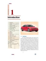
Bạn đang xem bản rút gọn của tài liệu. Xem và tải ngay bản đầy đủ của tài liệu tại đây (361.09 KB, 21 trang )
1080
n
A Textbook of Machine Design
Bevel Gears
1080
1. Introduction.
2. Classification of Bevel
Gears.
3. Terms used in Bevel Gears.
4. Determination of Pitch
Angle for Bevel Gears.
5. Proportions for Bevel Gears.
6. Formative or Equivalent
Number of Teeth for Bevel
Gears—Tredgold's
Approximation.
7. Strength of Bevel Gears.
8. Forces Acting on a Bevel
Gear.
9. Design of a Shaft for Bevel
Gears.
30
C
H
A
P
T
E
R
30.130.1
30.130.1
30.1
IntrIntr
IntrIntr
Intr
oductionoduction
oductionoduction
oduction
The bevel gears are used for transmitting power at a
constant velocity ratio between two shafts whose axes
intersect at a certain angle. The pitch surfaces for the bevel
gear are frustums of cones. The two pairs of cones in contact
is shown in Fig. 30.1. The elements of the cones, as shown
in Fig. 30.1 (a), intersect at the point of intersection of the
axis of rotation. Since the radii of both the gears are
proportional to their distances from the apex, therefore the
cones may roll together without sliding. In Fig. 30.1 (b),
the elements of both cones do not intersect at the point of
shaft intersection. Consequently, there may be pure rolling
at only one point of contact and there must be tangential
sliding at all other points of contact. Therefore, these cones,
cannot be used as pitch surfaces because it is impossible to
have positive driving and sliding in the same direction at
the same time. We, thus, conclude that the elements of bevel
CONTENTS
CONTENTS
CONTENTS
CONTENTS
Bevel Gears
n
1081
gear pitch cones and shaft axes must intersect at the same point.
Fig. 30.1. Pitch surface for bevel gears.
30.230.2
30.230.2
30.2
Classification of Bevel GearsClassification of Bevel Gears
Classification of Bevel GearsClassification of Bevel Gears
Classification of Bevel Gears
The bevel gears may be classified into the following types, depending upon the angles between
the shafts and the pitch surfaces.
1. Mitre gears. When equal bevel gears (having equal teeth and equal pitch angles) connect two
shafts whose axes intersect at right angle, as shown in Fig. 30.2 (a), then they are known as mitre gears.
2. Angular bevel gears. When the bevel gears connect two shafts whose axes intersect at an
angle other than a right angle, then they are known as angular bevel gears.
The bevel gear is used to change the axis of rotational motion. By using gears of differing
numbers of teeth, the speed of rotation can also be changed.
1082
n
A Textbook of Machine Design
3. Crown bevel gears. When the bevel gears connect two shafts whose axes intersect at an angle
greater than a right angle and one of the bevel gears has a pitch angle of 90º, then it is known as a
crown gear. The crown gear corresponds to a rack in spur gearing, as shown in Fig. 30.2 (b).
Fig. 30.2. Classification of bevel gears.
4. Internal bevel gears. When the teeth on the bevel gear are cut on the inside of the pitch cone,
then they are known as internal bevel gears.
Note : The bevel gears may have straight or spiral teeth. It may be assumed, unless otherwise stated, that the
bevel gear has straight teeth and the axes of the shafts intersect at right angle.
30.330.3
30.330.3
30.3
TT
TT
T
erer
erer
er
ms used in Bems used in Be
ms used in Bems used in Be
ms used in Be
vv
vv
v
el Gearel Gear
el Gearel Gear
el Gear
ss
ss
s
Fig. 30.3. Terms used in bevel gears.
A sectional view of two bevel gears in mesh is shown in Fig. 30.3. The following terms in
connection with bevel gears are important from the subject point of view :
Bevel Gears
n
1083
1. Pitch cone. It is a cone containing the pitch elements of the teeth.
2. Cone centre. It is the apex of the pitch cone. It may be defined as that point where the axes of
two mating gears intersect each other.
3. Pitch angle. It is the angle made by the pitch line with the axis of the shaft. It is denoted by ‘θ
P
’.
4. Cone distance. It is the length of the pitch cone element. It is also called as a pitch cone
radius. It is denoted by ‘OP’. Mathematically, cone distance or pitch cone radius,
OP =
GP
PP1P2
/2
/2Pitch radius
sin
èsinsin
D
D
==
θθ
5. Addendum angle. It is the angle subtended by the addendum of the tooth at the cone centre.
It is denoted by ‘α’ Mathematically, addendum angle,
α = tan
–1
a
OP
where a = Addendum, and OP = Cone distance.
6. Dedendum angle. It is the angle subtended by the dedendum of the tooth at the cone centre.
It is denoted by ‘β’. Mathematically, dedendum angle,
β = tan
–1
d
OP
where d = Dedendum, and OP = Cone distance.
7. Face angle. It is the angle subtended by the face of the tooth at the cone centre. It is denoted
by ‘φ’. The face angle is equal to the pitch angle plus addendum angle.
8. Root angle. It is the angle subtended by the root of the tooth at the cone centre. It is denoted
by ‘θ
R
’. It is equal to the pitch angle minus dedendum angle.
9. Back (or normal) cone. It is an imaginary cone, perpendicular to the pitch cone at the end of
the tooth.
10. Back cone distance. It is the length of the back cone. It is denoted by ‘R
B
’. It is also called
back cone radius.
11. Backing. It is the distance of the pitch point (P) from the back of the boss, parallel to the
pitch point of the gear. It is denoted by ‘B’.
12. Crown height. It is the distance of the crown point (C) from the cone centre (O), parallel to
the axis of the gear. It is denoted by ‘H
C
’.
13. Mounting height. It is the distance of the back of the boss from the cone centre. It is
denoted by ‘H
M
’.
14. Pitch diameter. It is the diameter of the largest pitch circle.
15. Outside or addendum cone diameter. It is the maximum diameter of the teeth of the gear.
It is equal to the diameter of the blank from which the gear can be cut. Mathematically, outside
diameter,
D
O
= D
P
+ 2α cos θ
P
where D
P
= Pitch circle diameter,
α = Addendum, and
θ
P
= Pitch angle.
16. Inside or dedendum cone diameter. The inside or the dedendum cone diameter is given by
D
d
= D
P
– 2d cos θ
P
where D
d
= Inside diameter, and
d = Dedendum.
1084
n
A Textbook of Machine Design
30.430.4
30.430.4
30.4
DeterDeter
DeterDeter
Deter
minamina
minamina
mina
tion of Pitch tion of Pitch
tion of Pitch tion of Pitch
tion of Pitch
Angle fAngle f
Angle fAngle f
Angle f
oror
oror
or
Bevel GearsBevel Gears
Bevel GearsBevel Gears
Bevel Gears
Consider a pair of bevel gears in mesh, as
shown in Fig. 30.3.
Let θ
P1
= Pitch angle for the pinion,
θ
P2
= Pitch angle for the gear,
θ
S
= Angle between the two shaft axes,
D
P
= Pitch diameter of the pinion,
D
G
= Pitch diameter of the gear, and
V.R. = Velocity ratio =
GG
P
PP G
DTN
DTN
==
From Fig. 30.3, we find that
θ
S
= θ
P1
+ θ
P2
or θ
P2
= θ
S
– θ
P1
∴ sin θ
P2
=sin (θ
S
– θ
P1
) = sin θ
S
. cos θ
P1
– cos θ
S
. sin θ
P1
...
(i)
We know that cone distance,
OP =
G
P
P1 P2
/2/2
sin sin
DD
=
θθ
or
GP2
P1 P
sin
sin
D
D
θ
=
θ
= V.R.
∴ sin θ
P2
= V.R. × sin θ
P1
...
(ii)
From equations (i) and (ii), we have
V.R. × sin θ
P1
= sin θ
S
. cos θ
P1
– cos θ
S
. sin θ
P1
Dividing throughout by cos θ
P1
we get
V.R. tan θ
P1
= sin θ
S
– cos θ
S
. tan θ
P1
or tan θ
P1
=
S
S
sin
V.R cos
θ
+θ
∴θ
P1
= tan
–1
S
S
sin
V.R cos
θ
+θ
...
(iii)
Similarly, we can find that
tan θ
P2
=
S
S
sin
1
cos
V.R
θ
+θ
∴θ
P2
= tan
–1
S
S
sin
1
cos
V.R
θ
+θ
...
(iv)
Note :
When the angle between the shaft axes is 90º i.e. θ
S
= 90º, then equations (iii) and (iv) may be written as
θ
P1
= tan
–1
1
V.R
= tan
–1
P
G
D
D
= tan
–1
P
G
T
T
= tan
–1
G
P
N
N
and θ
P2
= tan
–1
(V.R.) = tan
–1
G
P
D
D
= tan
–1
G
P
T
T
= tan
–1
P
G
T
N
30.530.5
30.530.5
30.5
PrPr
PrPr
Pr
oporopor
oporopor
opor
tions ftions f
tions ftions f
tions f
or Beor Be
or Beor Be
or Be
vv
vv
v
el Gearel Gear
el Gearel Gear
el Gear
The proportions for the bevel gears may be taken as follows :
1. Addendum, a = 1 m
Mitre gears
Bevel Gears
n
1085
2. Dedendum, d = 1.2 m
3. Clearance = 0.2 m
4. Working depth = 2 m
5. Thickness of tooth = 1.5708 m
where m is the module.
Note : Since the bevel gears are not interchangeable, therefore these are designed in pairs.
30.630.6
30.630.6
30.6
For For
For For
For
mama
mama
ma
tivtiv
tivtiv
tiv
e or Equive or Equiv
e or Equive or Equiv
e or Equiv
alent Number of alent Number of
alent Number of alent Number of
alent Number of
TT
TT
T
eeth feeth f
eeth feeth f
eeth f
or Beor Be
or Beor Be
or Be
vv
vv
v
el Gearel Gear
el Gearel Gear
el Gear
s – s –
s – s –
s –
TT
TT
T
rr
rr
r
edgold’edgold’
edgold’edgold’
edgold’
ss
ss
s
ApprAppr
ApprAppr
Appr
oo
oo
o
ximaxima
ximaxima
xima
tiontion
tiontion
tion
We have already discussed that the involute teeth for a spur gear may be generated by the edge
of a plane as it rolls on a base cylinder. A similar analysis for a bevel gear will show that a true section
of the resulting involute lies on the surface of a sphere. But it is not possible to represent on a plane
surface the exact profile of a bevel gear tooth lying on the surface of a sphere. Therefore, it is
important to approximate the bevel gear tooth profiles as accurately as possible. The approximation
(known as Tredgold’s approximation) is based upon the fact that a cone tangent to the sphere at the
pitch point will closely approximate the surface of the sphere for a short distance either side of the
pitch point, as shown in Fig. 30.4 (a). The cone (known as back cone) may be developed as a plane
surface and spur gear teeth corresponding to the pitch and pressure angle of the bevel gear and the
radius of the developed cone can be drawn. This procedure is shown in Fig. 30.4 (b).
Fig. 30.4
Let θ
P
= Pitch angle or half of the cone angle,
R = Pitch circle radius of the bevel pinion or gear, and
R
B
= Back cone distance or equivalent pitch circle radius of spur pinion
or gear.
Now from Fig. 30.4 (b), we find that
R
B
= R sec θ
P
We know that the equivalent (or formative) number of teeth,
T
E
=
B
2
R
m
...
Pitch circle diameter
Number of teeth =
Module
∵
=
P
P
2sec
sec
R
T
m
θ
=θ
where T = Actual number of teeth on the gear.
1086
n
A Textbook of Machine Design
Notes : 1. The action of bevel gears will be same as that of equivalent spur gears.
2. Since the equivalent number of teeth is always greater than the actual number of teeth, therefore a
given pair of bevel gears will have a larger contact ratio. Thus, they will run more smoothly than a pair of spur
gears with the same number of teeth.
30.730.7
30.730.7
30.7
StrStr
StrStr
Str
ength of Beength of Be
ength of Beength of Be
ength of Be
vv
vv
v
el Gearel Gear
el Gearel Gear
el Gear
ss
ss
s
The strength of a bevel gear tooth is obtained in a similar way as discussed in the previous
articles. The modified form of the Lewis equation for the tangential tooth load is given as follows:
W
T
=(σ
o
× C
v
) b.π m.y'
Lb
L
−
where σ
o
= Allowable static stress,
C
v
= Velocity factor,
=
3
3
v
+
, for teeth cut by form cutters,
=
6
6
v
+
, for teeth generated with precision machines,
v = Peripheral speed in m / s,
b = Face width,
m = Module,
y' = Tooth form factor (or Lewis factor) for the equivalent number of
teeth,
L = Slant height of pitch cone (or cone distance),
=
22
G
P
22
DD
+
Hypoid bevel gears in a car differential
Input
Pinion
Drive
shaft
Ring gear
Bevel Gears
n
1087
D
G
= Pitch diameter of the gear, and
D
P
= Pitch diameter of the pinion.
Notes : 1. The factor
Lb
L
−
may be called as bevel factor.
2. For satisfactory operation of the bevel gears, the face width should be from 6.3 m to 9.5 m, where m is
the module. Also the ratio L / b should not exceed 3. For this, the number of teeth in the pinion must not less than
2
48
1(..)
VR+
, where V.R. is the required velocity ratio.
3. The dynamic load for bevel gears may be obtained in the similar manner as discussed for spur gears.
4. The static tooth load or endurance strength of the tooth for bevel gears is given by
W
S
= σ
e
.b.π m.y'
–
Lb
L
The value of flexural endurance limit (σ
e
) may be taken from Table 28.8, in spur gears.
5. The maximum or limiting load for wear for bevel gears is given by
W
w
=
P
P1
.. .
cos
DbQK
θ
where D
P
, b, Q and K have usual meanings as discussed in spur gears except that Q is based on formative or
equivalent number of teeth, such that
Q =
EG
EG EP
2
T
TT
+
30.830.8
30.830.8
30.8
ForFor
ForFor
For
ces ces
ces ces
ces
Acting on a BeActing on a Be
Acting on a BeActing on a Be
Acting on a Be
vv
vv
v
el Gearel Gear
el Gearel Gear
el Gear
Consider a bevel gear and pinion in mesh as shown in Fig. 30.5. The normal force (W
N
) on the
tooth is perpendicular to the tooth profile and thus makes an angle equal to the pressure angle (φ) to
the pitch circle. Thus normal force can be resolved into two components, one is the tangential component
(W
T
) and the other is the radial component (W
R
). The tangential component (i.e. the tangential tooth
load) produces the bearing reactions while the radial component produces end thrust in the shafts.
The magnitude of the tangential and radial components is as follows :
W
T
= W
N
cos φ, and W
R
= W
N
sin φ = W
T
tan φ ...
(i)