Text Book of Machine Design P31
Bạn đang xem bản rút gọn của tài liệu. Xem và tải ngay bản đầy đủ của tài liệu tại đây (569.15 KB, 24 trang )
Worm Gears
n
1101
Worm Gears
1101
31
C
H
A
P
T
E
R
1. Introduction
2. Types of Worms
3. Types of Worm Gears.
4. Terms used in Worm
Gearing.
5. Proportions for Worms .
6. Proportions for Worm Gears.
7. Efficiency of Worm Gearing.
8. Strength of Worm Gear
Teeth .
9. Wear Tooth Load for Worm
Gear.
10. Thermal Rating of Worm
Gearing.
11. Forces Acting on Worm
Gears.
12. Design of Worm Gearing.
31.131.1
31.131.1
31.1
IntrIntr
IntrIntr
Intr
oductionoduction
oductionoduction
oduction
The worm gears are widely used for transmitting
power at high velocity ratios between non-intersecting
shafts that are generally, but not necessarily, at right angles.
It can give velocity ratios as high as 300 : 1 or more in a
single step in a minimum of space, but it has a lower
efficiency. The worm gearing is mostly used as a speed
reducer, which consists of worm and a worm wheel or
gear. The worm (which is the driving member) is usually
of a cylindrical form having threads of the same shape as
that of an involute rack. The threads of the worm may be
left handed or right handed and single or multiple threads.
The worm wheel or gear (which is the driven member) is
similar to a helical gear with a face curved to conform to
the shape of the worm. The worm is generally made of
steel while the worm gear is made of bronze or cast iron
for light service.
CONTENTS
CONTENTS
CONTENTS
CONTENTS
1102
n
A Textbook of Machine Design
The worm gearing is classified as non-interchangeable, because a worm wheel cut with a hob of
one diameter will not operate satisfactorily with a worm of different diameter, even if the thread pitch
is same.
31.231.2
31.231.2
31.2
TT
TT
T
ypes of ypes of
ypes of ypes of
ypes of
WW
WW
W
oror
oror
or
msms
msms
ms
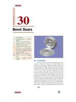
The following are the two types of worms :
1. Cylindrical or straight worm, and
2. Cone or double enveloping worm.
The cylindrical or straight worm, as shown in Fig. 31.1 (a), is most commonly used. The shape
of the thread is involute helicoid of pressure angle 14 ½° for single and double threaded worms and
20° for triple and quadruple threaded worms. The worm threads are cut by a straight sided milling
cutter having its diameter not less than the outside diameter of worm or greater than 1.25 times the
outside diameter of worm.
The cone or double enveloping worm, as shown in Fig. 31.1 (b), is used to some extent, but it
requires extremely accurate alignment.
Fig. 31.1. Types of worms.
31.331.3
31.331.3
31.3
TT
TT
T
ypes of ypes of
ypes of ypes of
ypes of
WW
WW
W
oror
oror
or
m Gearm Gear
m Gearm Gear
m Gear
ss
ss
s
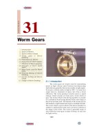
The following three types of worm gears are important from the subject point of view :
1. Straight face worm gear, as shown in Fig. 31.2 (a),
2. Hobbed straight face worm gear, as shown in Fig. 31.2 (b), and
3. Concave face worm gear, as shown in Fig. 31.2 (c).
Fig. 31.2. Types of worms gears.
The straight face worm gear is like a helical gear in which the straight teeth are cut with a form
cutter. Since it has only point contact with the worm thread, therefore it is used for light service.
The hobbed straight face worm gear is also used for light service but its teeth are cut with a
hob, after which the outer surface is turned.
Worm Gears
n
1103
The concave face worm gear is the accepted standard form and is used for all heavy service and
general industrial uses. The teeth of this gear are cut with a hob of the same pitch diameter as the
mating worm to increase the contact area.
31.431.4
31.431.4
31.4
TT
TT
T
erer
erer
er
ms used in ms used in
ms used in ms used in
ms used in
WW
WW
W
oror
oror
or
m Gearm Gear
m Gearm Gear
m Gear
inging
inging
ing
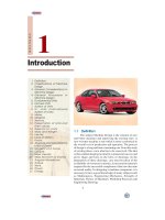
The worm and worm gear in mesh is shown in Fig. 31.3.
The following terms, in connection with the worm gearing, are important from the subject point
of view :
1. Axial pitch. It is also known as linear pitch of a worm. It is the distance measured axially
(i.e. parallel to the axis of worm) from a point on one thread to the corresponding point on the
adjacent thread on the worm, as shown in Fig. 31.3. It may be noted that the axial pitch (p
a
) of a worm
is equal to the circular pitch ( p
c
) of the mating worm gear, when the shafts are at right angles.
Fig. 31.3 . Worm and Worm gear.
Worm gear is used mostly where the power source operates at a high speed and output is at a slow
speed with high torque. It is also used in some cars and trucks.
1104
n
A Textbook of Machine Design
2. Lead. It is the linear distance through which a point on a thread moves ahead in one
revolution of the worm. For single start threads, lead is equal to the axial pitch, but for multiple start
threads, lead is equal to the product of axial pitch and number of starts. Mathematically,
Lead, l = p
a
. n
where p
a
= Axial pitch ; and n = Number of starts.
3. Lead angle. It is the angle between the tangent to the thread helix on the pitch cylinder and
the plane normal to the axis of the worm. It is denoted by λ.
A little consideration will show that if one complete
turn of a worm thread be imagined to be unwound from
the body of the worm, it will form an inclined plane whose
base is equal to the pitch circumference of the worm and
altitude equal to lead of the worm, as shown in Fig. 31.4.
From the geometry of the figure, we find that
tan λ =
Lead of the worm
Pitch circumference of the worm
=
WW
.
a
pn
l
DD
=
ππ
...(
3
l = p
a
. n)
=
WWW
.
..
c
pn
mn mn
DDD
π
==
ππ
...(
3
p
a
= p
c
; and p
c
= π m)
where m = Module, and
D
W
= Pitch circle diameter of worm.
The lead angle (λ) may vary from 9° to 45°. It has been shown by F.A. Halsey that a lead angle
less than 9° results in rapid wear and the safe value of λ is 12½°.
Fig. 31.4. Development of a helix thread.
Model of sun and planet gears.
INPUT
Spline to Accept
Motor Shaft
Housing OD Designed to meet
RAM Bore Dia, and Share Motor
Coolant Supply
OUTPUT- External Spline to
Spindle
Ratio Detection Switches
Hydraulic or Pneumatic Speed
Change Actuator
Round Housing With O-ring
Seated Cooling Jacket
Motor Flange
Hollow Through Bore for
Drawbar Integration
Worm Gears
n
1105
For a compact design, the lead angle may be determined by the following relation, i.e.
tan λ =
1/3
G
W
,
N
N
where N
G
is the speed of the worm gear and N
W
is the speed of the worm.
4. Tooth pressure angle. It is measured in a plane containing the axis of the worm and is equal
to one-half the thread profile angle as shown in Fig. 31.3.
The following table shows the recommended values of lead angle (λ) and tooth pressure
angle (φ).
TT
TT
T
aa
aa
a
ble 31.1.ble 31.1.
ble 31.1.ble 31.1.
ble 31.1.
Recommended v Recommended v
Recommended v Recommended v
Recommended v
alues of lead angle and pralues of lead angle and pr
alues of lead angle and pralues of lead angle and pr
alues of lead angle and pr
essuressur
essuressur
essur
e angle.e angle.
e angle.e angle.
e angle.
Lead angle (λ) 0 – 16 16 – 25 25 – 35 35 – 45
in degrees
Pressure angle(φ) 14½ 20 25 30
in degrees
For automotive applications, the
pressure angle of 30° is recommended
to obtain a high efficiency and to per-
mit overhauling.
5. Normal pitch. It is the distance
measured along the normal to the threads
between two corresponding points on
two adjacent threads of the worm.
Mathematically,
Normal pitch, p
N
= p
a
.cos λ
Note. The term normal pitch is used for a
worm having single start threads. In case of a
worm having multiple start threads, the term
normal lead (l
N
) is used, such that
l
N
= l . cos λ
6. Helix angle. It is the angle
between the tangent to the thread helix on the pitch cylinder and the axis of the worm. It is denoted by
α
W
, in Fig. 31.3. The worm helix angle is the complement of worm lead angle, i.e.
α
W
+ λ = 90°
It may be noted that the helix angle on the worm is generally quite large and that on the worm
gear is very small. Thus, it is usual to specify the lead angle (λ) on the worm and helix angle (α
G
) on
the worm gear. These two angles are equal for a 90° shaft angle.
7. Velocity ratio. It is the ratio of the speed of worm (N
W
) in r.p.m. to the speed of the worm gear
(N
G
) in r.p.m. Mathematically, velocity ratio,
V.R. =
W
G
N
N
Let l = Lead of the worm, and
D
G
= Pitch circle diameter of the worm gear.
We know that linear velocity of the worm,
v
W
=
W
.
60
lN
Worm gear teeth generation on gear hobbing machine.
1106
n
A Textbook of Machine Design
and linear velocity of the worm gear,
v
G
=
GG
60
DN
π
Since the linear velocity of the worm and worm gear are equal, therefore
W
.
60
lN
=
GG W G
G
.
or
60
DN N D
Nl
ππ
=
We know that pitch circle diameter of the worm gear,
D
G
= m . T
G
where m is the module and T
G
is the number of teeth on the worm gear.
∴ V.R. =
WG G
G
.
NDmT
Nl l
ππ
==
=
GGG
..
.
ca
a
pT pT T
lpnn
==
... (
3
p
c
= π m = p
a
; and l = p
a
. n)
where n = Number of starts of the worm.
From above, we see that velocity ratio may also be defined as the ratio of number of teeth on the
worm gear to the number of starts of the worm.
The following table shows the number of starts to be used on the worm for the different velocity
ratios :
TT
TT
T
aa
aa
a
ble 31.2.ble 31.2.
ble 31.2.ble 31.2.
ble 31.2.
Number of star Number of star
Number of star Number of star
Number of star
ts to be used on the wts to be used on the w
ts to be used on the wts to be used on the w
ts to be used on the w
oror
oror
or
m fm f
m fm f
m f
or difor dif
or difor dif
or dif
ferfer
ferfer
fer
ent vent v
ent vent v
ent v
elocity raelocity ra
elocity raelocity ra
elocity ra
tiostios
tiostios
tios.
Velocity ratio (V. R.) 36 and above 12 to 36 8 to 12 6 to 12 4 to 10
Number of starts or
threads on the worm Single Double Triple Quadruple Sextuple
(n = T
w
)
31.531.5
31.531.5
31.5
PrPr
PrPr
Pr
oporopor
oporopor
opor
tions ftions f
tions ftions f
tions f
or or
or or
or
WW
WW
W
oror
oror
or
msms
msms
ms
The following table shows the various porportions for worms in terms of the axial or circular
pitch ( p
c
) in mm.
TT
TT
T
aa
aa
a
ble 31.3.ble 31.3.
ble 31.3.ble 31.3.
ble 31.3.
Pr Pr
Pr Pr
Pr
oporopor
oporopor
opor
tions ftions f
tions ftions f
tions f
or wor w
or wor w
or w
oror
oror
or
m.m.
m.m.
m.
S. No. Particulars Single and double Triple and quadruple
threaded worms threaded worms
1. Normal pressure angle (φ) 14½° 20°
2. Pitch circle diameter for 2.35 p
c
+ 10 mm 2.35 p
c
+ 10 mm
worms integral with the shaft
3. Pitch circle diameter for 2.4 p
c
+ 28 mm 2.4 p
c
+ 28 mm
worms bored to fit over the shaft
4. Maximum bore for shaft p
c
+ 13.5 mm p
c
+ 13.5 mm
5. Hub diameter 1.66 p
c
+ 25 mm 1.726 p
c
+ 25 mm
6. Face length (L
W
) p
c
(4.5 + 0.02 T
W
) p
c
(4.5 + 0.02 T
W
)
7. Depth of tooth (h) 0.686 p
c
0.623 p
c
8. Addendum (a) 0.318 p
c
0.286 p
c
Notes: 1. The pitch circle diameter of the worm (D
W
) in terms of the centre distance between the shafts (x) may
be taken as follows :
D
W
=
0.875
()
1.416
x
... (when x is in mm)
Worm Gears
n
1107
2. The pitch circle diameter of the worm (D
W
) may also be taken as
D
W
=3 p
c
, where p
c
is the axial or circular pitch.
3. The face length (or length of the threaded portion) of the worm should be increased by 25 to 30 mm for
the feed marks produced by the vibrating grinding wheel as it leaves the thread root.
31.631.6
31.631.6
31.6
Pr Pr
Pr Pr
Pr
oporopor
oporopor
opor
tions ftions f
tions ftions f
tions f
or or
or or
or
WW
WW
W
oror
oror
or
m Gearm Gear
m Gearm Gear
m Gear
The following table shows the various proportions for worm gears in terms of circular pitch
( p
c
) in mm.
TT
TT
T
aa
aa
a
ble 31.4.ble 31.4.
ble 31.4.ble 31.4.
ble 31.4.
Pr Pr
Pr Pr
Pr
oporopor
oporopor
opor
tions ftions f
tions ftions f
tions f
or wor w
or wor w
or w
oror
oror
or
m gearm gear
m gearm gear
m gear
..
..
.
S. No. Particulars Single and double threads Triple and quadruple threads
1. Normal pressure angle (φ) 14½° 20°
2. Outside diameter (D
OG
) D
G
+ 1.0135 p
c
D
G
+ 0.8903 p
c
3. Throat diameter (D
T
) D
G
+ 0.636 p
c
D
G
+ 0.572 p
c
4. Face width (b) 2.38 p
c
+ 6.5 mm 2.15 p
c
+ 5 mm
5. Radius of gear face (R
f
) 0.882 p
c
+ 14 mm 0.914 p
c
+ 14 mm
6. Radius of gear rim (R
r
) 2.2 p
c
+ 14 mm 2.1 p
c
+ 14 mm
31.731.7
31.731.7
31.7
EfEf
EfEf
Ef
ff
ff
f
iciencicienc
iciencicienc
icienc
y of y of
y of y of
y of
WW
WW
W
oror
oror
or
m Gearm Gear
m Gearm Gear
m Gear
inging
inging
ing
The efficiency of worm gearing may be defined as the ratio of work done by the worm gear to
the work done by the worm.
Mathematically, the efficiency of worm gearing is given by
η =
tan (cos tan )
cos tan
λφ−µλ
φλ+µ
...
(i)
where φ = Normal pressure angle,
µ = Coefficient of friction, and
λ = Lead angle.
The efficiency is maximum, when
tan λ =
2
1
+µ −µ
In order to find the approximate value of
the efficiency, assuming square threads, the
following relation may be used :
Efficiency, η =
tan (1 – tan )
tan
λµλ
λ+µ
1tan
1/tan
−µ λ
=
+µ λ
1
tan
tan ( )
λ
=
λ+φ
...(Substituting in equation
(i), φ = 0, for
square threads)
where φ
1
= Angle of friction, such
that tan φ
1
= µ.
A gear-cutting machine is used to cut gears.
1108
n
A Textbook of Machine Design
The coefficient of friction varies with the speed, reaching a minimum value of 0.015 at a
rubbing speed
.
cos
WW
r
DN
v
π
=
λ
between 100 and 165 m/min. For a speed below 10 m/min, take
µ = 0.015. The following empirical relations may be used to find the value of µ, i.e.
µ =
0.25
0.275
,
()
r
v
for rubbing speeds between 12 and 180 m/min
=
0.025
18000
r
v
+
for rubbing speed more than 180 m/min
Note : If the efficiency of worm gearing is less
than 50%, then the worm gearing is said to be
self locking, i.e. it cannot be driven by applying
a torque to the wheel. This property of self
locking is desirable in some applications such
as hoisting machinery.
Example 31.1. A triple threaded
worm has teeth of 6 mm module and pitch
circle diameter of 50 mm. If the worm gear
has 30 teeth of 14½° and the coefficient of
friction of the worm gearing is 0.05, find
1. the lead angle of the worm, 2. velocity
ratio, 3. centre distance, and 4. efficiency
of the worm gearing.
Solution. Given : n = 3 ; m = 6 ;
D
W
= 50 mm ; T
G
= 30 ; φ = 14.5° ;
µ = 0.05.
1. Lead angle of the worm
Let λ = Lead angle of the worm.
We know that tan λ =
W
.63
0.36
50
mn
D
×
==
∴λ= tan
–1
(0.36) = 19.8°
Ans.
2. Velocity ratio
We know that velocity ratio,
V.R.=T
G
/ n = 30 / 3 = 10
Ans.
3. Centre distance
We know that pitch circle diameter of the worm gear
D
G
= m.T
G
= 6 × 30 = 180 mm
∴ Centre distance,
x =
WG
50 180
115 mm
22
DD
+
+
==
Ans.
4. Efficiency of the worm gearing
We know that efficiency of the worm gearing.
η =
tan (cos tan )
cos . tan
λφ−µλ
φλ+µ
=
tan 19.8 (cos 14.5 0.05 tan 19.8 )
cos 14.5 tan 19.8 0.05
°°−×°
°× °+
=
0.36 (0.9681 0.05 0.36) 0.342
0.858 or 85.8%
0.9681 0.36 0.05 0.3985
−×
==
×+
Ans.
Hardened and ground worm shaft and worm wheel
pair
Worm Gears
n
1109
Note : The approximate value of the efficiency assuming square threads is
η =
1 – tan 1 0.05 0.36 0.982
0.86 or 86%
1 /tan 1 0.05/0.36 1.139
µλ − ×
===
+µ λ +
Ans.
31.831.8
31.831.8
31.8
Str Str
Str Str
Str
ength of ength of
ength of ength of
ength of
WW
WW
W
oror
oror
or
m Gear m Gear
m Gear m Gear
m Gear
TT
TT
T
eetheeth
eetheeth
eeth
In finding the tooth size and strength, it is safe to assume that the teeth of worm gear are always
weaker than the threads of the worm. In worm gearing, two or more teeth are usually in contact, but
due to uncertainty of load distribution among themselves it is assumed that the load is transmitted by
one tooth only. We know that according to Lewis equation,
W
T
=(σ
o
. C
v
) b. π m . y
where W
T
= Permissible tangential tooth load or beam strength of gear tooth,
σ
o
= Allowable static stress,
C
v
= Velocity factor,
b = Face width,
m = Module, and
y = Tooth form factor or Lewis factor.
Notes : 1. The velocity factor is given by
C
v
=
6
,
6 v+
where v is the peripheral velocity of the worm gear in m/s.
2. The tooth form factor or Lewis factor (y) may be obtained in the similar manner as discussed in spur
gears (Art. 28.17), i.e.
y =
G
0.684
0.124 ,
T
−
for 14½° involute teeth.
=
G
0.912
0.154 ,
T
−
for 20° involute teeth.
3. The dynamic tooth load on the worm gear is given by
W
D
=
T
T
6
6
v
Wv
W
C
+
=
where W
T
= Actual tangential load on the tooth.
The dynamic load need not to be calculated because it is
not so severe due to the sliding action between the worm and
worm gear.
4. The static tooth load or endurance strength of the tooth
(W
S
) may also be obtained in the similar manner as discussed
in spur gears (Art. 28.20), i.e.
W
S
= σ
e
.b π m.y
where σ
e
= Flexural endurance limit. Its
value may be taken as 84 MPa
for cast iron and 168 MPa for
phosphor bronze gears.
31.9 31.9
31.9 31.9
31.9
WW
WW
W
ear ear
ear ear
ear
TT
TT
T
ooth Load footh Load f
ooth Load footh Load f
ooth Load f
or or
or or
or
WW
WW
W
oror
oror
or
m Gearm Gear
m Gearm Gear
m Gear
The limiting or maximum load for wear (W
W
) is
given by
W
W
= D
G
. b . K
where D
G
= Pitch circle diameter
of the worm gear,
Worm gear assembly.