Tài iệu Photoshop cs5 by Dayley part 103 pdf
Bạn đang xem bản rút gọn của tài liệu. Xem và tải ngay bản đầy đủ của tài liệu tại đây (295.64 KB, 8 trang )
Chapter 23: Using the 3D Panel to Edit 3D Scenes and Settings
735
Quality
Again you are given the opportunity to improve the quality of your rendering by sacrificing pro-
cessing time. This option is set by default to render your 3D object in Interactive (painting) mode
so that as you manipulate and edit your objects, you are working with them in real time rather
than waiting after each move for your object to be re-rendered. When you are finished creating,
manipulating, and adding texture to your object, you want the final draft to be rendered in the
highest quality possible. At this point, choose Ray Traced Final Draft from the Quality drop-down
menu. This process takes several minutes at best, so be sure you are ready to complete the final
rendering.
Paint On
The Paint On option allows you to choose a texture to use to paint on using the 3D paint mode. If
you choose a texture that has not been created for your object, Photoshop creates it for you.
Painting on these textures doesn’t actually leave painted pixels behind; it just makes changes to the
texture. When you paint on a glossy texture, for instance, you make changes to the glossiness of
your 3D object.
Global Ambient Color
Double-click the Global Ambient Color swatch to change the color of the reflective surfaces in your
3D scene. This light doesn’t cast any direct light or shadows, but it can add a cool or warm tone to
your scene.
Creating cross sections
Creating a cross section is another very versatile option found in the scene settings within the 3D
panel. A cross section is created by cutting into a 3D object and looking into it. Cross sections have
several varied uses.
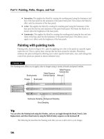
Cross sections are great for use with architectural renderings. A cross section allows you to see
inside the models of 3D buildings. You can see in Figure 23.9 that I cut the roof off this simple
room to show you the inside of it. You can see that this could be a very valuable application for
looking at or editing more complex buildings or furnished rooms.
You also can use cross sections to cut down any 3D model for use in a composite. You can inter-
sect a cross-sectioned object with another object or image, or you can just use the cut down ver-
sion of an object. By using two instances of the same 3D model, you can open a previously solid
object, such as a box, by creating matching cross sections.
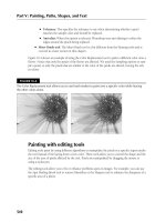
Select the Cross Section box in the Render Settings area of the 3D panel to get started. Your 3D
object is cut exactly in half along the X axis, as shown in Figure 23.10. Using the settings, you can
create a cross section on any plane, position it anywhere on your object, and tilt it from side to side
or back to front.
33_584743-ch23.indd 73533_584743-ch23.indd 735 5/3/10 10:44 AM5/3/10 10:44 AM
Part VII: Working with 3D Images
736
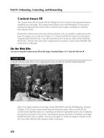
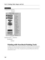
FIGURE 23.9
This room had a roof before a cross section was created.
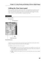
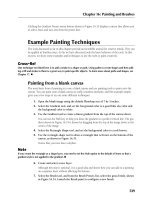
FIGURE 23.10
Clicking the Cross Section box starts you out by cutting your object exactly in half.
33_584743-ch23.indd 73633_584743-ch23.indd 736 5/3/10 10:44 AM5/3/10 10:44 AM
Chapter 23: Using the 3D Panel to Edit 3D Scenes and Settings
737
When you create a cross section, you can set the following options:
l
Plane: When this box is selected, a plane is created that is a visual aid showing you
exactly how the cross section is cutting your object in two. You probably want to keep the
plane on while you are adjusting the settings for your cross section in order to give your-
self a guide to what you are doing. You can change the color or opacity of the plane.
l
Intersection: Click this box to outline the areas of the object that have been affected by
the cross section. You can change the color of the outline by clicking the color box and
making the change.
l
Flip: Check this box to determine which half of the object to show. If I had checked this
option when I created the cross section for Figure 23.9, I would have seen the roof of the
house, instead of the floor.
l
Offset: When you enable a cross section, your 3D object is cut exactly in half. By chang-
ing the offset, you can move that dividing line to cut off more or less of your object.
l
Tilt: The tilt settings change the angle of the cross section. By default, the angle of the cut
is parallel with the base of your object. Tilt A changes the angle of the cross section front
to back, and Tilt B changes the angle side to side.
l
Axis: You can click any of the axis indicators to change the cross section to the indicated
axis. The room in Figure 23.9 is cut along the Z-axis, while the balloon in Figure 23.10 is
cut along the X-axis.
Toggle the 3D extras
You can change the view of your 3D scene using the Toggle the 3D Extras icon at the bottom of the
3D panel, as seen in Figure 23.11. You can use the drop-down menu that appears when you click
the icon to change the visibility of these features in your 3D workspace:
FIGURE 23.11
Toggle the visibility of these options on or off
33_584743-ch23.indd 73733_584743-ch23.indd 737 5/3/10 10:44 AM5/3/10 10:44 AM
Part VII: Working with 3D Images
738
l
3D Axis: This option toggles the visibility of the 3D Axis Widget. The widget has its own
menu bar with the option to close the widget. After you’ve closed it, however, the easiest
way to bring it back up is to select this option.
l
3D Ground Plane: In order to catch shadows and help to set perspective, a ground plane
has been placed in the 3D workspace in Photoshop. You can see what it looks like when
you turn it on in Figure 23.12. You can’t edit or adjust this ground plane as you would be
able to do in a 3D modeling program, but you can move your 3D objects in relation to it.
For instance, you can lift your objects up off of the ground plane, and the shadows falling
from them reflect the idea that your object is floating.
FIGURE 23.12
Turning on the visibility of the ground plane makes it easy to manipulate your object in
relation to it.
l
3D Light: Normally, you wouldn’t want to see the lights in your scene, but as you are
placing and adjusting them, they are so much easier to work with if you toggle their visi-
bility on.
l
3D Selection: This option allows you to toggle the visibility of the bounding box around
your 3D object.
33_584743-ch23.indd 73833_584743-ch23.indd 738 5/3/10 10:44 AM5/3/10 10:44 AM
Chapter 23: Using the 3D Panel to Edit 3D Scenes and Settings
739
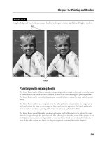
3D {Mesh} Panel
When you want to concentrate on making changes to the 3D object itself, select the Meshes filter
icon from the 3D panel. This shows the 3D {Mesh} panel, as shown in Figure 23.13. The 3D mesh
is the object itself—no textures, no lights, just the edges and vertices that make up the shape and
form of the object. Some objects have more than one mesh. By selecting an individual mesh, you
can manipulate it and edit its properties.
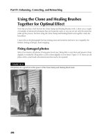
FIGURE 23.13
The 3D {Mesh} panel
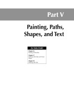
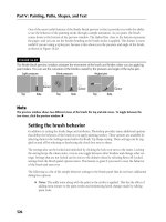
The sword shown in Figure 23.14 contains the five meshes shown in Figure 23.13. These meshes
include the blade, the grip, the guard, the pommel, and the tiny button on top of the pommel. You
can select any one of these meshes from the 3D layers and change these settings:
l
Catch Shadows: Selecting this setting allows your object to catch shadows that are cast by
other objects in your scene.
l
Cast Shadows: This allows your object to cast shadows. In order for your object to catch
or cast shadows, at least one light must be placed in your scene.
l
Invisible: This option turns off the visibility of the selected mesh, but leaves the shadows
cast on the surface of the mesh behind.
l
Shadow Opacity: This setting allows you to set the shadow opacity higher or lower to
cast harder or softer shadows.
33_584743-ch23.indd 73933_584743-ch23.indd 739 5/3/10 10:44 AM5/3/10 10:44 AM
Part VII: Working with 3D Images
740
FIGURE 23.14
This 3D sword contains five different meshes.
Note
You can rename a mesh, or any other 3D layer, by double-clicking its name.
n
Under the options in the settings area of the 3D panel, you see information displayed about the
mesh you have selected. You see the number of materials and textures applied to your mesh, as
well as the number of vertices and faces that make up your mesh.
You can move and manipulate individual meshes using the Mesh tool in the 3D panel. You can use
this tool in any of the 3D panels actually, and it doesn’t matter if you have a single mesh selected in
the 3D {Mesh} panel. When you select the Mesh tool, you see the options bar change to reflect the
different mesh tools, as shown in Figure 23.15, just as it did when you selected the 3D object or
camera tools in the Toolbox.
33_584743-ch23.indd 74033_584743-ch23.indd 740 5/3/10 10:44 AM5/3/10 10:44 AM
Chapter 23: Using the 3D Panel to Edit 3D Scenes and Settings
741
FIGURE 23.15
The 3D Mesh tool found in the 3D panel is very similar to the 3D Object tool found in the Toolbox.
To use these tools, hover over the mesh that you want to manipulate with the selected tool. A
bounding box appears around the mesh, as shown in Figure 23.16. Click and drag to make
changes to the mesh, just as you would with the 3D Object or Camera tools.
FIGURE 23.16
I can manipulate the sword’s guard by hovering over it with the Mesh Rotate tool until the bounding box
appears.
Note
When the Mesh tool is selected, you can use the widget to manipulate meshes as well. The widget manipulates
the mesh layer that is selected in either the 3D {Scene} panel or the 3D {Mesh} panel.
n
33_584743-ch23.indd 74133_584743-ch23.indd 741 5/3/10 10:44 AM5/3/10 10:44 AM
Part VII: Working with 3D Images
742
3D {Materials} Panel
You can apply several texture maps to each mesh associated with your object. These texture maps
control the color, texture, and highlights of your object. These textures taken together constitute
the material associated with a particular mesh. When you have several meshes in a 3D scene, you
also have several materials associated with that scene. When you have the 3D {Materials} panel
open, you work closely with the Layers panel to make changes to the look of your object.
Figure 23.17 shows the 3D {Materials} panel along with the Layers panel associated with the wine
bottle that can be created from the 3D presets. You can see that three textures and three materials
are associated with the bottle. This is deceptive, because you might think they are the same thing,
but I take you through a couple of exercises to not only demonstrate the difference between them,
but show you how you can make changes to them.
FIGURE 23.17
The 3D {Materials} panel lists the materials associated with your 3D object, and the Layers panel lists the
textures.
Editing textures
Textures are embedded layers in your 3D object. You can edit them by double-clicking the layer in
the Layers panel. This brings up the image file used to create the texture. Make changes to the
image file and save it. The changes are immediately reflected on your 3D object.
33_584743-ch23.indd 74233_584743-ch23.indd 742 5/3/10 10:44 AM5/3/10 10:44 AM