Summary of doctoral thesis: Improving the efficiency in using double fed induction machine in shaft generator system on shipboards
Bạn đang xem bản rút gọn của tài liệu. Xem và tải ngay bản đầy đủ của tài liệu tại đây (1.35 MB, 26 trang )
MINSTRY OF EUCATION AND TRANING
HANOI UNIVESITY TRANSPORT AND COMMUNICATIONS
NGUYEN TRONG THANG
IMPROVING THE EFFICIENCY IN USING DOUBLE-FED
INDUCTION MACHINE IN SHAFT GENERATOR SYSTEM ON
SHIPBOARDS
Major: Technology of Control and Automation
Code: 62.52.02.16
SUMMARY OF DOCTORAL THESIS
HÀ NỘI- 2014
The thesis was completed at: Hanoi University of Transport and
Communications
Supervisor:
1. Ass.Prof. Dr Nguyen Tien Ban
2. Ass.Prof. Dr Nguyen Thanh Hai
Reviewer 1:..........................................................................................................
..............................................................................................................................
Reviewer 2:..........................................................................................................
..............................................................................................................................
Reviewer 3:..........................................................................................................
..............................................................................................................................
This thesis will be defended at Universitarian dissertation Committee at
University of Transport and Communications.
At ….hour…..date.…month….year.
The thesis can be found at: National Library Library of University of
Transport and Communications.
1
INTRODUCTION
Brief
The thesis studies the shaft generator system using doubly-fed induction
machine on power-station on shipboards for providing solutions to improve
the efficiency of energy production and saving operating costs on shipboards.
The thesis consists of: 4 chapters, 113 pages, 97 references, 54 figures and
graphs.
Rationale
While running on the sea, on the stable environment in climate and
weather, the main engine propeller of shipboard often is not at full power
mode, to take advantage of this excess power, the large shipboard often is
designed with shaft generator working together with the diesel-generator.
However, one of the complex technical issues is the stabilizing in
frequency and voltage of the shaft generator when the speed of the main
machine changing with the large limit, one of the effective technical solution
is that using doubly-fed induction machine working in generator mode.
The advantages of DFIG in the power generation systems is that the
stator is connected directly to the grid and the rotor is connected to the
grid through the control circuit. Because the control circuit is in the rotor,
the power of the control circuit is much less than the power fed in to the grid,
and the generating power is fed into the grid directly.
Because of the above reasons, the author chose title “Improving the
efficiency in using doubly-fed induction machine in shaft generation system
on shipboards” to perform the thesis.
Aims
The application of doubly-fed induction machine on power-station on
shipboard ensures that the two work modes: 1.Working in parallel with the
grid of shipboard; 2.Work independently when requiring. In the thesis, the
authors delve into the ability to work in parallel with the shipboard grid by
proposing a new structure with a simple control system, which is high quality,
stable imitation of the grid voltage.
In the thesis, the author also presents the method of caculating optimum
angular speed of DFIG rotor so that the conversion efficiency from
mechanical engergy into electrical energy in shaft generators on shipboards is
maximal. Hence, the transmission system between the main engine and DFIG
rotor with the reasonable ratio of transmission is designed in order that the
2
consumption of fuel for producing one electrical unit in shaft generators used
DFIG is minimum.
The subject and scope of research
The subject of thesis include of:
- The doubly-fed induction machine.
- The control system structure of the doubly-fed induction machine in shaft
generator.
The scope of thesis: Researching the shaft generator working in parallel
with the grid on shipboard.
Results
- The results of scientific is that proposing the new control structure of the
doubly-fed induction machine in shaft generator on shipboards, improving the
efficiency in using doubly-fed induction machine in shaft generation system
on shipboards.
- The results of practical is that reducing the consumption of fuel for
producing one electrical unit in shaft generators used DFIG, which plays an
important role in saving operating costs on shipboards.
*****************
CHAPER 1: OVERVIEW OF SHAFT GENERATOR SYSTEM ON
SHIPBOARD USING DOUBLE FED INDUCTION MACHINE AND
RELATED RESEARCHS
1.1 Overview of shaft generator on shipboard
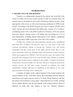
Figure 1.1: The system structure of shaft generator using
doubly-fed induction machine
The symbols in Figure 1.1 are as follows: 1.Propeller; 2.Shaft generator;
3.Gearbox; 4. Main machine; 5.The controller of shaft generator power; 6.The
power distribution cabinet; 7.The diesel-generator.
1.2 The shaft generation systems in practices
3
1.2.1 The ways to layout for shaft generator to receive the energy from
main machine
1.2.2 The electrical structure of of shaft generator
1.3 The general diagram of the control system of shaft generator using
doubly-fed induction machine
The control circuit has two main parts: The grid-side converter control
system and the rotor-side converter control system, two parts are connected
together through the DC circuit.
Figure 1.11: The tructure of control system of
doubly-fed induction machine in shaft generator
1.4 Summary of the research results and the applications of DFIG in
generation systems
Currently, the generator system used DFIG occupies close to 50% of the
wind energy market [48], include of 93 models of various manufacturers
around the world [71].
There are many national and international researchs on DFIG control, the
control structure typicals are as following.
1.4.1 The scherbius static control structure
The first two systems using the structure Scherbius are: 1.The static
Kramer structure [23][46][85][91]; 2.The cycloconverter connected between
the stator and the rotor.
1.4.2 Space vector control
Some of national and international researches on DFIG control base on
space vector for the shaft generator are [1][2][6][27],
In addition, there are many related researches or is the similar researches,
which are researches on the generator wind used DFIG.
4
1.4.3 The direct torque control technique (DTC)
The advantage this method is the good performance of the energy
conversion [14][15][18][22][73][74][90]. ABB has developed the power
converter to control DFIG using this technique [92].
1.4.4 The direct power control technique (DPC)
The structure of DPC follows the same philosophy of DTC, but it also
looks at the effect of the stator and rotor fluxes upon the stator active and
reactive power into the grid [13][79][85][90].
1.4.5 The sensorless control structure of DFIG
There are some methods of DFIG sensorless control are as below:
The
model
reference
adaptive
system
observers
[16][25][28][30][34][40][61][66][83].
- The open-loop sensorless methods[17] [20] [32][41][57].
- The other sensorless control structure of DFIG.
1.4.6 Brushless- Doubly–Fed Induction Generator (BDFIG)
The disadvantages of the generator system using DFIG are slip rings and
carbon brushes. A structure is proposed to overcome this disadvantage is the
combination of DFIG called Brushless- Doubly–Fed Induction Generator, this
system has been feasible applied in practice [19][21][78][89][96].
1.5 The problem and proposing solution, objective of thesis
The thesis proposes the new control structure of the doubly-fed induction
machine in shaft generator on shipboards basing on the rotor similar signal
method. The control structure of the doubly-fed induction machine will be
simplified. Moreover, applying this method will improve the quality of the
shaft generator on shipboards
The thesis also researches and calculates the range of angular speed of the
doubly-fed induction machine so that the conversion efficiency from
mechanical energy into electrical energy in shaft generators on shipboards is
maximal. Hence, the transmission system between the main engine and the
rotor of the doubly-fed induction machine with the reasonable ratio of
transmission is designed in order that the consumption of fuel for producing
electrical power in shaft generators is minimal
1.6 The content and methodology of the thesis
The content of the thesis researches on the shaft generator systems using
DFIG on shipboard. Then, proposing the solution to improve the efficiency in
using doubly-fed induction machine in shaft generation system on shipboards.
5
The research methodology of the thesis is based on the characteristics,
properties and mathematical model of DFIG, the characteristics of the shaft
generator on ships for analysing, and proving the new proposed model of
DFIG control with high performance. And verifing the results obtained by
simulation in Matlab software.
Comments and conclusions of Chapter 1
*****************
CHAPER 2: PROPOSING THE STRUCTURE OF SHAFT GENERATOR
USING DFIG ON THE BASIS OF SIMILAR SIGNALS FORM ROTOR
2.1 The equations of DFIG
2.2 The structure of cascade DFIG system applied in power generation
2.2.1 The structure of generator using brushless DFIG
The structure and the operation principle of the cascade DFIG:
Hình 2.3: The structure of cascade DFIG with converter on the stator
Today, this system has built on the singer frame and do not need brushes.
Hình 2.4: The Brushless-Doubly-Fed Induction Generator -BDFIG [97]
2.2.2 The structure of generator using DFIG on the basis of similar signals
from rotor
6
Hình 2.7: The structure of generator using DFIG on the basis of similar
signals from rotor
The system includes of: two doubly-fed induction machine DFIG1, DFIG2,
the stage of signal processing and the current control circuit.
The signal in all the stages of this system are similar to the voltage signals
in the rotor DFIG1. Therefore, this method is also called the control method
on the basis of similar signal from rotor.
2.3 The mathematical model of shaft generator system using DFIG on the
basis of similar signal from rotor
2.3.1 The structure and the principle of operation
Hình 2.8: The shaft generator system using DFIG
on the basis of similar signal from rotor
The system includes of:
The main machine (ME) with the shaft is connected to the shafts of
DFIG2 and DFIG1.
DFIG1: is a small capacity doubly-fed induction machine with its
function is creating the similar voltage signal in the rotor.
7
Similarity and isolation stage: is a signal amplifier circuit using
operational amplifier with high-input resistance so that the rotor of DFIG1 is
in the open circuit mode
Current control circuit: to create the currents fed into the rotor of
DFIG. At this stage, the value of the output current is equal to the value of the
input voltage signal.
DFIG2: is the doubly-fed induction generator, and its function is
creating the voltages and the currents which are fed into the grid.
Shafts of DFIG1 and DFIG2 are tightly connected to each other to make
the angles of their stators and rotors equal.
Because there are two doubly-fed induction machines in the system so the
parameters are presented as: 1Y for DFIG1, 2Y for DFIG2.
2.3.2 The mathematical model of DFIG1 and DFIG2
On axis oriented along the grid-voltage vector position, the equations of
voltage vector and the stator flux vector of DFIG1 are presented as below:
1 f 1 1 f d (1 f )
1
f
s
j. s . s
u s Rs . i s
dt
1
f
1 u f 1R .1 i f d ( r ) j. .1 f
r
r
r
r
r
dt
1 f 1 f
1 f 1
1
s i s . Ls i r . Lm
1 f 1 f
r i s .1 Lm 1 i rf .1 Lr
( 2 . 65 .a , b , c , d )
Because of the hight resistance of the similarity and isolation stage, the
rotor of DFIG1 works in the open circuit mode, so 1 i rf 0 ,the flux vector of
stator and rotor of DFIG1 are as below:
1 f 1 i sf .1 L s
s
1 f 1 f 1
r i s . Lm
( 2 .66 .a , b )
The equations of the stator and rotor voltage of DFIG1 are as below:
1 f 1 1 f 1 d (1 i sf )
1 f
j. s .1 Ls . i s
u s R s . i s Ls .
dt
1 f
1 u f 1L d ( i s ) j. .1 L .1 i f
s
r
m
r
m
dt
( 2 .67 .a , b )
2.3.3 The system model of DFIG2 before connecting stator of DFIG2 to
the grid
When the stator of DFIG2 is not connected to the grid, 2 i sf 0 , the flux
vector of stator and rotor of DFIG2 are as below:
8
2 f 2 i rf 0 .2 Lm
s
2 f 2 f 2
r i r 0 . Lr
( 2 . 69 .a , b )
The equations of the stator and rotor voltage of DFIG2 are as below:
2 f
2 f 2
d ( ir0 )
2 f
j. s .2 Lm . i r 0
u s Lm .
dt
2 f
2 u f 2 R .2 i f 2L . d ( i r 0 ) j. .2 L .2 i f
r0
r0
r
r
r
r
r
dt
( 2 . 70 .a , b )
The output voltage of the DFIG1 rotor (in equation 2.65b) goes through to
f
the similarity and isolation stage, then generates the voltage u ss is as below:
1 f
f
1
f
u ss Gss . u r Gss .(1Lm .
d( i s )
1 f
j.r .1Lm . i s )
dt
( 2 . 71 )
In the voltage modulation of DFIG2 rotor, offset component 2 R r .2 i rf 0 ,
Therefore the votage into the rotor of DFIG2:
1 f
2
f
1
f
2 f
2 f
ur u ss 2Rr . i r0 2Rr . i r0 Gss (1Lm
d( i s )
1 f
j.r .1Lm. i s )
dt
( 2 . 72 )
Compare with the rotor voltage equation of DFIG2 in equation (2.70b):
1 f
2
2 f
Rr . i r 0 Gss (1Lm .
2 f
d( i s )
d ( i r0 )
1 f
2 f
2 f
j.r .1 Lm . i s ) 2Rr . i r 0 2Lr .
j.r .2 Lr . i r 0
dt
dt
=> 2 i rf0 K 12 .1 i sf
(với K 12 G ss .1 L m / 2 L r )
( 2 . 73 )
Replace 2 i rf0 K 12 .1 i sf into equation (2.70a), we receive the stator voltage of
DFIG2:
1 f
2
u fs K12 (2Lm .
d( is )
1 f
j.s .2 Lm . i s )
dt
( 2 . 74 )
Research the equation (2.65a), which is the equation of stator voltage of
1 f
DFIG1: 1 u fs 1Rs .1 i sf 1Ls . d ( i s ) j. s .1 Ls .1 i sf
( 2 .65 .a )
dt
We have the remarks as follows:
1 f
u s is the grid voltage.
The phase difference between
1 f
1
f
u sl 1Ls .
d( is )
1 f
j. s .1 Ls . i s
dt
and the
1 f
component of grid voltage 1 u fs 1Rs .1 i sf 1Ls . d ( i s ) j.s .1 Ls .1 i sf is const.
dt
1
2
u / u K12. Lm / Ls const, so that the phase of
f 1 f
s
sl
2
1
f
u sl .
We have the results as follows:
2
u
f
s
are equal to those of
9
The phase difference between the output voltage of DFIG2 and the
grid voltage is very small and const.
Because the phase difference is const, so it can be compensated by
rotating the shaft between DFIM and DFIG. Or, the phase difference is very
small it can be neglected.
We can adjust the amplitude of the output voltage of the DFIG to be
equal to the amplitude of the grid voltage by adjusting Gss.
The components of the current in the rotor of the DFIG:
The component of the d axis current DFIG2 2ird 0 is created by adding phase
to
2
f
i r0
an angles π/2. The component of the q axis current DFIG2 2irq0 is
created by reverse-phase 2 i rf 0 .
2.3.4 The system model of DFIG2 after connecting stator of DFIG2 to
the grid
On axis oriented along the grid-voltage vector, the DFIG feeds the grid
with the current 2 i sf , the rotor current vector of the DFIG has to be evaluated as
f
follows: 2 i rf 2 i rf 0 2 i rt ,
The equations of the current components along the d and q axis:
2isd (2Lm / 2Ls )2irtd
2
2
2
2
isq ( Lm / Lm ) irtq
( 2 .85 .a , b )
Controlling the power:
The active and the reactive power of the stator of the DFIG are as:
2
2
P (3 / 2). u sd . isd
2
2
Q (3 / 2). u sd . isq
Replace
2
isd
( 2 .89 .a , b )
(2.85a) and 2isq (2.85b) into equations (2.89.a,b):
2
2
2
2
P (3 / 2). u sd . irtd .( Lm / Ls )
2
2
2
2
Q (3 / 2). u sd . irtq .( Lm / Ls )
( 2 .90 .a , b )
As can be seen in section 2.3.3:
2irtd GP .2 ird 0
2
2
irtq GQ . irq 0
( 2 .91 .a , b )
(Where 2 irq 0 is created as: 2 irq 0 2 i rf0 ; and 2 ird 0 is created by rotating the
vector 2 i rf0 an angles π/2).
Replace 2irtd and 2irtq to calculate the P, Q:
10
P (3 / 2).(GP .2 ird 0 ).2 usd .(2Lm / 2Ls ) GP . X
2
2
2
2
Q (3 / 2).(GQ . irq0 ). usd .( Lm / Ls ) GQ .Y
( 2 .92 .a , b )
Where X, Y are the steady components because on axis oriented along the
grid-voltage vector position, 2usd , 2ird 0 , 2irq0 are steady.
Therefore, to adjust the active power P of the DFIG fed into the grid, we
only need to adjust GP. To adjust the reactive power Q of the DFIG fed into
the grid we only need to adjust GQ . Finally, the block diagram of the system
model connected to the grid is presented in fig 2.13:
Figure 2.13: The system tructure of the shaft generator using doubly-fed
induction machines on the basis of similar signals from
rotor after connecting to the grid
2.3.5 The advantages of the shaft generator system using doubly-fed
induction machines on the basis of similar signals from rotor
After adjusting Gss at the similarity and isolation stage, the phase,
frequency and amplitude of the output voltage of the DFIG always equal to
those of the grid voltage even when the grid voltage and the rotor speed of the
DFIG change.
Base on this method, the generation system has a simple control structure
but operates effectively. Which ensures to decouple the active and reactive
power supplied to the grid by using two separate parameters Gp and Gq.
2.4 Determining the the gear ratio of the shaft generator
2.4.1 The structure and the function of gearbox in shaft generator
2.4.2 The energys flowing through the generators
11
Figure 2.16: The structure of the energys flowing through generators
2.4.3 The component of power through generator
2.4.3.1 The power of the main engine
3M2
Pc M c . sr
2 L
s
ird irq M 0
( 2 .100 )
2.4.3.2 The stator power of DFIG
P
1
3
M
3
2
(s M sr irq )( sr ird ) s ( M sr / Ls )ird irq
2
Ls
2
( 2 .102 )
2.4.3.3 The rotor power of DFIG
2
2
P2 r P1 / s (3 / 2 ) R r (ird irq )
( 2 .107 )
The angular frequency r 0 of rotor current for P2=0 is:
r0
3 Ls
Rr
2 M sr
s
2
2
2 u sd
u sd
X
sr
P1
(where X sr s .M sr ).
So the angular speed of the rotor is:
3 Ls
Rr
2 M sr
0 s 1
2
2 u sd
isd
X
sr
P1
2
( 2 .110 )
2.4.4 The performance of the convertion mechanical energy into electrical
energy
2.4.4.1 The case of 0
The performance of the convertion mechanical energy into electrical
energy is as below:
12
P P2 H bt
H 1
Pc
( 3 / 2 ) s ( M
M 2
2
2
/ L s ) i rd i rq (3 / 2 )( s ) i rd i rq sr H bt ( 3 / 2 ) R r ( i rd i rq ) H bt
L
s
( 2 .112 )
2
3 M sr
i i M 0
2 L rd rq
s
2
sr
The derivative of performance H is as below:
'
H
2
2
P1 (1 H bt ) (3 / 2) R r (i rd i rq ) H bt
( 2 .113 )
P
1 M 0 2
s
'
H <0, so that H increases when reducing, so that in the case of 0
,H =max when the angular speed of the rotor is =0.
2.4.4.2 The case of 0
The performance of the convertion mechanical energy into electrical
energy is as below:
H
P1 P2 / H bt
Pc
M2
2
2
2
(3 / 2) s ( M sr / L s )i rd i rq (3 / 2)( s )i rd i rq sr / H bt (3 / 2) R r (i rd i rq ) / H bt
L
s
2
3 M sr
i i M 0
2 L rd rq
s
(2.115)
The derivative of performance H is as below:
'
H
2
2
P (1 1 / H bt ) (3 / 2) Rr (ird irq ) / H bt
1
( 2 .116 )
P
1 M 0 2
s
so that H increases when increasing, so that in the case of
0 , H=max the angular speed of the rotor is 0 .
'
H >0,
Combine 2 cases, we have the results: H=max the angular speed of the
rotor is:
13
3 L
R s
2 r M sr
0 s 1
2
2 u sd
isd
X
sr
P1
2
( 2 .117 )
Comments and conclusions of Chapter 2
*****************
CHAPER 3: SURVEYING BY SIMULATION TO VERIFY THE
CORRECTNESS OF THE SYSTEM PROPOSED
3.1 Introduction
3.2 The function stages of the system
Figure 3.1: The system tructure of the shaft generator using doubly-fed
induction machines on the basis of similar signals from rotor
14
3.3 Building a the model of the system
Figure 3.2: The simulation model of the system
3.4 The way to adjust and operate the system
3.4.1 Adjusting the system before connecting the stator of DFIG2 to the
grid
Setup the coefficients Gp and Gq are zero, the phase and frequency of
the DFIG2 voltage alway equal to those of the grid voltage, so we only need
to adjust the amplitude of the DFIG voltage by adjusting Gss.
3.4.2 Operating of the system after connecting the stator of DFIG2 to the
grid
To adjust the active power P of the DFIG fed into the grid, we only need to
adjust GP. To adjust the reactive power Q of the DFIG fed into the grid we
only need to adjust GQ.
3.5 The simulation the characteristics of the stages in the system
3.5.1 The simulations before connecting the stator of DFIG2 to the grid
15
The process of adjusting GSS:
time(s)
Figure 3.7: The process of adjusting Gss
When the rotor speed (ɷ) changes
changes:
time(s)
Figure 3.8: when the rotor speed ( changes
(ɷ)
16
time(s)
Figure 3.9: The grid voltage is reduced before connecting
he
the stator of DFIG2 to the grid
Before connecting the stator of DFIG2 to the grid, after adjusting Gss, the
efore
adjusting
phase, amplitude and frequency of the output voltage of the DFIG2 always
equal to those of the grid voltage, even when the rotor speed of the DFIG and
the grid voltage changes.
3.5.2 The simulation after connecting the stator of DFIG2 to the g
simulations
grid
Adjust the active power P and reactive power Q through Gp and Gq
q
separately
separately:
time(s)
Figure 3.10: Responding when GP and GQ changing
hen
17
When the rotor speed chang
changing: Setup GP và GQ are const (GP=10, GQ=0).
G
time(s)
Figure 3.11: Responding when the rotor speed change
hen
rotor
Responding when the grid voltage change
change:
time(s)
Figure 3.12: Responding when the grid voltage change
hen
18
Comments and conclusions of Chapter 3
*****************
CHAPER 4: ESTABLISHING THE CONTROL SYSTEMS FOR DOUBLE
FED INDUCTION MACHINE IN SHAFT GENERATOR SYSTME ON
SHIPBOARDS
4.1 Introduction
4.2 Identifying the structure of control object
Figure 4.2: The block diagram of the control object
4.3 Designing controllers
4.3.1 Overview of fuzzy control system
4.3.2 Designing of PID controller tuning fuzzy to control subjects
a)
b)
Figure 4.5: The system control of the components power
Considering the control channel of the active power P:
The fuzzy tuner:
The linguistic levels of the error and error derivational (e and ė) are
assigned as: negative big (NB), negative (N), zero (Z), positive (P), and
positive big (PB), with the range of each inputs are [-1 1] (pu).
The linguistic levels of the outputs (KP, KI and KD) are assigned as: very
small (VS), small (S), zero (Z), big (B), and very big (VB), with the
range of each outputs are [0 1] (pu).
Those linguistics term by triangular-shape membership functions.
The rule base is build by an expert’s experience, the rule base for KP, KI,
KD fuzzy tuner are presented in table 4.2.
Finally the outputs can be obtained using a max-min fuzzy inference and
the crisp output is calculated by centre of area method.
19
Similarly, the structure of the reactive power control system of DFIG
fed into grid is shown in figure 4.5b.
a)
b)
c)
Figure 4.6: The fuzzy tuner and the membership functions
The rule base:
Table 4.2: The rule base for KP, KI, KD fuzzy tuner
e
NB
N
Z
P
PB
KP
KI
KD
KP
KI
KD
KP
KI
KD
KP
KI
KD
KP
KI
KD
VS
VB
VS
VS
VB
VS
VS
B
S
M
B
S
M
M
M
VS
VB
VS
S
B
S
S
B
S
B
M
M
B
S
B
VS
VB
VS
S
B
S
M
M
M
B
S
B
VB
VS
VB
S
S
B
S
M
M
B
S
B
B
S
B
VB
VS
VB
M
VS
VB
M
VS
VB
VB
VS
VB
VB
VS
VB
VB
VS
VB
ė
NB
N
Z
P
PB
Figure 4.7: The relation graph of the input and output
variable in the fuzzy tuner
20
time(s)
Figure 4.9: The simulation results with PID controller fuzzy tuning
4.4 The division of load between shaft generator with the grid of
shipboard
Setup Rp=Rq=70%.
time(s)
Figure 4.11: The simulation of the division of load between shaft generator
with the grid of shipboard
21
Running the system, the results shown in figure 4.11, the active
,
power (P) and the reactive power (Q) of DFIG fed into grid always
reactive
follow the desired value such as Pset_point=0. L, Qset_point=0.
Pset_point=0.7.P Qset_point=0.7.QlL,
with time transition and time response are very small.
To have a real simulation results, the author run the system with the other
o
case as follow : the load is a squirrel asynchronous motors (code215HP
following:
215HP,
320KW, 400V, 1487RPM), the simulation results are as figure 4.12.
time(s)
Figure 4.12: The simulation results when the load is a
squirrel asynchronous motors
22
time(s)
Figure 4.
4.13: The simulation results of the clinging ability to the setpoint value
when the system is is a squirrel asynchronous motors
Comments and conclusions of Chapter 4
In summary, it can be asserted that the advantage of the rotor similar
ummary,
signal method is simple but effective
effective.
CONCLUSIONS AND RECOMMENDATIONS
Conclusions
The thesis proposes the control structure of the doubly fed induction
doubly-fed
machine in shaft generator on shipboards basing on the rotor similar signal
method. That is a new proposal of the contr ol structure of the doubly fed
control
doubly-fed
induction machine. Based on this method, the active power and the reactive
power of doubly
doubly-fed induction machine supplied to the grid will be controlled
separately; and also the control structure of the doubly fed induction machine
doubly-fed
will be simplified. Moreover, applying this method will improve the quality of
the shaft generator on shipboards such as: improving the ability to follow the
as:
soft grid voltage of the shaft generator on the shipboards when changing the
speed of main engines; improving the stability and the safety of the grid on
shipboard.
The thesis researches, proposals and calculates the range of angular speed
of the doubly fed induction machine so that the conversion efficiency from
doubly-fed
mechanical energy into electrical energy in shaft generators on shipboards is
maximal. Hence, the transmission system between the main engine and the
23
rotor of the doubly-fed induction machine with the reasonable ratio of
transmission is designed in order that the consumption of fuel for producing
electrical power in shaft generators is minimal.
The results of the thesis have contributed to the science a new method for
controlling the doubly-fed induction machine in shaft generator on shipboards
with the simple and effective control structure.
Recommendations
With these results, the thesis has improve the efficiency in using doublyfed induction machine in shaft generation system on shipboards.
However, to further improve, the author propose some the further research
directions are as follows:
Research to controll the doubly-fed induction machines on the basis of
similar signals from rotor in case of the asymmetric faulty grid.
Research to controll the doubly-fed induction machines on the basis of
similar signals from rotor in case of feeding to the load independently.