Smart Home Automation with Linux- P3 doc
Bạn đang xem bản rút gọn của tài liệu. Xem và tải ngay bản đầy đủ của tài liệu tại đây (2.38 MB, 10 trang )
CHAPTER 1 ■ APPLIANCE CONTROL
3
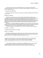
■ Note Some types of light (such as fluorescent and power-saving bulbs) cannot generally work on lamp modules
and must be used with appliance modules.
Each X10 message consists of three parts:
• A start message block (a nibble of 1110)
• An address (a house code and/or unit code)
• A command code (for example, “switch on”)
There are several different commands, fitting mainly into two groups—house code messages
directed toward all devices and unit code messages targeting a single appliance. As mentioned earlier,
each X10 module is built to accept or ignore specific messages, usually according to whether it’s
designated a lamp or appliance module; however, appliance modules will also ignore the “all lights on”
message but honor the “all units off,” which is suggested by the subtle wording of the commands
differentiating between lights and units. It is interesting to note that their inverse variants (“all lights off”
and “all units on”) do not exist. This is intentional. One of the intentions of “all lights on” was to act as a
security feature. An accidental invocation of an “all units on” command might start a teakettle dry
boiling or something similarly dangerous. Conversely, “all units off” provides a quick closedown
procedure for the house.
Once the message has been sent, nothing else happens. Ever! The receiver does not generate an
acknowledgment of the message, and the sender doesn’t query the state of the recently controlled device
to confirm its arrival. This is because the transmitting circuits are more complex and expensive than the
receiver and because adding a message facility would add cost and bulk to the simplest of light switches.
Some two-way switches do exist, providing a way for you to query their state, but they are more
expensive.
However, in an attempt to ensure data validity, the message is sent twice, and both messages are
compared for equality since electrical noise on the power line could have corrupted part of the signal.
Consequently, it takes around 0.64 seconds for an X10 message to be received. Although this is an
accepted facet of the protocol, it is not particularly friendly when guests are staying at your house, since
when they try to turn on the light, it appears to have not worked so they press the switch again and in
doing so turn it off! To overcome this, many devices have a local switch that affects the light directly,
without sending an X10 message to do so. This is mostly true for X10 light switches that act like a normal
in-wall switch but not an in-place X10 socket that is controlled by an existing (that is, normal) light
switch.
Another problem that can occur with X10 is that of dead spots, where all messages can (and
sometimes do) get swallowed because of the electrical noise generated by certain appliances. The power
supplies for some MacBooks are known to have this issue. It is therefore sometimes necessary to move
X10 devices to different sockets for them to work. X10 signals are also lost when there is a transformer in
the circuit or you have a split phase system. Again, you may need to move both the transmitter and the
receiver to the same side of the problem device.
CHAPTER 1 ■ APPLIANCE CONTROL
4
■ Note Before committing to an X10 installation, experiment with a couple of devices to ensure there is a location
in the house that is capable of issuing an X10 message that can get heard in the vital majority of other areas.
General Design
Before buying and installing any devices, you must first consider what devices you want to control and
how you want to control them. The important part of that question is not how many devices you will use
but how they will be controlled. This can be as simple or as complex as you like. And there need not be a
computer involved at all.
Simple Case
In this situation, your appliances will be controlled either by their local switches or by one or more wired
controllers plugged into the mains. A wired controller is necessary here because you always need some
way of introducing the X10 signals to the power line. There are some wired controllers (SD7233), which
include timing circuits so they can automatically turn the lights on or off at particular times of day—
sometimes within a randomized time frame to confuse potential burglars. These work well and provide a
cheaper alternative to running a computer all day, every day.
Other than the basic timer functions, this setup can only be controlled by a human making physical
contact with the controllers. It is the cheapest way to begin an exploration into X10, but appliances
cannot be controlled remotely via web sites or e-mail or wirelessly from handheld controllers.
If aesthetics are important, there are some controllers (for example, TMD4, shown later in Figure
1-11) that will fit into a wall outlet, allowing you to use the existing light switches to control multiple
lights without a Star Trek–like controller on the coffee table. However, this requires the purchase of both
an X10 switch (to send the message) and an X10 light fitting (to respond to it) and is usually overkill for
such simple setups.
Standard Case
The next step after the simple case shown earlier is to utilize wireless controllers. Most of the equipment
on the market uses radio frequency (RF, at 433MHz), allowing devices to be controlled from the garden,
through walls, through floors, and through ceilings. The precise range varies according the materials
through which the signal is traveling, the other devices operating in the 433MHz range such as TV
senders or RFID readers, and the strength of the transmitter, with some mid-price devices having a 25-
meter range when unobstructed.
Since RF has no connection to the power lines, it also requires the use of an RF-to-X10 gateway,
which plugs into a wall socket, picks up the RF signals sent by any suitable controller, and places the
data message onto the X10 power line. Although such devices have a configurable house code, their unit
code is invariably hard-coded to one, so be sure to avoid using such a code for any devices if you plan on
migrating from a simpler environment.
Adopting an RF-to-X10 gateway in this way provides a lot more scope for automation, because
controllers are wireless and no longer need to be situated next to a power socket, enabling them to
appear in bathrooms where such sockets contravene domestic housing regulations in many countries by
being within 1.5 meter of a water tap, as is the case in the United Kingdom, for example. There are RF
controllers that stick to walls, sit on desks, and even fit on key rings!
CHAPTER 1 ■ APPLIANCE CONTROL
5
The primary issue with RF remote control is that rogue transmissions are very difficult to filter out,
1
meaning someone outside could conceivably control your inside lights.
Fully Automated
The big difference between this and the standard automated example is the inclusion of a computer
interface, generally the CM11, covered later and shown in Figure 1-14. This doesn’t have an X10 address,
but it passively monitors the messages on the power lines and passes them back to the computer via the
serial or USB port. Similarly, the computer can use the device to place new messages onto the power
lines, which will be picked up by the devices you already have. Once a computer is involved, the
possibilities open up. I’ll be covering these possibilities later in this chapter when covering the range of
available X10 devices.
It is perfectly possible to have a fully automated solution using the computer that doesn’t use RF
wireless or suffer its problems. Instead of RF, you can use a more secure transport and protocol such as
HTTPS through a web browser that could be on an iPod touch, iPhone, or other suitably connected
handheld device such as a mobile phone to send the message to the computer, which is turn places
suitable data on the power line.
Assigning Addresses
Since every automated device in your house needs an address, it makes sense to assign them something
sensible and memorable at the start of the process. The most important thing to remember here is that
your X10 configuration can grow as your budget increases, and you’re more likely to add a couple of new
appliances in your house than you are to add a couple of new rooms!
Determining a house code is simple enough. If you have a neighbor, or neighbors, with an X10
setup, then pick any letter that isn’t used by them. It might sound obvious, but you should talk to them
about whether they have one and what codes they’re using. Just because you’re not seeing any irrational
behavior at the moment doesn’t mean there won’t be a conflict in the future. I would also avoid using P,
since some devices (the TM13UAH, for example) considers P as “accept message on any house code,”
which could be confusing and problematic. My only other advice here is to avoid A, which is the default
for most equipment. This has two benefits. First, it ensures that anyone “playing” with X10 devices in the
neighborhood won’t accidentally stumble onto your network and cause mischief. The second is that by
switching away from the defaults, you can be sure that the system was successfully reprogrammed and is
not working temporarily by a happy coincidence.
Producing assignments for the unit codes is a matter for your own judgment, but you cannot go far
wrong by creating a pattern. I began by numbering my devices at 2 and worked around the rooms in my
house in a counterclockwise order, starting upstairs and ending in the kitchen. I assumed two devices
per room. My reasoning and thought processes were as follows:
• Start at 2 because 1 is used by the RF-to-X10 gateway.
• Two devices per room means each room starts at 2, 4, 6, 8, and so on, which is easy
to remember.
1
A Faraday cage works but is not generally practical in a home environment!
CHAPTER 1 ■ APPLIANCE CONTROL
6
• The only time I need to know the numbers by heart is when fumbling with the
remote in the dark. This is when I’m in bed looking for a light switch. Since the
master bedroom is upstairs, I start counting upstairs. And when lying in bed, I’m
facing the rest of the house, with the second bedroom directly in front of me, and
the third to its left, which makes a counterclockwise motion more natural.
• If the split between upstairs and downstairs hadn’t occurred on unit code 8, I
would have left a gap so that it did.
• I split the lounge/dining room into two logical rooms, even though it’s one space.
This means I can have up to four devices in the one space, which is likely to
happen with larger open-plan areas.
• The kitchen is more likely to gain devices over time, so I kept that last in the list.
If you browse the selection of controllers available, you will notice that most have a selector switch
that reassigns the buttons from 1–4 to 5–8, for example, or from 1–8 to 9–16. An alternate approach is to
have the first bank (1–4, say) controlling only the lamps in the house, with the second (5–8) being used to
control the appliances in the equivalent room, making it switch between “lamps and appliance” rather
than “upstairs and downstairs.” This ensures that although the first bank is selected, it’s impossible to
accidentally turn off an appliance when you mean to control the lights, and vice versa.
The final consideration concerns the physical size of the controller modules you plan on using,
since many support only eight devices. If your most convenient numbering system happens to use
devices 9–16, then you will either have to rethink your pattern or buy only larger controllers.
Using Multiple House Codes
It is possible to have two or more house codes within a single property, bringing the total number of
household devices up to a maximum 256. That’s enough for the largest of mansions! The only
consideration with such setups is that a control message such as “all lights off” can be applied only to a
single house code. For computer-based control, you can easily adapt the software to send two (or more)
messages of the “all units off” variety, which affect all devices on the specified house code. However, if
you’ve elected to use only stand-alone remote controls, such as the desktop controllers you will learn
about later, this can require some fiddling as you switch off each house code in turn. In this case, you
would probably want to split up the house codes into the first floor, second floor, and so on, and have a
separate controller for each floor.
Device Modules
I’ll now cover the multitude of devices available on the market that can be controlled by X10, in other
words, those that contain a receiver. These break down into three categories:
Internal: Where the X10 receiver and the thing it controls are within the same
physical form factor. An example is motorized curtain rails.
Local control: The X10 receiver processes the message but controls the power to
something directly wired into it. An example is light switches.
Plug-in modules: These fit into a standard power socket, and an external device
is plugged into them. The X10 logic determines whether to allow the flow of
current between them. An example is appliance units.
CHAPTER 1 ■ APPLIANCE CONTROL
7
Controlling Lights
This is by far the most common type of device, and accordingly there are several different devices to
choose from, all known in X10 parlance as lamp modules. However, it should be noted that some lights
cannot be attached to lamp modules at all. These include the fluorescent lighting strips found in most
kitchens and their compact fluorescent lamp equivalents (often known as energy-saving bulbs) now
making their appearances in homes around the country. To make matters worse, these bulbs can also
introduce spikes on the power line that can turn off nearby X10 lights.
2
The primary functional difference between the various lamp modules is whether the device in
question supports dimming. When a light is dimmed, the alternating voltage is not reduced in
amplitude. Instead, small portions of the power sine wave are removed, which effectively turns off the
lamp for short periods of time. Consequently, the bulbs filament is charged and discharged many more
times a second than usual, which creates a changing electromagnetic field. This can result in the
filament starting to vibrate and creating an audible hum. This is not usually a problem with lightbulbs
(and you can always buy rough service bulbs that hold the filament steadier to prevent this movement),
but it is dangerous to other appliances that are not built for it.
Note that many countries are phasing out the old incandescent lightbulbs.
Lamp Module (LM12U)
This is a simple affair that requires zero installation. You simply plug it into a free wall socket, set the address
using the dials on the front, and plug your lamp into the socket on the front, as shown in Figure 1-1.
Figure 1-1. The LM12U lamp module, 122
×
52
×
42mm
2
You can witness the noise introduced by observing the oscilloscope traces shown at
CHAPTER 1 ■ APPLIANCE CONTROL
8
This will support any incandescent lamp between 60 and 300 watts and can be switched on and off
or dimmed by any X10 controller set to the same house code. The LM12U has a sister device, the AM12U,
which works in the same work. The primary difference is that the AM12U is intended for appliances and
therefore ignores any “dim” messages. The LM12U will also respond to two special messages, “all lights
on” and “all units off,” provided they are sent using a matching house code. This module, like many of
the others featured here, is placed in series with the power line acting like a logical AND gate. That is,
both the lamp’s switch and the power switch at the wall must be on for the X10 “turn on” message to
have any effect.
■ Note The code numbers given here are for the U.K. versions of these devices. Because of slightly—but
significantly—different power systems used in various countries around the world, alternate modules are required
according to your country. The LM12U in Italy, for example, is called the LM12I.
Bayonet Lamp Module (LM15EB)
This is also a simple zero-installation device but one that requires slightly more configuration. To install
it, you plug it into an existing light socket and then reinsert the bulb (up to 150W) into its free end.
Neither fluorescent lamps nor low-energy lamps should be used, though. The address is set by turning
the lamp off and on again and then pressing the required house/unit code on the controller three times,
once a second, within 30 seconds of it being switched back on. The light will come on once the code has
been learned. There is also a screw-in version of the same device (LM15ES, with ES standing for Edison
screw), although it is the bayonet version that’s shown in Figure 1-2.
Figure 1-2. The LM15EB, 45
×
45
×
95mm
CHAPTER 1 ■ APPLIANCE CONTROL
9
LM15EBs lack the dimming facility of the larger LM12U, but because they extend only 62mm farther
than a traditional fitting, they are small enough to hide inside most lamp shades, making them SWMBO-
friendly.
3
Again, the module acts like an AND gate, allowing the light to shine only when both the X10
command for “on” has been sent and the light switch would normally be on.
Wall Switch (LW10U)
As you can see from Figure 1-3, these are complete replacements for a standard light switch, which
means you are limited in styling to white plastic. However, they are easy to fit into existing recessed
switch boxes with only 16mm protruding from the wall. The unit’s address is set from a pair of dials
placed behind the rocker switch and can be accessed by gently prying it off with a screwdriver. Care
should be taken, however, because the plastic lugs that hold the switch onto the case are quite flimsy
and would only suffer three or four removals before breaking.
In addition to being controlled remotely by “on,” “off,” “dim,” and “bright” commands, the same
functionality is available locally through the switch. Touching it once switches the light to full on or off,
whereas keeping it held down will dim the light (if it is bright) or brighten it (if it is dim). Alas, the last
brightness is not kept when you switch it off and then on again, nor can you slightly increase the
brightness of a dim light without first making it fully dark, but local control means the light comes on
immediately after pressing the button so as to not confuse any guests.
Figure 1-3. The LW10U, 85
×
85
×
30mm
This device also responds to the “all lights on” and “all units off” messages for matching house
codes.
3
Most home automation enthusiasts are male, which has led to the acronym “SWMBO-friendly” being applied to any
piece of technology that is attractive, small, hidden, discrete, or invisible to a normal occupant of the house. SWMBO
stems from the British television series Rumpole of the Bailey phrase “She who must be obeyed.”
CHAPTER 1 ■ APPLIANCE CONTROL
10
MicroModule with Dimmer (LWM1)
This module is a turbocharged version of the LM10U and is shown in Figure 1-4. It works in the same
way as the LM10U but is small enough to fit inside the wall outlet, allowing you to use any switch fascia
you prefer.
Figure 1-4. The LWM1, 40
×
40
×
15mm
It supports all the existing functionality of the LM10U but can also remember the last brightness
setting, allowing the light to be smoothly changed when it’s first switched on, which helps increases the
bulb life.
■ Note The cheaper modules switch on at full brightness, so if you enjoy mood lighting, then this is a variant
worth considering.
Furthermore, this is one of the few devices in this section that supports two-way X10
communication. This means you can send a message to the device asking for its current brightness state,
and it is able to reply. This is unavailable with most other devices, meaning you (or more specifically,
your controller device) must remember the last message it sent, hoping it arrived, in order to emulate
the querying of the lamp’s state. And even this result might be flawed if the brightness was changed
locally. In most cases, however, this functionality is unnecessary because you rarely want to know
whether the light is on. If you’re going to bed, then you’re not interested is whether the light is on or not,
only whether you can switch it off. Unless you have a very large house, you can usually see a single light
on in an otherwise pitch-black house and therefore know whether you need to resend the “all units off”
message.
The downside of this device is that it costs around three times that of the LM10U. However, there is
a midrange product in the LW12 that features the same specification but without two-way
communication.
CHAPTER 1 ■ APPLIANCE CONTROL
11
DIN Rail Dimmer (LD11)
This is a (very) high-power module, capable of controlling devices up to 700W, and it is consequently
suitable for mains halogen as well as traditional mains lighting. Instead of being used in place of a switch
(like the LWM11) or in connection with the bulb (like the LM15EB), this device is remotely placed near
the fuse box, with the LD11 output cables running into the light directly. This is a switch terminal on the
LD11 that allows the appliance to be switched on and off, as if it were local. However, with four
(potentially) long cable runs from the appliance to the LD11 (two for power and two for control, as
visible in Figure 1-5), its purpose isn’t so obvious.
Figure 1-5. The LD11, 50
×
80
×
70mm
The primarily purpose for the LD11 is mood lighting, thanks to its support for halogens, and scene
lighting, thanks to its soft dimming and memory functions. Because they are generally placed away from
the devices themselves, you get a much cleaner install. The cost in cabling is thankfully offset by the
cheaper cost of the module.
If you use the LD11 to power lighting sockets, they must be used only by lamps, since the dim
feature will destroy many other types of appliance. To aid in this, you can use nonconventional plugs
and sockets for the lamps and LD11-fed outlets. If your country uses square pin plugs, source some
rounded pins, and vice versa.
Appliance MicroModule (AWM2)
This module uses the A prefix because it is primarily intended to control appliances; however, its
function is also suited to lights. The AWM2, shown in Figure 1-6, sits inside a standard wall outlet and
supports two switches. One switch controls the locally connected lightbulb (and sends an equivalent X10
message onto the power line), while the other switch sends an X10 “on” or “off” messages to the next
address in sequence. So, if your AWM2 is configured to E2, you can also control E3 from the same switch.
By installing two identically configured units at the top and bottom of the stairs, you can control both
the upstairs and downstairs lights from either location with no rewiring. And since this is an internal
module, you can use any switch facing your choose. Note, however, that this device doesn’t support
dimming.
CHAPTER 1 ■ APPLIANCE CONTROL
12
Figure 1-6. The AWM2, 46
×
46
×
18mm
Controlling Appliances
For appliances that are supplied without X10, such as teakettles, toasters, and HiFi units, a second type
of device is needed. These function in much the same way as the LM12U or LM15EB/LM15ES, whereby
the device is plugged into an existing power socket and the appliance in question is plugged into the X10
module. As mentioned previously, these require the switch on the wall socket to remain permanently on,
along with any switch on the appliance itself. This further implies that any device plugged into such a
module that could be controlled remotely must be safe at all times. In the case of the teakettles, for
example, it must contain enough water so it won’t boil dry.
Appliance Module (AM12U)
Like its sister module, the LM12U, this is a very simple “plug in and go” device that, although it looks the
same (see Figure 1-7), has three very important differences:
• It has no dimmer support.
• It can control fluorescent lights.
• It can operate at much higher loads (up to 500W for incandescent lamps, 1A for
inductive
4
appliances like fans, and 16A for resistive loads
5
such as heaters).
Consequently, its intended purpose is to automate units such as fans and teakettles. However, high-
power devices such as vacuum cleaners and fan heaters rarely work on these modules because of the
back-EMF created by the collapsing magnetic field around the motor when it is switched on or off. This
4
Inductive loads use magnetic fields and are usually characterized by motors or solenoids.
5
Resistive loads convert electrical current into other forms of energy, such as heat.