Guidelines for Engineering Design for Process Safety P2 docx
Bạn đang xem bản rút gọn của tài liệu. Xem và tải ngay bản đầy đủ của tài liệu tại đây (1.03 MB, 20 trang )
Chapter
7.
Heat
Transfer
Fluid Systems
Chapter
8.
Thermal Insulation
Chapter
9.
Process Monitoring
and
Control
Chapter
10.
Documentation
The
second
half
of the
book
deals with catastrophe avoidance through
understanding
and
controlling chemical processing hazards.
The
order
of the
chapters
in
this section
is
first)
understanding hazards, second) passive
catas-
trophe prevention systems,
and
third) active protection systems.
Chapter
11.
Sources
of
Ignition
Chapter
12.
Electrical Hazards
Chapter
13.
Deflagration
and
Detonation Flame Arresters
Chapter
14.
Pressure
Relief
Systems
Chapter
15.
Effluent
Disposal Systems
Chapter
16.
Fire Protection
Chapter
17.
Explosion Protection
During
the
development
of
these
Guidelines,
it
became clear
to the
authors
that many interrelationships exist.
It
maybe
difficult
to
address
a
safety
issue
in one
system without
affecting
several other systems.
The
difficulty
of
fixing
one
problem without creating
a
problem
in
another system
is
frequently
encountered. This overlap
is
also encountered
from
the
perspective
of
hazard
reduction:
a
single concept
can
often
be
applied
to
several systems. Because
of
these
complexities,
it is
most
effective
to
build
safety
into
the
initial design
rather than adding
it on.
Specific
references
and
applicable industry standards
arc
listed
at the end
of
each chapter. Additional sources
of
information
arc
listed under Suggested
Reading.
It is not the
intent
of
this
book
to
make
specific
design recommenda-
tions
but to
provide
a
good source
of
references where
the
interested
rcader
can
obtain more detailed information. Nomenclature
and
units
arc
given
after
each equation
(or set of
equations); tables
and
figures
adapted
from
other
sources will
use the
units
as
originally published.
A
List
of
Acronyms
and a
Glossary
arc
provided.
The
readings listed at the end of Chapter 1 arc good general sources of
information
on
chemical process
safety.
They
arc
recommended
for use in
combination with
the
CCPS
Guidelines
books.
1.5
REFERENCES
1.5.1
Regulations,
Codes
of
Practice,
and
Industry
Standards
The
editions
that
were
in
effect
when these
Guidelines
were written
are
indicated
below.
Because
standards
and
codes
are
subject
to
revision,
users
are
encouraged
to
apply
only
the
most
recent
edition.
API
(American Petroleum Institute)
RP
750.1990.
Management
of
Process
Hazards.
1st
ed.
American Petroleum
Institute,
Washington,
D. C.
29
CFR
1910.119.
Process
Safety
Management
of
Highly
Hazardous
Chemicals.
Oc-
cupational
Safety
and
Health Administration
(OSHA).
1.5.2
Specific
References
CCPS
(Center
for
Chemical
Process
Safety).
1992.
Plant
Guidelines
for
Technical
Manage-
ment
of
Chemical
Process
Safety,
American
Institute
of
Chemical Engineers,
New
York.
ISBN
0-8169-0499-5.
1.5.3
Suggested
Reading
Carson,
R. A. and C. J.
Mumford.
1988.
The
Safe
Handling
of
Chemicals
in
Industry.
2
Volumes,
Longman
Scientific
&
Technical (John Wiley
&
Sons, Inc.),
New
York.
Journal
of
Loss
Prevention
in the
Process
Industries.
Butterworth-Heinemann.
London.
King,
R.
1990.
Safety
in the
Process
Industries.
Butterworth-Heinemann, London
and
Stoneham,
MA.
King,
R.,
and J.
Magid. 1979.
Industrial
Hazard
and
Safety
Handbook.
Newnes-Butter-
worths,
London.
Lees,
F. P.
1980.
Loss
Prevention
in the
Process
Industries.
2
Volumes.
Butterworths,
London.
Loss
Prevention
Symposium
Series.
Papers presented
at the
Annual
AIChE
Loss Preven-
tion
Symposia. American Institute
of
Chemical Engineers
(AIChE),
New
York.
Process
Safety
Progress
(formerly
Plant/Operations
Progress).
T. A.
Ventrone,
ed.,
Quarterly
publication
of
American Institute
of
Chemical Engineers
(AIChE),
New
York.
Responsible
Care,
Process
Safety
Code
of
Management
Practices.
1990. Chemical Manufac-
turers Association
(CMA),
Washington,
D. C.
2
INHERENTLY
SAFER
PLANTS
2.1
INTRODUCTION
In
a
1988 report
"
Survey
of
Chemical Engineering Research: Frontiers
and
Opportunities/'
the
National Research Council
identified
inherently safer
plant
designs
as
a
critical element
for
the
continuing improvement
of
the
good
safety
record
of the
chemical
and
petrochemical industries.
The
report
par-
ticularly recognizes
the
importance
of
process
selection
on
safety,
stating that
"few
basic decisions
affect
the
hazard potential
of a
plant more than
the
initial
choice
of
technology" ("Design" 1988).
An
inherently safer plant relies
on
chemistry
and
physics—the
quantity,
properties
and
conditions
of use of the
process
materials—to
prevent injuries,
environmental damage
and
property damage rather than
on
control
systems,
interlocks, alarms
and
procedures
to
stop incipient incidents.
In the
long term,
inherently
safer
plants
are
often
the
most cost
effective.
Smaller equipment
operating
at
less severe temperature
and
pressure conditions will
be
cheaper
and
have lower operating costs.
A
process that
does
not
require complex
safety
interlocks
and
elaborate procedures will
be
simpler, easier
to
operate,
and
more reliable.
The
need
for
an
ongoing commitment
of
resources
to
maintain
the
safety
systems
will
be
eliminated.
The
safety
of
nuclear power plants relies
heavily
on
complex instrumentation
and
safety
systems,
and the
cost
as-
sociated with those systems
is
high.
Forsberg
(1990)
has
estimated that
30-60%
of
the
operating costs
of a
typical nuclear power plant
are
associated with
safety.
In
recent years there
has
been considerable interest
in
inherently safer
plants
in the
chemical process industries.
A
number
of
papers
and two
excellent
books
by
Kletz
(1983, 1984, 1989, 1990, 1991a,b,c) provide
an
over-
view
of the
general concepts
of
inherently safer plants,
and
describe many
specific
examples. Recent papers
by
Englund
(1990,1991a,b)
and
several other
authors (Althaus
and
Mahalingam
1992; Dale 1987;
Doerr
and
Hessian 1991;
Hendershot
1988,1991a;
Prugh
1992) also review inherently
safer
plants
and
processes
and
provide many
specific
examples
of
inherently
safer
designs.
Although
a
process
or
plant
can be
modified
to
increase inherent safety
at
any
time
in its
life
cycle,
the
potential
for
major
improvements
is
greatest
at
the
earliest stages
of
process development.
At
these early stages,
the
process
engineer
has
maximum degrees
of
freedom
in the
plant
and
process specifica-
tion.
The
engineer
is
free
to
consider basic process alternatives such
as
fun-
damental
technology
and
chemistry
and the
location
of the
plant. Imperial
Chemical
Industries (ICI) describes
six
stages
of
hazard
studies,
including
three during
the
process
design phase
and
three during construction, startup
and
routine plant operation.
The
identification
of
inherently
safer
process
alternatives
is
most
effectively
accomplished between
the
first
and
second
process
design hazard studies (Preston
and
Turney
1991).
At
this stage
the
conceptual plant design meets
the
general rule
for an
optimization
process—
that
a
true optimum
can be
found
only
if all of the
parameters
are
allowed
to
vary simultaneously
(Gygax
1988).
2.1.1
Process
Risk
Management
Strategies
Risk
has
been
defined
as
a
measure
of
economic
loss
or
human
injury
in
terms
of
both
the
incident likelihood
and the
magnitude
of the
loss
or
injury
(CCPS
1989).
Thus,
any
effort
to
reduce
the risk
arising
from
the
operation
of a
chemical
processing
facility
can
be
directed toward reducing
the
likelihood
of
incidents (incident frequency), reducing
the
magnitude
of the
loss
or
injury
should
an
incident occur (incident consequences),
or
some combination
of
both.
In
general,
the
strategy
for
reducing
risk,
whether directed toward
reducing
frequency
or
consequence
of
potential accidents,
falls
into
one of the
following
categories:
•
Inherent,
or
Intrinsic—Eliminating
the
hazard
by
using materials
and
process
conditions that
are
nonhazardous
(e.g.,
substituting water
for a
flammable
solvent).
•
Passive—Eliminating
or
minimizing
the
hazard
by
process
and
equip-
ment
design features that
do not
eliminate
the
hazard,
but do
reduce
either
the
frequency
or
consequence
of
realization
of the
hazard without
the
need
for any
device
to
function
actively
(e.g.,
the use of
higher
pressure rated
equipment).
•
Active—Using
controls,
safety
interlocks,
and
emergency shutdown sys-
tems
to
detect potentially hazardous process deviations
and
take correc-
tive
action. These
are
commonly referred
to as
engineering controls.
•
Procedural—Using
operating procedures, administrative checks, emer-
gency
response
and
other management approaches
to
prevent incidents,
or to
minimize
the
effects
of an
incident. These
are
commonly referred
to
as
administrative controls.
Risk
control strategies
in the
first
two
categories, inherent
and
passive,
are
more
reliable
and
robust because they depend
on the
physical
and
chemical
properties
of the
system rather than
the
successful operation
of
instruments,
devices
and
procedures. Inherent
and
passive strategies
are not the
same
and
are
often
confused.
A
truly inherently
safer
process will completely eliminate
the
hazard
(Kletz
199Ia).
The
discussion
and
examples
in
this chapter include
both inherent
and
passive strategies
to
manage
risk.
Table
2-1
gives some
Table
2-1
Examples
of
Process
Risk Management
Strategies
Risk
Management
Strategy
Category
1.
Inherent
2.
Passive
3.
Active
4.
Procedural
Example
An
atmospheric
pressure
reaction using nonvolatile
solvents which
is in-
capable
of
generating
any
pressure
in the
event
of a
runaway
reaction.
A
reaction capable
of
generating
150
psig
pres-
sure
in
case
of a
runaway,
done
in a 250
psig
reactor.
A
reaction capable
of
generating
150
psig
pres-
sure
in
case
of a
runaway,
done
in a 15
psig reactor
with
a 5
psig high pres-
sure interlock
to
stop
reac-
tant
feeds
and a
properly
sized
15
psig rupture disk
discharging
to an
effluent
treatment
system.
The
same reactor
described
in
Example
3
above,
but
without
the
5
psig high pressure inter-
lock. Instead,
the
operator
is
instructed
to
monitor
the
reactor pressure
and
stop
the
reactant
feeds
if
the
pressure
exceeds
5
psig.
Comments
There
is no
potential
for
overpressure
of the
reactor
because
of the
chemistry
and
physical
properties
of
the
materials.
The
reactor
can
contain
the
runaway reaction.
However,
150
psig
pres-
sure
is
generated
and the
reactor could
fail
due to a
defect,
corrosion,
physical
damage
or
other cause.
The
interlock could
fail
to
stop
the
reaction
in
time,
and
the
rupture disk
could
be
plugged
or im-
properly
installed,
result-
ing in
reactor
failure
in
case
of a
runaway reac-
tion.
The
effluent
treat-
ment
system could
fail
to
prevent
a
hazardous
release.
There
is a
potential
for
human
error,
the
operator
failing
to
monitor
the
reac-
tor
pressure,
or
failing
to
stop
the
reactant feeds
in
time
to
prevent
a
runaway
reaction.
Note: These examples refer only
to the
categorization
of the
risk management strategy with respect
to the
hazard
of
high pressure
due to a
runaway reaction.
The
processes
described
may
involve
trade-offs
with
other risks arising
from
other hazards.
For
example,
the
nonvolatile solvent
in the first
example
may be
extremely
toxic,
and the
solvent
in the
remaining examples
may be
water. Decisions
on
process design
must
be
based
on a
thorough evaluation
of all of the
hazards involved.
examples
of the
four
risk
management strategy categories.
The
categories
are
not rigidly
defined,
and
some strategies
may
include aspects
of
more
than
one
category.
Marshall
(1990,1992)
discusses
managerial approaches
to
accident preven-
tion,
control
of
occupational disease
and
environmental protection
in
terms
of
strategic
and
tactical approaches. Strategic approaches have
a
wide signif-
icance
and represent
"once
and for
all" decisions.
The
inherent
and
passive
categories
of risk
management would usually
be
classified
as
strategic
ap-
proaches.
In
general, strategic approaches
are
best
implemented
at an
early
stage
in the
process
or
plant
design.
Tactical approaches,
the
active
and
procedural
risk
management categories, include
safety
interlocks, operating
procedures, protective equipment
and
emergency
response
procedures. These
approaches tend
to
be
implemented much later
in the
plant design
process,
or
even
after
the
plant
is
operating,
and
often
involve much
repetition,
increasing
the
costs
and
potential
for
failure.
In
general
it is
probably
not
appropriate
to
talk about
an
inherently
safe
plant,
but
rather
to use the
term
inherently
safer.
An
absolute
definition
of
safe
is
difficult,
and risk
cannot
be reduced to
zero. However
it is
possible
to say
that
one
process alternative
is
inherently
safer
than another alternative.
For ex-
ample,
under
the
wrong circumstances water
can be an
extremely hazardous
chemical—thousands
of
people drown
every
year. However,
for
the
potential
exposure scenarios
in a
chemical plant, water
is
clearly
an
inherently safer
solvent than other materials.
Process alternatives
may
also involve
trade-offs,
where
the
increased
in-
herent
safety
from
the
viewpoint
of one
hazard
results in a
less
safe
process
from
the
viewpoint
of a
different
hazard.
The
note
to
Table
2-1
describes
a
possible scenario where
the
increased inherent
safety
of
a
process option based
on the risk of
runaway
reaction
pressure
may result in a
less
safe
process
with
respect to the
toxicity
of the
materials used. Another example, described
by
McQuaid
(1991)
considers
the
safety
tradeoffs
of one and two
story
houses.
A
one
story house
is
inherently
safer
with
regard to
the
risk
of
falling
down steps.
However,
in an
incident
in
Belgium
in the
1970s, people
woke
up one
morning
in
their second
floor
bedrooms
and
found
that their domestic animals
on the
ground
had
been killed
by a
dense
gas
cloud
from
a
chlorine leak
at a
nearby
chemical
plant. Considering
the risk of
being exposed
to a
dense toxic
gas
cloud,
it is
inherently safer
to
sleep
in a
second
floor
bedroom.
Another
example
of
tradeoffs,
frequently
in the
news
in
recent years,
is the
use of
chlorofluorocarbon
refrigerants in
place
of
other materials such
as
ammonia
and
propane.
Chlorofluorocarbons
are
clearly inherently
safer
from
the
viewpoint
of
acute toxicity (compared
to
ammonia)
and
flammability
(compared
to
ammonia
or
propane). However,
the
suspected long term
en-
vironmental
impact
of
chlorofluorocarbon discharges
to the
atmosphere
is
resulting
in
their phase
out in
many applications. This illustrates
the
impor-
tance
of
understanding
all of the
hazards associated with
material,
process
or
plant
design options. Then
all
hazards
can be
evaluated
so
that
the
best
decision
on
which alternative results
in the
greatest overall
benefit
can be
made.
2.1.2
Safety
Layers
Process
safety
relies
on
multiple
safety
layers,
or
defense
in
depth,
to
provide protection
from
a
hazardous incident (Drake
and
Thurston
1992;
CCPS
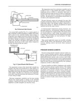
1993; Johnson 1990). These layers
of
protection start with
the
basic
process
design
and
include control systems, alarms
and
interlocks, safety
shutdown
systems, protective systems
and
response plans
as
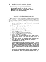
illustrated
in
Figure
2-1.
Inherent
and
passive approaches
to
safety
can be a
part
of
several
layers
of
protection.
For
example, proper dike design
can
minimize
the
evap-
oration
of a
spilled material. However,
a
truly inherent safety approach will
be
directed
at the
innermost layer
of
protection—the
process
design.
The
best
first
line
of
defense
is to
design
a
process
in
which hazardous incidents cannot
happen.
If
such
a
process
can be
designed,
or if
potential incidents
are
small
enough that they cannot hurt
anybody,
damage
the
environment
or
damage
property
if
they
do
occur, then there
will
be
no
need
for
many
of the
additional
layers
of
protection.
2.1.3
Design
Approaches
for
Inherently
Safer
Plants
Approaches
to the
design
of
inherently
safer
plants have been categorized
into
five
major
groups
by
Kletz
(1984,199Id):
•
Intensification—Using
small quantities
of
hazardous substances
•
Substitution—Replacing
a
material with
a
less hazardous substance
•.
Attenuation—Using
less
hazardous conditions
or a
less hazardous
form
of
a
material
•
Limitation
of
Effects—Designing
facilities
that minimize
the
impact
of a
release
of
hazardous material
or
energy
•
Simplification/Error
Tolerance—Designing
facilities
that make operating
errors
less likely,
and
that
are
forgiving
of
errors
that
are
made
The
remainder
of
this chapter will
discuss
strategies
for
inherently safer
plant
design
in
more detail
and
provide some specific examples, using these
categories
to
organize
the
discussions.
NOTE:
Protection layers
for a
typical process
are
shown
in
the
order
of
activation expected
as a
hazardous
condition
is
approached.
ESD
-
Emergency Shutdown
SIS
-
Safety Interlock System
Figure
2-1
Typical
layers
of
protection
in a
modern chemical
plant
(CCPS
1993).
COMMUNfTY
EMERGENCY RESPONSE
PUNT
EMERGENCY RESPONSE
PHYSICAL PROTECTION
(DIKES)
PHYSICAL PROTECTION
(RELIEF
DEVICES)
AUTOMATIC ACTION
SIS OR ESD
!
CRlTICALALARMS,
OPERATOR
SUPERVISION,
AND
MANUAL INTERVENTION
BASICCONTROLS
1
PROCESSALARMS
1
AND
OPERATOR
SUPERVISION
PROCESS
DESIGN
2.2.
INTENSIFICATION
2.2.1 Reactors
Reactors
often
represent
a
large portion
of
the
inventory
of
hazardous material
in
a
chemical
process.
A
reactor
maybe
large because
the
chemical reaction
is
slow.
However,
in
many
cases
the
chemical reaction actually occurs very
quickly,
but it
appears
to
be
slow
due to
inadequate mixing
and
contacting
of
the
reactants.
Innovative reactor
designs
that improve mixing
may
result
in
much
smaller reactors. Such designs
are
usually cheaper
to
build
and
operate,
as
well
as
being
safer
due to
smaller inventory.
In
many
cases,
improved
product quality
and
yield also result
from
better
and
more
uniform
contacting
of
reactants.
A
complete understanding
of
reaction mechanism
and
kinetics
is
essential
to the
optimal design
of a
reactor
system. With
a
thorough
understanding
of
the
reaction,
the
designer
can
identify
reactor
configurations
that
maximize yield
and
minimize size, resulting
in a
more economical
process, reducing generation
of
by-products
and
waste,
and
increasing
in-
herent
safety
by
reducing
the
reactor size
and
inventories
of all
materials.
2.2.1.1
Continuous
Stirred
Tank
Reactors
Continuous stirred tank reactors
(CSTR)
are
often
much smaller
for a
specific
production rate when compared
to a
batch reactor.
In
addition
to
reduced
inventory,
a
CSTR
usually results
in
other benefits which
can
also enhance
safety,
reduce
costs,
and
improve product quantity.
For
example:
•
Mixing
in the
smaller
CSTR
is
generally better, which
may
improve
product
uniformity
and
reduce by-product
formation
•
Greater heat transfer
surface
per
unit
of
reactor volume
can be
provided
improving temperature control
and
reducing
the
risk
of
thermal runaway
• It may be
more practical
to
build
a
small reactor
for a
high design
pressure, allowing containment
of a
runaway reaction.
In
one
reported example,
the
same quantity
of a
material
can be
manufac-
tured
either
in a
3000 gallon
(-11
m
3
)
batch reactor
or a 100
gallon
(-0.4
m
3
)
CSTR.
The
reaction
is
exothermic
and a
runaway reaction could result
in
reactor rupture.
Table
2-2
compares
the
overpressure resulting
from
reactor
rupture
at
distances
of 50 (15 m) and 100
feet
(30 m)
from
the reactor for the
two
cases,
assuming both
reactors
have
the
same design
and
rupture pressure
(Hendershot
199Ia).
To put
these numbers into perspective,
1
psig
overpres-
sure
is
sufficient
to
cause partial demolition
of
houses,
and 2-3
psig
overpres-
sure shatters
unreinforced
concrete
or
cinder block walls
(CCPS
1989).
In
considering
the relative
safety
of
batch
and
continuous processing
it is
important
to
fully
understand
any
differences
in
chemistry
and
processing
conditions, which
may
outweigh
the
benefits
of reduced
size
of a
continuous
reactor.
For
example,
Englund
(199Ia)
describes
continuous latex
processes
which have enough
unreacted
monomer
in the
continuous reactor that they
maybe
less
safe
than
a
well designed batch process.
Kletz
(199Id)
discusses
a
generic case where more severe processing conditions
may
result
in a
more
severe hazard
from
a
smaller reactor.
2.2.1.2
Tubular
Reactors
Tubular
reactors
often
offer
the
greatest potential
for
inventory reduction.
In
addition,
they
are
usually extremely simple
in
design,
containing
no
moving
parts
and a
minimum
number
of
joints
and
connections that could leak.
In
many
cases
a
relatively slow reaction
can be
completed
in a
long tubular
reactor. There
are
many devices available
for
providing mixing
in
tubular
reactors, including
jet
mixers, eductors,
and
static mixers.
Caro's acid
is an
equilibrium
mixture
of
sulfuric
acid, water
and
peroxy-
monosulfuric
acid
(HfeSOs)
that
can be
used
in the
metal extraction
and
separation industries
and
other applications where
an
extremely powerful
oxidizing
agent
is
needed.
It is
manufactured
by
reacting concentrated
sulfuric
acid
with hydrogen peroxide. Whiting
(1992)
describes
a
process
for the
manufacture
of 300
kg/day
of
Caro's
acid using
a 30
liter agitated isothermal
reactor with
a 30
minute residence time.
The
reactor must operate
at
less
than
O
0
C
to
avoid product decomposition.
An
improved process uses
an
adiabatic
tubular
reactor with
a
volume
of 20
milliliters
and a
residence time
of
less
than
1
second
to
produce 1000 kg/day
of
Caro's
acid,
a
reactor size reduction
of
1500:1.
The
process requires
an
elevated temperature,
but the
short residence
time,
and
immediate reaction
of the
product with
the
solution
to be
treated,
minimize
decomposition
at the
elevated temperature.
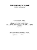
A
batch process
for the
manufacture
of a
nonhazardous
product
from
several hazardous
raw
materials
is
shown
in
Figure 2-2.
The
batch stirred tank
reactor
has a
volume
of
several thousand gallons.
A new
process,
as
shown
in
Figure
2-3,
was
developed using
a
tubular reactor containing static mixing
Table
2-2
Effect
of
Size
on
Overpressure
Due to
Vessel
Rupture
8
Distance
(feet)
50
100
a
Henderehot!991a
Overpressure
from
Vessel
Rupture
(psig)
3000
Gallon
Batch Reactor
3.4
1.1
1
0O
Gallon
Continuous
Reactor
0.62
0.27
elements
to
replace
the
batch
process.
The new
reactor
was so
much smaller
that
when
a
group
of
people
who had
seen
the
original plant toured
the new
manufacturing
facility,
they looked
for a
large reactor
and
finally
mistook
the
final
product storage tank
for the
reactor. Paul
(1988)
emphasizes
the
impor-
tance
of a
thorough study
of the
chemical reaction mechanisms
and
kinetics
in
several examples
from
the
pharmaceutical
industry,
allowing
the
process
designers
to
identify
optimal reactor configurations using novel designs
including
tubular reactors with static mixing elements.
2.2.1.3
Gas-Liquid Reactions
Mass
transfer
is
often
the
rate limiting step
in
gas-liquid
reactions,
and
novel
reactor designs that increase mass
transfer
can
reduce reactor size
and
also
improve
process
yields.
As an
example (Koestler 1992),
an
organic material
was
originally chlorinated
in a
glass-lined batch stirred tank
reactor,
with
chlorine
fed
through
a dip
pipe. Replacement
of the
stirred tank reactor with
a
loop reactor, with chlorine
fed to the
recirculating
liquid stream through
an
eductor,
reduced reactor size, increased productivity
and
reduced chlorine
usage
as
summarized
in
Table
2-3.
RAW
MATERIALS
RAW
MATERIALS
STATIC
MIXER
REACTOR
(SEVERAL
THOUSAND
GALLONS)
STORAGE TANK
(SEVERAL
THOUSAND
GALLONS)
Figure 2-2.
A
large batch reactor
to
manufacture
a
product
Figure 2-3.
A
tubular
reactor
to
manufac-
ture
the
product
of
Figure
2-2.
Table
2-3
Effect
of
Reactor Design
on
Size
and
Productivity
for a
Gas-Liquid
Reaction
8
Reactor
Type
Reactor
Size
(liters)
Chlorination
Time
(hr)
Productivity
(kg/hr)
Chlorine
Usage
(kg/
100
kg
product)
Caustic
Usage
in
Vent
Scrubber
a
Koestler!992
Batch
Stirred
Tank
Reactor
8000
16
370
33
31
Loop
Reactor
2500
4
530
22
5
2.2.1A
Some Additional
Examples
of
Intensification
Nitroglycerine
formerly
was
manufactured
in
batch reactors containing more
than
one ton of
material. Newer
CSTR
processes
significantly reduce
the
inventory,
and the
Nobel
AB
process uses
a
mixing
eductor
reactor
to
reduce
inventory
to
about
1 kg
(Dale
1987,
Kletz
1984,199Id).
Some ethylene oxide
derivatives
can be
manufactured
in a
continuous tubular reactor rather than
a
batch reactor containing
a
potentially
flammable
vapor space (Kletz
199Id).
Adipic
acid
can be
manufactured
in an
internally cooled plug
flow
reactor
rather than
an
externally cooled
CSTR
(Kletz 1984). Kletz
(1984,199Id)
pro-
vides additional examples
of
intensification
through improved reactor design.
2.2.2
Storage
and
Material
Transfer
Raw
material
and
in-process storage tanks
often
represent
a
major
portion
of
the
risk of a
chemical plant. Hazardous material transfer lines
can
also
be a
significant
hazard. Attention
to the
design
of
storage
and
transfer equipment
can
reduce hazardous material inventory.
2.2.2.1
Storage
Storage
tanks
for raw
material
and
intermediates
are
often
much larger than
really
necessary, usually because this makes
it
"easier"
to
operate
the
plant.
The
operating
staff
can pay
less attention
to
ordering
raw
materials
on
time,
or can
accept downtime
in a
downstream processing unit, because upstream
production
can be
kept
in
storage until
the
downstream unit
is
back
on
line.
This
convenience
in
operation
can
come
at a
significant
cost
in risk of
loss
of
containment
of the
hazardous materials being stored.
The
process design
engineers must question
the
need
for all
intermediate hazardous material
storage,
and
minimize quantities where such storage
is
really needed. Similar-
Iy,
hazardous
raw
material storage should also
be
minimized,
with
greater
attention
being
given
to
"just
in
time" supply. Inventory reduction
can
also
result
in
lower inventory
costs,
as
well
as
increasing
the
inherent safety
of the
manufacturing
facility.
The
reduction
in
inventory resulting
from
greater attention
to
plant
opera-
tions
and
design
of
unit interactions
can
be
extremely large. Wade
(1987)
gives
several excellent examples:
• An
acrylonitrile plant eliminated 500,000 pounds
(-277,000
kg) of in-
process storage
of
hydrogen cyanide
by
accepting
a
shutdown
of the
entire unit when
the
product purification area shut down. This applied
pressure
to the
plant
to
solve
the
problems that caused shutdown
of the
purification
area.
•
Another acrylonitrile plant supplied by-product hydrogen cyanide
to
various other units.
An
inventory
of
350,000 pounds
(-159,000
kg) of
hydrogen cyanide
was
eliminated
by
having
the
other units draw directly
from
the
acrylonitrile plant. This required considerable work
to
resolve
many
issues related
to
acrylonitrile purity
and
unit scheduling.
• A
central bulk chlorine system with large storage tanks
and
extensive
piping
was
replaced with
a
number
of
small cylinder
facilities
local
to the
individual
chlorine
users.
Total inventory
of
chlorine
was
reduced
by
over 100,000
pounds
(~45,360
kg).
2.2.2.2Transfer
Piping
Inventory
in
transfer lines
can be a
major
factor
in
overall
facility
risk. For
example,
a
quantitative
risk
analysis
of a
chlorine storage
and
supply system
identified
the
pipeline
from
the
storage area
to the
manufacturing
area
as the
most
important contributor
to
total
risk
(Hendershot
199Ib).
To
minimize
the
risk
associated with
transfer
lines, their length should
be
minimized
by
careful
attention
to
unit location
and
pipe routing. Pipe size should
be
sufficient
to
convey
the
required amount
of
material
and no
larger. However,
it is
impor-
tant
to
remember that small bore piping
is
less robust
and
less tolerant
of
abuse
when compared
to
large
piping,
and
that additional attention
to
proper
support
and
installation will
be
required
(IChemE
1987).
In
some
cases,
for
example,
chlorine
for
water treatment applications,
it may be
possible
to
transfer
material
as a gas
rather than
a
liquid with
a
large reduction
of
inventory
in the
transfer line.
Options
to
reduce
the
inventory
in a
pipeline will reduce
the
downwind
distance
to a
particular concentration
of
concern
of a
toxic
or flammable
material.
For
example, Table
2-4
compares
the
downwind distance
to
a
25
ppm
chlorine concentration
as a
result
of the
rupture
of
various size liquid
and
vapor chlorine
pipes.
2.2.3 Distillation
Some
suggestions
for
inventory reduction
in
conventional distillation systems
include:
•
Minimize
the
size
of
reflux
accumulators
and
reboilers
(Dale 1987).
• Use
internal
reflux
condensers
and
reboilers where practical (Dale 1987).
• Use
column internals that minimize holdup without
sacrificing
operation
efficiency
pale
1987).
•
Reduce
the
amount
of
material
in the
base
of the
column
by
reducing
the
diameter
of the
base
(Kletz
199Id).
•
Remove
toxic,
corrosive,
or
otherwise hazardous materials early
in a
distillation sequence, reducing
the
spread
of
such materials throughout
a
process
(Wells
and
Rose
1986)
Low-inventory distillation equipment, such
as the
thin
film
evaporator,
is
also available
and
should
be
considered
for
hazardous materials. This equip-
ment
offers
the
additional advantage
of
short residence time
and is
particular-
ly
useful
for
reactive
or
unstable materials.
The
use of
Higee rotating distillation equipment, invented
by
Imperial
Chemical
Industries
(ICI),
can
reduce inventory
by a
factor
of
1000.
The
distillation occurs
in a
rapidly rotating
bed
containing
a
packing with
a
high
specific
surface area. Vapor
is fed to the
outside
and
moves
to the
center,
contacting liquid
fed at the
center
and
moving outward. Extremely
effective
separations
are
possible
with
a
small in-process inventory
and
very
short
residence time. This technology
is
described
in
more detail
by
Kletz
(199Id).
Table
2-4
Effect
of
Various Options
to
Reduce Inventory
on the
Hazard Zone
Resulting from
the
Rupture
of a
500-Foot Chlorine Transfer Pipea
Pipe
Diameter
(in)
2
1
1
Chlorine
State
Liquid
Liquid
Vapor
Inventory
(kg)
430
110
2
Downwind
Distance
to
Atmospheric
Chlorine
Concentration
of
25 ppm (m)
2400
1700
650
a
Henderehot
1991a
a
2.2.4
Heat
Transfer
Heat
transfer
equipment
has a
great variation
in
heat transfer area
per
unit
of
material
volume. Table
2-5
compares
the
surface
compactness
of a
variety
of
heat exchanger types.
Process
inventory
can be
minimized
by
using heat
exchangers with
the
minimum volume
of
hazardous
process
fluid
for the
heat
transfer
area required.
2,3
SUBSTITUTION
2.3.1
Chemistry
Inherent
safety
of the
manufacturing
process
for a
material
can be
greatly
increased
by
development
of
alternate chemistry using less hazardous
raw
material
or
intermediates,
reducing inventories
of
hazardous
materials,
or
operating
at
less severe processing conditions.
Identification
of
catalysts
to
enhance reaction selectivity
or
allow desired reactions
to be
carried
out at a
lower temperature
or
pressure
is
often
a key to
development
of
inherently
safer
chemical synthesis routes.
The
following
are
some specific examples
of
innovations
in
process chemistry that result
in
inherently
safer
processes.
Halogenated polymers
can be
manufactured
by
conducting
the
polym-
erization step
first,
followed
by
halogenation
of the
polymer. This avoids
Table
2-5
Surface
Compactness
of
Heat
Exchangers
8
Type
of
Exchanger
Shell
and
tube
Plate
Spiral
plate
Shell
&
finned
tube
Plate
fin
Printed circuit
Regenerative-rotary
Regenerative-fixed
Twin
screw extruder
Human
lung
Surface
Compactness
(rr^/m
3
)
70-500
120-225
up to
1,000
Up
to 185
65-270
up to
3,300
150-450
up to
5,900
1,000-5,000
Up
to
6,600
Up
to
15,000*
"High"
20,000
*
Kletz
1991
d
Some types have
a
compactness
as low as 25m
/m
.
Halogenated polymers
can be
manufactured
by
conducting
the
polym-
erization step
first,
followed
by
halogenation
of the
polymer. This avoids
manufacture
and
handling
of
hazardous
halogenated
monomers
(Burch
1986;
Kharbanda
and
Stallworthy
1988).
The
insecticide
carbaryl,
the
product manufactured
at
Bhopal,
can be
produced
by
several
routes,
some
of
which
do not use
methyl
isocyanate,
the
material
that
was
released
in the
Bhopal accident,
or
that generate only small
quantities
of
methyl isocyanate
as an
in-process intermediate
(Kletz
199Id).
DuPont
has
developed
a
proprietary
process
for
manufacture
of
carbamate
insecticides which generates
and
immediately consumes methyl isocyanate.
Total
methyl isocyanate inventory
in the
process
is no
more than
10
kilograms
(Kharbanda
and
Stallworthy 1988).
Acrylonitrile
can be
manufactured
by
reacting acetylene with hydrogen
cyanide:
CHSCH
+
HCN
-4
CH
2
=CHCN
A
newer ammoxidation process uses less hazardous
raw
materials
(propyl-
ene and
ammonia) (Dale 1987;
Puranik
et
al.
1990):
CH
2
=CHCH
3
=
NH
3
+
|o
2
-*
CH
2
=CHCN
+
3H
2
O
2t
The
Reppe process
for
manufacture
of
acrylic
esters
uses
hazardous
raw
materials,
acetylene
and
carbon monoxide,
and a
catalyst with high acute
toxicity,
nickel
carbonyl,
to
react with
an
alcohol
to
make
the
corresponding
acrylic
ester
CH^CH
+
CO = ROH
Uj^l?*
4
CH
2
=CHCO
2
R
rid
The
newer
propylene
oxidation process
uses
less
hazardous materials
to
first
manufacture
acrylic acid followed
by
esterification
with
the
appropriate
alcohol
(Hochheiser
1986).
CH
2
=CHCH
3
+
|o
2
cataI
H
st
>
CH
2
CHCO
2
+
H
2
O
TJ+
CH
2
CHCO
2
H
+
ROH
-
£L
-»
CH
2
=CHCO
2
R
+
H
2
O
Polymer supported reagents, catalysts, protecting groups
and
mediators
can
be
used
in
place
of the
corresponding small molecule materials (Sher-
rington
1991).
The
reactive species
is
tightly bound
to a
macromolecular
support which immobilizes
it.
This generally makes toxic, noxious
or
cor-
rosive material much
safer.
The use of
polystyrene sulfonic acid catalyst
for
CH
3
OH
+
CH
2
=C(CHO
2
Pd
^
rem
Sul
f
mic
Ad
4
CH
3
OC(CHs)
3
Sherrington
(1991) provides several additional examples
and
suggestions
for
future
development.
Chemistry
of
side reactions
and
by-products
may
also
offer
opportunities
for
increasing
the
inherent
safety
of a
process.
For
example,
a
process
involv-
ing a
caustic hydrolysis step uses ethylene
dichloride
as a
solvent. Under
the
reaction conditions
a
side reaction between sodium hydroxide
and
ethylene
dichloride produces small
but
hazardous quantities
of
vinyl chloride:
C
2
H
4
Cl
2
+
NaOH
-»
C
2
H
3
Cl
+
NaCl
=
H
2
O
An
alternative
nonreactive
solvent
has
been
identified
which eliminates
the
hazard
(Hendershot
1987).
Phase transfer catalysis ("Phase Transfer" 1990;
Starks
1987;
Starks
and
Liotta
1978) processes
for the
synthesis
of
many organic materials
use
less,
or
sometimes
no,
organic solvents,
may use
less toxic
solvent,
may
allow
use of
less hazardous
raw
materials
(for
example,
aqueous
HCl
instead
of
anhydrous
HCl),
and
operate
at
milder conditions. Some types
of
reactions where phase
transfer
catalysis
has
been applied include:
•
esterification
•
nucleophilic
aromatic substitution
•
etherification
•
dehydrohalogenation
•
oxidations
•
alkylation
•
aldol
condensations
Rogers
and
Hallam
(1991) provide
a
number
of
additional examples
of
chemical approaches
to
inherent
safety,
involving synthesis routes, reagents,
catalysts
and
solvents.
2.3.2 Solvents
Replacement
of
volatile organic solvents with aqueous systems
or
less
haz-
ardous organic materials improves
safety
of
many processing operations
and
final
products. Some examples include:
•
Water based paints
and
adhesives
in
place
of
solvent based products
•
Aqueous
or dry
flowable
formulations
for
agricultural chemicals instead
of
organic solvent formulations
•
British computer manufacturer
ICL has
eliminated
chlorofluorocarbons
from
its
manufacturing
processes,
replacing them with aqueous cleaning
systems
for
flux
removal
("Technology"
1991).
In the
United States,
IBM
Table
2-6
Some Examples
of
Solvent
Substitutions
3
Chloroform
-+
Acetone
—*
Ethyl Acetate
-*
Ethanol
Dichloromethane
-4
Ethanol
Trichloroethylene
-*
Aqueous
System
Acetic Acid
-4
Aqueous
System
Propanol
-*
1,2-Propanediol
—>
Aqueous
System
a
Adapted
from
Goldschmidt
and
Filskov
1990
has
reduced
or
eliminated
chlorofluorocarbons,
chloroform,
methylene
chloride,
and
other hazardous
solvents,
replacing them with nonhazar-
dous materials (Kelley
1992).
Apple Computer reports
the
elimination
of
all
chlorofluorocarbons
for
cleaning electronic assemblies
and has
con-
verted
to
water based
processes
(Chemical
WeekNewswire
1992).
• The
United States
Air
Force
is
evaluating
a
process
called
Coldjet
which
removes paint
from
airplanes using
a jet of
frozen
carbon dioxide pellets
in
place
of
hazardous paint removal solvents (Welter
1991).
•
Consumer paint removal products based
on
less
volatile organic
esters
are now
available
as
substitutes
for
products
based
on
hazardous solvents
such
as
methanol, toluene, acetone
and
methylene chloride ("Paint
Re-
movers" 1991).
• A
Danish survey (Goldschmidt
and
Filskov
1990)
confirms
the
feasibility
of
solvent substitution
as a way of
reducing workplace exposure
to
hazardous materials, particularly organic
degreasing
solvents. Table
2-6
lists some
of the
substitutions
identified
by
this industrial survey.
2.3.3 Utility Systems
Utility
and
plant services systems must also
be
examined
for
options
to
increase
the
inherent safety
of a
plant
or
process.
For
example:
• Use
water
or
steam
as a
heat transfer medium rather than
flammable
or
combustible oils
(Kharbanda
and
Stallworthy
1988;
Kletz
199Id).
• Use
high
flash
point oils
or
molten salt
if
water
or
steam
is not
feasible
(Dale
1987; Kletz
199Id).
•
Chlorofluorocarbon
refrigerants
have
been cited
as
inherently
safer
alter-
natives
to
refrigerants such
as
ammonia
and
propane. Many chloro-
fluorocarbons
are now
being phased
out
because
of
suspected adverse
environmental impact. This creates
new
challenges
for
industry
in
iden-
tifying
new
refrigerants that have
the low
acute
toxicity
and
fire
hazards
of
chlorofluorocarbons
but
that
do not
have long term adverse environ-
mental
impacts.
•
Alternatives
to
chlorine
are
available
for
water treatment
and
disinfection
applications.
For
example,
sodium
hypochlorite
has
been used both
in
industrial
and
municipal water treatment applications
(Governale
1989;
Somerville
1990),
and
calcium hypochlorite
is
another
possible
alterna-
tive.
• Use
magnesium hydroxide slurry
to
control
pH,
rather than concentrated
sodium
hydroxide
(Englund
199Ia).
2.4
ATTENUATION
Attenuation
means using materials under less hazardous conditions. This
can
be
accomplished
by
strategies that
are
either physical
(e.g.,
lower tempera-
tures,
dilution)
or
chemical
(e.g.,
development
of a
reaction chemistry that
operates
at
less severe
conditions).
2.4.1 Dilution
Dilution
reduces
the
intrinsic hazards associated with storage
of a
low-boiling
hazardous material
in two
ways:
by
reducing
the
storage
pressure
and by
reducing
the
initial
atmospheric concentration
in the
event
of a
release.
Materials
that
boil below normal ambient temperature have
often
been stored
in
pressurized systems under their ambient temperature vapor
pressure.
The
pressure
in
such
a
storage system
can
be
lowered
by
diluting
the
material with
a
higher boiling solvent. This reduces
the
driving
force
(the
pressure
difference
between
the
storage system
and the
outside environment)
in
case
of a
leak
in
the
system, reducing
the
rate
of
release.
As an
example, Table
2-7
shows
the
effect
of
water dilution
on the
vapor pressure
of
ammonia
and of
mono-
methylamine
solutions. Handling
of
these materials
as a
sufficiently
dilute
aqueous solution allows them
to
be
stored
at
atmospheric pressure rather than
in
a
pressurized
system.
A
distinct
benefit
of
storage
in the
diluted
form
is the
reduced partial
pressure
of the
hazardous component
in the
solution.
In the
event
of a
loss
of
containment
accident,
the
atmospheric concentration
of the
hazardous mate-
rial
at
the
spill location will
be
reduced.
The
reduced atmospheric concentra-
tion
at the
source results
in a
smaller hazard zone downwind
of the
spill.
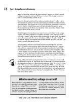
The
effect
of
water dilution
of
monomethylamine,
a
flammable
and
toxic
material,
on the
vapor cloud
resulting
from
a
loss
of
containment incident
is
shown
in
Figure
2-4.
Monomethylamine boils
at
-6.7
0
C
and has a
vapor
pressure
of
about
50
psig
at
25
0
C.
Figure
2-4
shows
the relative
hazard
zones,
defined
as the
distance
from
the
source within which
the
monomethylamine
vapor
concentration will exceed
a
specified value.
The
loss
of
containment
event
in
this example
is the
complete
failure
of a
1-inch
liquid pipe under
a
specific
atmospheric condition
for (A)
anhydrous monomethylamine
and (B)
a 40%
aqueous monomethylamine solution.
The
hazard zone extends
to a
much
greater distance
in the
case
of
ambient storage
of
anhydrous
mono-
methylamine.
Many materials
can be
handled
in a
dilute
form
to reduce the risk of
handling
and
storage.
Some other examples include:
•
muriatic acid
in
place
of
anhydrous
HCl
•
dilute nitric acid
in
place
of
concentrated
fuming
nitric acid
•
sulfuric
acid
in
place
of
oleum
(SOs
solution
in
sulfuric
acid)
for
sulfona-
tion reactions
If
a
chemical
process
requires the
concentrated
form
of a
material,
it may
be
feasible
to
store
it as a
more dilute
form
and
concentrate
the
material,
by
distillation
or
some other technique
in the
plant
prior
to
introduction
to the
process.
This
reduces the
inventory
of
material with greater intrinsic hazard
to the
minimum
amount
required to
operate
the
process.
Table
2-7
Vapor Pressure
of
Aqueous Ammonia
and
Monomethylamine
Solutions
8
Ammonia
(21
0
C)
Concentration
(Wt
%)
100.0
48.6
33.7
28.8
19.1
Vapor Pressure
(atm)
8.80
3.00
1.10
0.75
0.31
Monomethylamine
(2O
0
C)
Concentration
(Wt.
%)
100.0
50.0
40.0
Vapor
Pressure
(atm)
2.80
0.62
0.37
a
Henderehot
1991a