Tài liệu 2D Artwork and 3D Modeling for Game Artists- P2 docx
Bạn đang xem bản rút gọn của tài liệu. Xem và tải ngay bản đầy đủ của tài liệu tại đây (3.52 MB, 50 trang )
The Final Objective
Having the two object models in mind, I want you to pause a minute and think
about why I chose them. The RF-9 plasma gun is a great start. Although it’s no ordi-
nary object, it’s not too difficult to model, and for now will have no moving parts.
This is my favorite type of object to model and texture, because it’s generally quick
to develop and has what I would consider an easy texture skin. Beveled, futuristic
metal is fun and looks really cool, so I think you’ll enjoy it—in fact, that will be
your first modeling project to get your feet wet.
The slogre model, on the other hand, will be by far the most complex. The slogre
will consist of only one skin mesh, but will have an internal skeletal structure
(known in 3D Studio Max as a biped object) that will be used to drive the mesh defor-
mation. That is, as the bones in the biped object move around, the vertices in the
mesh will follow. On top of that, you’ll be weighting the mesh (adjusting the behav-
ior of the mesh around the bones) and skinning. Lastly, dummy nodes must be
placed all over the slogre to signify locations for the character to mount weapons,
backpacks, point-of-view cameras, and the like. The model itself, being organic, will
also be the most time consuming, so we’ll save that for last.
Summary
Developing a complex 3D game model is definitely a time-consuming process that
must be well-planned in order for your model to be successful and presentable in a
gaming environment. The development can be broken down into several basic
steps, beginning with an initial concept sketch to provoke modeling ideas (which
leads to creating the model itself in a 3D modeling program), followed by U-V
mapping, texturing, possibly applying a bones system to deform the mesh, and
finally outputting to a game engine of choice.
Lars provided some great sketches that you can use as you create the models and
textures for this game. Of course, you don’t have to stick like glues to the sketches
(although it should be close); feel free, by all means, to make up your own models
as you go. The techniques I’ll show you—from modeling, to U-Ving, to skinning
and animation—will still apply.
The next step in the development process is creating the actual object meshes, and
in this part of the book, I’ve broken down the creation of the plasma gun and slogre
mesh objects into their own chapters (Chapters 3 and 4, respectively). Using the
modeling techniques I will describe, you should be able to make just about anything!
24
2.
Getting Ready to Model: Concept Art
TEAMFLY
Team-Fly
®
Please purchase PDF Split-Merge on www.verypdf.com to remove this watermark.
CHAPTER 3
Modeling
the RF-9
Plasma Gun
with
trueSpace 9
Please purchase PDF Split-Merge on www.verypdf.com to remove this watermark.
I
n the previous chapter, where I introduced you to the logical structure of creat-
ing game assets, I envisioned and generated (with the help of my sketch art col-
league, Lars) a draft of a cool weapon that I’ll now show you how to create in 3D.
In this chapter you will
■
Set up the trueSpace 6 environment in preparation for game modeling.
■
Logically plan out the modeling attributes for the RF-9 plasma gun.
■
Build the RF-9 step-by-step using primitives and point-editing techniques.
■
Optimize the RF-9 mesh and check for errors.
■
Export the model.
An Overview
You’ve fleshed out the concept for the RF-9 plasma gun and generated some
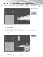
detailed sketches. The next step is mesh creation, as indicated by the workflow
depicted in Figure 3.1.
To give you a quick review, Figure 3.2 shows the RF-9 plasma gun sketch that you’ll
be using to model the plasma gun; you probably remember from Chapter 2,
“Getting Ready to Model: Concept Art,” that this sketch was generated by me and
my colleague Lars Ricaldi.
26
3.
Modeling the RF-9 Plasma Gun with trueSpace 6
Figure 3.1
The next step in
compound-asset
development: mesh
creation.
Please purchase PDF Split-Merge on www.verypdf.com to remove this watermark.
When you’re finished,
you should end up with
something like the mesh
shown in Figure 3.3.
27
An Overview
Figure 3.2
The RF-9 you’ll be
modeling in this
chapter
(sketch
courtesy Lars
Ricaldi).
Figure 3.3
The completed
plasma-gun mesh.
NOTE
The sections that follow explain how to modify the
trueSpace 6 environment for modeling, as well as
other items you should consider before you begin.
If you’re already familiar with trueSpace and want
to jump right into the modeling, go ahead and skip
to the section titled “Modeling the RF-9.”
Please purchase PDF Split-Merge on www.verypdf.com to remove this watermark.
Setting Up the
trueSpace 6 Environment
In case you have not yet installed any version of trueSpace on your computer, I’ve
provided a demo of trueSpace 6 on the CD-ROM that accompanies this book.
Install it as you would any other program, and then copy the file G-LoK.tsc
(as well as truespace.key and keylist.txt if you want to adhere to my keyboard short-
cuts) from the CD-ROM to the \trueSpace6\ folder of your program’s installation
directory.
After the G-LoK.tsc file is copied, it’s
time to load this custom modeling
configuration. To do so, click on the
Configuration Library button, right-
click in the library’s blank space,
and choose Import. Then browse to
G-LoK.tsc file and click OK. You
should end up with a configuration
that looks like the one shown in
Figure 3.4. G-LoK, by the way, is my
game artist ‘handle’, so if you ever
see art with my “GLK” logo, you
know it’s yours truly.
The next few sections explain other settings that help with your modeling
environment.
Changing the World
and Object Units
Generally speaking, one meter in the trueSpace modeling environment equals one
meter in the world of the video game you’re creating. (It’s a good idea to use the
metric system because most game engines are based on it.) To ensure that your
modeling environment is set to use the metric system, do the following:
1. Right-click the Object button (with the white arrow) to open the Object Info
panel (see Figure 3.5).
28
3.
Modeling the RF-9 Plasma Gun with trueSpace 6
NOTE
G-LoK.tsc is an interface-configuration
file that will set up your modeling envi-
ronment my way, displaying three
orthogonal views (Left, Front, and Top)
as well as a background Perspective
view. Over the years I’ve found that this
is a fairly optimal way to model, but by
all means, you should arrange the envi-
ronment to your liking.
Please purchase PDF Split-Merge on www.verypdf.com to remove this watermark.
29
Setting Up the trueSpace 6 Environment
Figure 3.4
Changing the model-
ing-interface configu-
ration by importing
the G-LoK.tsc file.
Configuration
Library button
Figure 3.5 Setting
the modeling units in
the Object Info panel.
The Object button
Please purchase PDF Split-Merge on www.verypdf.com to remove this watermark.
2. Click the red triangle in the
upper-right corner of Object Info
panel to expand it.
3. Set the World field to Meters.
4. Set the Object field to Meters.
Setting the Dynamic
Rendering Mode
trueSpace (and most other modeling programs) allows you to apply various settings
to the video mode of your modeling environment, such as wireframe, solid, trans-
parent, and so on. I find it easiest to create mesh objects in Transparent Wireframe
mode, which means your models are see-through, and that both the edges and
vertices of the model are displayed at the same time. To switch to this mode, do the
following:
1. Click on the Display Options button in the bottom-right portion of the
screen (see Figure 3.6).
30
3.
Modeling the RF-9 Plasma Gun with trueSpace 6
TIP
Rather than closing the Object Info
panel, it’s a good idea to move it
over to the corner of the screen;
that way, you can reference your
polygon count as you model.
Figure 3.6 Setting
the dynamic render-
ing modes.
The Display Options:
DirectX button
The Draw Objects as
Transparent Outline button
Please purchase PDF Split-Merge on www.verypdf.com to remove this watermark.
2. Select either DirectX or OpenGL mode.
(One mode might outperform the other
depending on your video card, so check
your video-card manufacturer’s docu-
mentation for more information.)
3. Select the Draw Objects tool, and press
and hold down your mouse button.
Then, choose the Draw Objects as
Transparent Outline button.
Texture Resolution
If you apply bitmaps to any object in your dynamically rendered world, you’ll need
to crank up the dynamic texture resolution—otherwise, your textures will appear
pixelated. Do this by right-clicking the Draw Objects tool (or by clicking File,
Display Options), and setting the Txt Res option to 512×512.
Keeping the Point Edit Tools Handy
Much of the modeling you’ll be doing is based on point editing—that is, building
or modifying your objects at the vertex (point) and face level. I like to keep the
Point Edit tools right next to the Eye Rotate
and Eye Move tools, at the middle-right of
the screen, to make them easily accessible.
To make a copy of these tools, press and
hold the Ctrl key as you drag the Point Edit
tools to the desired area (see Figure 3.7). If
you click once on the tool’s anchor bar (just
to its left), it will expand the tool list and
anchor it to that area.
Modeling Considerations
If you saw the movie Final Fantasy, you were probably struck by the incredible detail
of the characters, weapons, environments, and so on. That photorealistic detail was
the product of the extraordinarily high polygon meshes used to make the models
used in the film; indeed, a typical character model’s face alone had well over
31
Modeling Considerations
NOTE
The rendering options described
here will apply only to the active
window.To activate a window, left-
click on it.
NOTE
The Point Edit tools will be visi-
ble only when an object is pre-
sent and you’re in Point Edit
mode (obtained simply by right-
clicking on a mesh object).
Please purchase PDF Split-Merge on www.verypdf.com to remove this watermark.
50,000 polygons. Sadly, however, if you were to use such high polygon meshes for
your game, the player’s computer would come to a screeching halt trying to render
all of the detail. In fact, what you saw in Final Fantasy was the result of countless
hours of post-production rendering on very powerful computers (most likely in a
rendering array, with dozens of computers linked together, sharing the rendering
process).
Models for games are different from models for production, such as cover art, tele-
vision, and movies. That’s because games have dynamic rendering environments;
that is, as a player moves around in 3D space, all 3D mesh objects are rendered to
screen at least 30 times per second. That means the player’s computer’s CPU and
graphics processors must constantly transform the game world and render it at the
same time—which in turn limits the number of polygons your models may con-
tain. Models with high levels of polygonal detail may look better, but will be so slow
to render on a player’s computer as to make them unusable.
Put simply, models for games must be created to accommodate the average
computing power of home computers on the market. These days, that equates
to designing your models to work with computers in the Pentium IV and V range,
at about 2.5 to 3.0 GHz. That means rather than creating character models with
50,000–100,000 polygons, as seen in the film Final Fantasy, you’ll need to create
32
3.
Modeling the RF-9 Plasma Gun with trueSpace 6
Figure 3.7
Locating and
anchoring the Point
Edit tools.
The Point
Edit button
Please purchase PDF Split-Merge on www.verypdf.com to remove this watermark.
character models with polygons in the
neighborhood of 2,000 to 5,000, and
weapons possessing only 500–2,000 poly-
gons. This need for a low polygon
(poly) count will deeply affect the way
you model; with every step you take to
shape your object, you’ll work to mini-
mize the count.
In addition to considering poly count,
you’ll also want to think about texture
mapping as you model. By making nice
seams in your models in hidden areas,
you’ll make the process of unwrapping
the U-V texture coordinates much eas-
ier. For details on unwrapping U-Vs, see
Part II, “Unwrapping U-Vs with DeepUV.”
Modeling the RF-9
Creating a model of the RF-9 plasma gun will be quick and fairly simple; for overall
good looks, you’ll rely more on texturing the weapon than creating a highly
detailed mesh. Modeling the RF-9 is, in this case, essentially a seven-step process:
1. Plan the model’s dimensions and poly count, and build reference plane.
2. Build the muzzle.
3. Build the barrel.
4. Build the grip.
5. Build the hoops and hose.
6. Optimize and triangulate.
7. Export the model for texturing.
In the sections that follow, I’ll show you how to use trueSpace, which features one
of the best modeling interfaces on Earth, to model the RF-9 plasma gun using the
steps outlined here. Of course, you can use any modeling program you wish,
including 3D Studio Max (a demo of which is included on the CD-ROM); the mod-
eling techniques I’ll show you can be ported to other programs. It’s up to you to
know how those programs and their tools work, however.
33
Modeling the RF-9
TIP
One way to avoid high poly counts is to
apply textures to low-poly-count models
for a similar effect. For instance, the
RF-9 has a hose-like item running the
length of the action, but modeling a
hose would require hundreds of poly-
gons. Instead, you can use a simple
curved cylinder, and later apply a tex-
ture map that features an image of the
bumps in a hose to that area. If you can
fake something with a 2D map, then it
might not be necessary to have high
poly counts for certain areas.
Please purchase PDF Split-Merge on www.verypdf.com to remove this watermark.
Step 1: Planning the Model’s
Dimensions and Poly Count,
and Creating a Reference Plane
Before you start dropping objects all over your scene, it’s a good idea to plan your
model and set up your environment so that you can avoid the most frustrating mis-
take that modelers make all the time: getting halfway finished with your model and
having to scrap it all or backtrack because you didn’t plan ahead. Following are a
few things to consider.
The RF-9: Pea Shooter or @$$-Kicker?
I mentioned in Chapter 2 that the slogre stands at about four meters (13 feet) tall.
Given that the slogre is more than twice the size of an average human male, the
RF-9 can be big and heavy, despite the fact that, as illustrated in the sketches you
saw in Chapter 2, the slogre carries it in one hand. I figure a beast that possesses
the size and strength of a slogre can handle a weapon that’s roughly two meters in
length—half of his height—with the height from the gun’s strap hoop to the bot-
tom of the handle being about one meter (refer to Figure 3.2). Knowing the
dimensions of the weapon will sure come in handy as you proceed with creating
the model!
Target Polygon Count
Until your computer hardware lets you make objects suitable for The Matrix, you’ll
have to devise a target polygon count for your model. To give you a framework to
34
3.
Modeling the RF-9 Plasma Gun with trueSpace 6
NOTE
In the event you need a primer on using trueSpace, I’ve included
on this book’s CD-ROM a tutorial covering trueSpace 4.
I focused the tutorial on trueSpace 4, rather than trueSpace 6,
because version 4 is clean and considerably less complicated
than version 6, but uses the same basic modeling environment.
Once you have a handle on using version 4, it’s less likely you’ll
be confused and overwhelmed by the plethora of advanced
modeling tools in version 6.
TEAMFLY
Team-Fly
®
Please purchase PDF Split-Merge on www.verypdf.com to remove this watermark.
work from, 3D FPS games from the
late 1990s had weapons that hovered
around 300 polygons, while more
recent games feature weapons in the
700-polygon range. Keeping with this
linear growth, you can safely target
your weapon’s poly count to be
around 1000. That’s pretty good
detail, allowing you to include more
3D and less texture. Of course, with
good texturing, an expert modeler can
keep the poly count well below that,
but for the sake of expediency, let’s
not worry about that just yet.
The Reference Plane
Unless you’re making models on-the-fly, which will happen occasionally, you’ll need
to reference a sketch or picture as you model. You can do this in one of several
ways, such as taping a hard copy to the edge of your monitor, flipping back and
forth between trueSpace and another program that houses the image, or—my
personal preference—creating a reference plane (a 2D plane you create in trueSpace
that has the actual sketch painted on it).
35
Modeling the RF-9
Levels of Detail
When you build a game, you’ll typically need several versions of the
same weapon model, each with different levels of detail (LOD). One,
which will have very high resolution, will be seen only by the player as
he holds his own weapon (because the player will be able to see the
model up close, a higher level of detail is required); one or several less-
detailed versions will feature a lower polygon count, and will be seen
being held by other players.These polygon counts may also vary with
distance. For information on creating LODs, see Part IV,“Preparing
Assets for Games with 3D Studio Max.”
NOTE
There aren’t really any rules to model-
ing; some techniques, such as point
editing, are more efficient, producing
fewer polygons. Other techniques, such
as Boolean operations with primitives
and NURBS, accelerate the process.
Of course, accelerating the modeling
process may require you to clean up
any unnecessary polygons at the end.
See Chapter 4 for details on advanced
modeling with NURBS (non-uniform
rational b-spline) objects.
Please purchase PDF Split-Merge on www.verypdf.com to remove this watermark.
To set up a reference plane, do the following:
1. Add a plane primitive to the scene (the primitives are found among the
libraries at the bottom-left of the screen). If you’re not familiar with per-
forming simple object operations in trueSpace, such as adding and manipu-
lating primitives, please review the trueSpace 4 tutorial located on this book’s
CD-ROM.
2. Right-click the Object tool (the white arrow at the bottom of the screen) to
open the Object Info screen.
3. Scale the primitive to two meters by one meter by entering the dimensions in
the Object Info screen. You’ll see a Size field in this screen; just enter these
values for X and Y (length and width, respectively).
4. Enable the Grid Snap tool. This is the icon with a blue colored grid located
at the bottom of the screen.
5. Using the Object Rotate tool (X on your keyboard), rotate the plane 90
degrees so it runs the length of the RF-9. This operation is best done in an
orthogonal view, such as Left, and right-clicking and dragging until the plane
is rotated so it stands upright in your scene.
6. Use the Move tool (Z on your keyboard) to move the plane up so the bottom
is flush with the scene’s reference grid.
7. Use the Material Editor in conjunction with the Paint Face tool to paint the
face of the plane with the image in the file RF-9 Plasma Gun.jpg, located in
the Chapter 3 Data section on the CD-ROM (see Figure 3.8).
Because the default perspective space of trueSpace is huge, you’ll need to use the
Eye Move tool to reposition your view as I have in Figure 3.8. Notice that the grid’s
units are one meter square; your plane
should be proportionate to it. (If you’re a
little confused up to this point, just load
the step1.scn file on the CD-ROM.)
36
3.
Modeling the RF-9 Plasma Gun with trueSpace 6
TIP
I’ve saved the individual modeling
steps as trueSpace .scn files in the
Chapter 3 Data section on the
CD-ROM in case you get confused.
Please purchase PDF Split-Merge on www.verypdf.com to remove this watermark.
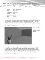
Step 2: Build the Muzzle
Now that you’ve determined the model’s dimensions and established a poly count,
it’s time to start building the model. The part of the RF-9 plasma gun that’s easiest
to model is the muzzle. Notice how the muzzle is really just a large, egg-shaped
sphere primitive with two adjoined cylinders on the top sides. This is the resonating
chamber, where the charged energy pellet enters a plasma-injection chamber and
gets superheated in a fraction of a
millisecond, before annihilating a
nearby targeted object.
37
Modeling the RF-9
Figure 3.8 Painting
the face of a properly
scaled and rotated
reference plane with
the RF-9 Plasma
Gun.jpg image.
NOTE
The modeling techniques I use for the
rest of this chapter can be applied by
anyone using trueSpace version 4.0 and
later. In the next chapter, however,
when you model the slogre and other
objects, you’ll use some of the new
tools included with trueSpace 6.
Please purchase PDF Split-Merge on www.verypdf.com to remove this watermark.
To build the muzzle, do the following:
1. Add a 12-segmented sphere primi-
tive to the scene. You can set the
segments manually by right-
clicking any of the primitives,
or you can use the Magic Ring.
(I don’t use the Magic Ring, and
have disabled it in the Preferences
dialog box.)
2. Rotate the sphere 90 degrees.
3. Using the Scale tool (C on your
keyboard), scale, elongate, and move
the sphere so it matches the one in the reference plane (see Figure 3.9).
Again, this is best done using the orthogonal views (such as Left, Front, and
Top) to help with the scaling and positioning.
4. Right-click the sphere to enter Point Edit mode.
5. Right-click the Select Using Rectangle tool and enable the Backside option.
The Backside option will allow you to make selections on your model that
include polygons nearest your point of view and those hidden behind it, or
on the model’s backside.
6. With the Select Using Rectangle tool, select the first four segments of the
sphere as shown in Figure 3.10. This selection operation is best done in an
orthogonal window; I did it in Front view.
38
3.
Modeling the RF-9 Plasma Gun with trueSpace 6
TIP
To open the basic Primitives panel,
press 6. If you use trueSpace version
5.x or higher, you can also open the
Primitives panel by clicking on the
Primitives Library button, located
in the vertical toolbar in the bot-
tom-left portion of the screen.This
contains a more extensive and help-
ful list of primitives.
Figure 3.9
Add a 12-segment
sphere primitive,
rotate it 90 degrees,
and elongate it to
match the sketch.
Please purchase PDF Split-Merge on www.verypdf.com to remove this watermark.
7. Click the Erase Vertices tool, located
within the Point Edit tools, to delete
the selection from the sphere, as shown
in Figure 3.11. (From now on, when I
want you to remove something, I’ll sim-
ply say “Select, and delete.” That’s your
cue to repeat
this step.)
8. Press Ctrl+C to make a copy of the
sliced sphere. In trueSpace 6, your cursor
will change to an arrow with a plus sign beneath it—just left-click once in
the scene to add the copy, and immediately right-click to exit the copy mode.
9. Scale and position the copy as shown in Figure 3.12; it should line up with
the reference plane’s sketch.
39
Modeling the RF-9
Figure 3.10 Use
the Select Using
Rectangle tool to
select the first four
segments of the
sphere.
Figure 3.11 Use
the Erase Vertices
tool to delete the
selection.
TIP
If you’re having trouble finding
the various tools mentioned
throughout this chapter, check
out trueSpace tutorial on the
CD-ROM that accompanies
this book.
Please purchase PDF Split-Merge on www.verypdf.com to remove this watermark.
10. Right-click the copy to enter Point Edit mode.
11. Select and delete the first two segments of the new copy, as shown in
Figure 3.13.
12. Using the Point Edit: Faces tool, select the front face of the copied sphere.
13. Use the Sweep tool to extrude the object; extend the extrusion until it’s even
with the lower sphere by dragging it to the left in an orthogonal view (see
Figure 3.14). It will help to lock the X axis for this operation to keep it
straight.
14. Use the Object Union tool to join both sphere objects together. If both
objects’ faces were aligned evenly before the union, you should get one solid
object with only one front face (see Figure 3.15).
15. Select the front face of the muzzle; you’ll extrude this to form the muzzle’s
flare (see Figure 3.16).
40
3.
Modeling the RF-9 Plasma Gun with trueSpace 6
Figure 3.12
Make a copy of
the existing sphere
object, and then
scale and position
it as shown.
Figure 3.13
Select the first two
segments of the
top sphere object
and delete them.
Figure 3.14 Sweep
the front face of the
sphere and continue
the extrusion until it
matches the face of
the lower sphere.
Please purchase PDF Split-Merge on www.verypdf.com to remove this watermark.
16. Use the Sweep tool to extrude the face of the muzzle.
17. Move and scale the extrusion in an orthogonal view so that it matches the
reference plane sketch, as shown in Figure 3.17. (Remember to use the Point
Edit: Move, Rotate, and Scale tools to do this, and not the Object Move,
Rotate, and Scale tools. These tools are located in the Point Edit tools that
pop up when in Point Edit mode.)
41
Modeling the RF-9
Figure 3.15 Use
the Object Union tool
to fuse both sphere
objects together.
Figure 3.16 Select
the front face of the
muzzle.
Figure 3.17
Sweep the front face
of the muzzle, then
move and scale the
extrusion to match
the sketch.
Please purchase PDF Split-Merge on www.verypdf.com to remove this watermark.
18. Sweep the face again, and then move, rotate, and scale the new extrusion to
match the sketch (see Figure 3.18).
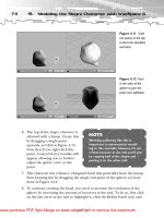
19. The top six edges of the muzzle’s end must be tapered down slightly. Use the
Point Edit: Edges tool to select them, and scale and/or move them down a
bit, as shown in Figure 3.19.
20. To hollow out the muzzle, you could use the Object Subtract tool to subtract
a cylinder from the inside of the muzzle—but doing so wastes polygons,
because by subtracting a cylinder the hollowed result is in the shape of a
cylinder, including the back face that constitutes about 10 polygons. Because
players generally won’t be peering deep into the end of the RF-9, you can get
away with subtracting a cone primitive instead—this will save you those 10
polygons since a cone is shaped to a single vertexed tip. To do so, add,
rotate, scale, and position an eight-sided cone primitive to the scene, and
position it as shown in Figure 3.20.
21. Select the muzzle object, click on the Object Subtraction tool, and then click
the cone to hollow everything out (see Figure 3.21).
42
3.
Modeling the RF-9 Plasma Gun with trueSpace 6
Figure 3.18
Sweep the face again
and move, rotate, and
scale it to match the
sketch.
Figure 3.19
Select the top six
edges near the
muzzle’s end and
scale/move them
down.
Please purchase PDF Split-Merge on www.verypdf.com to remove this watermark.
Voilá! A muzzle! Obviously,
you could do a lot more to
make it more closely resem-
ble the sketch, but I want to
keep things simple for now.
Interestingly, however, the
twenty or so steps it took to
create the muzzle constitute
more than 80 percent of the
modeling operations
required to create most
objects; that means you’re
well on your way to creating
niftier, more complicated
models.
43
Modeling the RF-9
Figure 3.21
Use the Object
Subtraction tool to
remove the cone
from the muzzle.
Figure 3.20
Add an eight-sided
cone primitive.
Scale and position
it as shown.
CAUTION
Occasionally, when performing Boolean opera-
tions such as Object Union and Object
Subtraction, trueSpace will encounter an error
because the objects are positioned in such a way
that the operation is not doable. If this happens,
reposition the target object slightly and try again.
You may also need to slightly adjust the Identity
value in the tool’s Options panel for things to
work smoothly.This value is what trueSpace uses
to determine what vertices between the two
objects should be included or subtracted from
the resulting Boolean operation.
Please purchase PDF Split-Merge on www.verypdf.com to remove this watermark.